EP0638233A1 - Falle für Kleintiere - Google Patents
Falle für Kleintiere Download PDFInfo
- Publication number
- EP0638233A1 EP0638233A1 EP94890090A EP94890090A EP0638233A1 EP 0638233 A1 EP0638233 A1 EP 0638233A1 EP 94890090 A EP94890090 A EP 94890090A EP 94890090 A EP94890090 A EP 94890090A EP 0638233 A1 EP0638233 A1 EP 0638233A1
- Authority
- EP
- European Patent Office
- Prior art keywords
- housing
- trap
- support plate
- liquid tank
- cage
- Prior art date
- Legal status (The legal status is an assumption and is not a legal conclusion. Google has not performed a legal analysis and makes no representation as to the accuracy of the status listed.)
- Granted
Links
Images

Classifications
-
- A—HUMAN NECESSITIES
- A01—AGRICULTURE; FORESTRY; ANIMAL HUSBANDRY; HUNTING; TRAPPING; FISHING
- A01M—CATCHING, TRAPPING OR SCARING OF ANIMALS; APPARATUS FOR THE DESTRUCTION OF NOXIOUS ANIMALS OR NOXIOUS PLANTS
- A01M23/00—Traps for animals
- A01M23/02—Collecting-traps
- A01M23/04—Collecting-traps with tipping platforms
-
- A—HUMAN NECESSITIES
- A01—AGRICULTURE; FORESTRY; ANIMAL HUSBANDRY; HUNTING; TRAPPING; FISHING
- A01M—CATCHING, TRAPPING OR SCARING OF ANIMALS; APPARATUS FOR THE DESTRUCTION OF NOXIOUS ANIMALS OR NOXIOUS PLANTS
- A01M23/00—Traps for animals
- A01M23/16—Box traps
-
- A—HUMAN NECESSITIES
- A01—AGRICULTURE; FORESTRY; ANIMAL HUSBANDRY; HUNTING; TRAPPING; FISHING
- A01M—CATCHING, TRAPPING OR SCARING OF ANIMALS; APPARATUS FOR THE DESTRUCTION OF NOXIOUS ANIMALS OR NOXIOUS PLANTS
- A01M25/00—Devices for dispensing poison for animals
- A01M25/002—Bait holders, i.e. stationary devices for holding poisonous bait at the disposal of the animal
- A01M25/004—Bait stations, i.e. boxes completely enclosing the bait and provided with animal entrances
-
- A—HUMAN NECESSITIES
- A61—MEDICAL OR VETERINARY SCIENCE; HYGIENE
- A61K—PREPARATIONS FOR MEDICAL, DENTAL OR TOILETRY PURPOSES
- A61K51/00—Preparations containing radioactive substances for use in therapy or testing in vivo
- A61K51/12—Preparations containing radioactive substances for use in therapy or testing in vivo characterised by a special physical form, e.g. emulsion, microcapsules, liposomes, characterized by a special physical form, e.g. emulsions, dispersions, microcapsules
-
- A—HUMAN NECESSITIES
- A61—MEDICAL OR VETERINARY SCIENCE; HYGIENE
- A61K—PREPARATIONS FOR MEDICAL, DENTAL OR TOILETRY PURPOSES
- A61K51/00—Preparations containing radioactive substances for use in therapy or testing in vivo
- A61K51/12—Preparations containing radioactive substances for use in therapy or testing in vivo characterised by a special physical form, e.g. emulsion, microcapsules, liposomes, characterized by a special physical form, e.g. emulsions, dispersions, microcapsules
- A61K51/1275—Fibers, textiles, slabbs, or sheets
-
- A—HUMAN NECESSITIES
- A61—MEDICAL OR VETERINARY SCIENCE; HYGIENE
- A61K—PREPARATIONS FOR MEDICAL, DENTAL OR TOILETRY PURPOSES
- A61K2121/00—Preparations for use in therapy
Definitions
- the invention relates to a trap for small animals, in particular mice, with a housing which is open at the top and which has a cage which accommodates the small animal and which has an input opening which can be closed by a pivotable input flap, with an openable cover which can close the housing, and with a catch mechanism for introducing the small animal into the cage, a gasification device being provided in the housing which, after the inlet opening has been closed, fills the cage with gas which is lethal for the small animal, and which has a throw-in device which can be actuated by the small animal via a triggering element and which by inserting a Tablet made of a gas-forming chemical in reaction with a liquid in a liquid tank provided in the housing, which forms lethal gas.
- a trap for small animals of the type mentioned is known from AT-PS 391 586.
- the principle of the device is based on the following method of operation: As soon as the small animal enters the entrance opening, it triggers the input flap via a rocker so that the small animal is caught in the housing. Via a further trigger mechanism, the small animal actuates a throwing device which conveys a tablet into a liquid, a reaction taking place which generates a gas which is lethal for the small animal.
- the tablet consists of non-toxic, gas-forming active ingredients, which means that playing children are in no way at risk from harmful substances.
- the trap described in AT-PS 391 586 has the disadvantage of high manufacturing costs and, associated therewith, relatively high manufacturing costs. In addition, the handling and cleaning of the trap is not exactly easy.
- the object of the invention is to avoid these disadvantages and a trap which is simpler than the prior art conceive, while the mentioned advantages remain.
- the insertion device has a pivotable support plate on which the tablet can be placed, that the support plate is arranged in the liquid tank above the liquid, and that the support plate can be tilted towards or together with the inlet flap in order to insert the tablet to effect in the liquid, wherein the pivoting movement of the support plate is directly or indirectly coupled to the pivoting movement of the input flap. Due to the very simple design of the insertion device and the coupling of the movement of the support plate with the entrance flap, a very compact and simple construction of the trap is possible, and thus inexpensive manufacture. The small animal can initiate both the pivoting movement of the support plate and the pivoting movement of the input flap by actuating a single trigger element.
- the pivot axis of the support plate is driven directly or indirectly by the pivot axis of the input flap
- the pivot axes of the support plate and the input plate can be designed in the form of a single common axis.
- the support plate and the input plate can be formed in one piece.
- the trap consists at most of the four following parts, namely the cage and the liquid tank-containing housing, the cover, a unit consisting of the inlet flap, the support plate and the axis connecting them, and the small animal trigger to be actuated to close the input flap, the closing being carried out solely by the weight of the previous unit together with the weight of the tablet.
- the small number of parts simplifies maintenance and cleaning, as well as the manufacture and assembly of the trap.
- a further simplification is achieved if the cover and the housing are formed in one piece, both being movably connected by a hinge.
- the housing In order to achieve a quick effect of the deadly gas, the housing should be able to be sealed by the cover.
- the liquid tank and the cage are separated by means of an intermediate wall of the housing and that a connecting opening or line arranged in the cover and / or in the housing is provided, and that the volume of the liquid tank is smaller than the volume of the Cage so that the gas generated can flow almost completely from the liquid tank into the cage.
- the housing of the trap thus only includes the two rooms, the cage and the liquid tank. A complicated subdivision of the interior of the housing is therefore not necessary.
- the tablet contains a salt of carbonic acid, preferably sodium hydrogen carbonate, as the gas-forming active ingredient and the liquid consists essentially of water, which preferably contains an addition of citric acid 1-hydrate.
- the deadly gas is carbon dioxide, which is completely non-toxic and does not cause any problems when used. The effect of carbon dioxide is that this gas displaces the oxygen required for breathing, causing death by suffocation. However, this death is by no means painful, but rather accompanied by euphoric conditions, such as those known from high altitude smoke.
- the chemicals required, such as sodium hydrogen carbonate are easy to handle, harmless and cheap. In principle, filling the tank with water is sufficient.
- an acidic medium such as citric acid 1-hydrate, is advantageous for accelerating the gas formation reaction.
- the housing of the trap is essentially shaped such that, in the input direction, the cage and the liquid tank are arranged next to one another, the input opening being directly next to a high edge of the housing, preferably on the same front with a the liquid tank forming part of the side wall of the housing, and that the trap is of the baitless trap type.
- mice and related small animals do not cross rooms, but run as far as possible along the walls. For this reason, the entrance opening is arranged so that when the case is correctly set up, it lies directly next to the wall of the room. The mouse will inevitably run into the trap without being baited.
- the release member has a rocker which is attached directly behind the input opening and which, in its rest position, holds the input flap in the open position, preferably via a retaining tab, and which tilts into another position under load, for example by a small animal and releases the entrance door.
- All parts of the trap can be made of plastic. This has the advantage of a very simple and inexpensive manufacture and enables easy handling of the trap. This contributes significantly to hygiene.
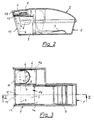
- FIG. 1 shows a trap according to the invention schematically in an axionometric view
- FIG. 2 shows a cross section through a trap according to the invention in elevation along the line II-II in FIG. 3
- FIG. 3 shows a view of the trap from above with the cover removed.
- the trap consists essentially of the housing 1, the cover 2, the input flap 3, which is connected to the support plate 4 via the axis 12, and the release member 7 consisting of the rocker 7a and the retaining tab 7b, by means of which the input flap is tilted 3 and the support plate 4 is triggered.
- the tilted position of the input flap 3 and the support plate 4 is shown in dashed lines in FIGS. 2 and 3.
- the housing 1 is subdivided into the cage 1a and the liquid tank 1b, which are separated from one another by the intermediate wall 9 except for a connection opening 8.
- the entrance opening 11 is provided near the high edge 15 in the side wall 10 of the housing.
- the cover 2 connected to the housing 1 via the hinge 13 is lifted off the housing 1, then liquid 6 is filled into the liquid tank 1b and a tablet 5 is placed on the support plate 4.
- the input flap 3 is fixed in the open position by means of the rocker 7a and the retaining tab 7b and the housing 1 is closed again by the cover 2.
- the retaining tab 7b of the release member 7 releases the input flap 3, which then falls into its closed position.
- the support plate 4 is tilted along with the inlet flap 3 via the axis 12, as a result of which the tablet 5 positioned on the support plate 4 falls into the liquid 6 of the liquid tank 1b.
- the chemical of the tablet 5 then reacts with the liquid 6 and releases the gas which is fatal to the small animal. This gas flows through the connection opening 8 from the liquid tank 1b into the cage 1a, where the animal is enclosed and is finally killed.
Landscapes
- Life Sciences & Earth Sciences (AREA)
- Health & Medical Sciences (AREA)
- Pest Control & Pesticides (AREA)
- Insects & Arthropods (AREA)
- Chemical & Material Sciences (AREA)
- General Health & Medical Sciences (AREA)
- Environmental Sciences (AREA)
- Zoology (AREA)
- Wood Science & Technology (AREA)
- Engineering & Computer Science (AREA)
- Pharmacology & Pharmacy (AREA)
- Physics & Mathematics (AREA)
- Veterinary Medicine (AREA)
- Animal Behavior & Ethology (AREA)
- Epidemiology (AREA)
- Optics & Photonics (AREA)
- Medicinal Chemistry (AREA)
- Public Health (AREA)
- Dispersion Chemistry (AREA)
- Toxicology (AREA)
- Catching Or Destruction (AREA)
- Feeding, Discharge, Calcimining, Fusing, And Gas-Generation Devices (AREA)
- Housing For Livestock And Birds (AREA)
- Medicines Containing Material From Animals Or Micro-Organisms (AREA)
Abstract
Description
- Die Erfindung betrifft eine Falle für Kleintiere, insbesondere Mäuse, mit einem nach oben offenen Gehäuse, das einen das Kleintier aufnehmenden Käfig aufweist, der eine durch eine schwenkbare Eingangsklappe verschließbaren Eingangsöffnung aufweist, mit einem zu öffnenden Deckel, der das Gehäuse abschließen kann, und mit einem Fangmechanismus zum Einbringen des Kleintiers in den Käfig, wobei eine Vergasungsvorrichtung im Gehäuse vorgesehen ist, die nach Verschluß der Eingangsöffnung den Käfig mit für das Kleintier tödlichem Gas füllt, und die eine vom Kleintier über ein Auslöseorgan betätigbare Einwurfeinrichtung aufweist, welche durch das Einwerfen einer Tablette aus einer in Reaktion mit einer Flüssigkeit gasbildenden Chemikalie in einen im Gehäuse vorgesehenen Flüssigkeitstank das tödliche Gas bildet.
- Eine Falle für Kleintiere der eingangs genannten Art ist aus der AT-PS 391 586 bekannt. Das Prinzip der Vorrichtung beruht auf folgender Arbeitsweise: Sobald das Kleintier in die Eingangsöffnung eintritt, löst es über eine Wippe die Eingangsklappe aus, sodaß das Kleintier im Gehäuse gefangen ist. Über einen weiteren Auslösemechanismus betätigt das Kleintier eine Einwurfeinrichtung, welche eine Tablette in eine Flüssigkeit befördert, wobei eine Reaktion stattfindet, die ein für das Kleintier tödliches Gas erzeugt.
- Derartige Fallen haben den Vorteil, daß auch ein köderloser Einsatz möglich ist, und daß bei einem gefangenen Tier ein schneller und schmerzfreier Tod eintritt. Die Tablette besteht dabei aus ungiftigen, gasbildenden Wirkstoffen, wodurch spielende Kinder in keiner Weise durch Schadstoffe gefährdet sind.
- Allerdings hat die in der AT-PS 391 586 beschriebene Falle den Nachteil eines hohen Herstellungaufwandes und damit verbunden, relativ hoher Herstellungskosten. Zudem kommt, daß die Handhabung und Reinigung der Falle nicht gerade einfach ist.
- Aufgabe der Erfindung ist es, diese Nachteile zu vermeiden und eine gegenüber dem Stand der Technik einfachere Falle zu konzipieren, wobei die genannten Vorteile weiterbestehen bleiben.
- Erfindungsgemäß ist daher vorgesehen, daß die Einwurfeinrichtung eine schwenkbare Tragplatte aufweist, auf welche die Tablette auflegbar ist, daß die Tragplatte in dem Flüssigkeitstank über der Flüssigkeit angeordnet ist, und daß die Tragplatte nach oder gemeinsam mit der Eingangsklappe kippbar ist, um das Einwerfen der Tablette in die Flüssigkeit zu bewirken, wobei die Schwenkbewegung der Tragplatte direkt oder indirekt an die Schwenkbewegung der Eingangsklappe gekoppelt ist. Durch die sehr einfach aufgebaute Einwurfeinrichtung und die Koppelung der Bewegung der Tragplatte mit der Eingangsklappe, ist ein sehr kompakter und einfacher Aufbau der Falle und damit eine kostengünstige Herstellung möglich. Das Kleintier kann durch Betätigen eines einzigen Auslöseorganes sowohl die Schwenkbewegung der Tragplatte, als auch die Schwenkbewegung der Eingangsklappe einleiten. Vorzugsweise ist dabei vorgesehen, daß die Schwenkachse der Tragplatte von der Schwenkachse der Eingangsklappe direkt oder indirekt angetrieben ist, wobei in weiterer Ausbildung, die Schwenkachsen der Tragplatte und der Eingangsplatte in Form einer einzigen gemeinsamen Achse ausgebildet sein können. Die Tragplatte und die Eingangsplatte können dabei aus einem Stück geformt sein.
- In einer bevorzugten Ausführungsvariante ist vorgesehen, daß die Falle höchstens aus den vier folgenden Teilen besteht, nämlich dem Käfig und den Flüssigkeitstank beinhaltenden Gehäuse, dem Deckel, einer aus der Eingangsklappe, der Tragplatte und der diese miteinander verbindenden Achse bestehenden Einheit, sowie dem vom Kleintier zu betätigenden Auslöseorgan zur Schließung der Eingangsklappe, wobei die Schlieβung ausschließlich durch das Eigengewicht der vorigen Einheit zusammen mit dem Gewicht der Tablette erfolgt. Durch die geringe Anzahl der Teile wird die Wartung und Reinigung sowie die Herstellung und der Zusammenbau der Falle sehr vereinfacht.
- Eine weitere Vereinfachung wird erreicht, wenn der Deckel und das Gehäuse einstückig ausgebildet sind, wobei beide durch ein Scharnier beweglich verbunden sind.
- Um eine rasche Wirkung des tödlichen Gases zu erreichen, sollte das Gehäuse durch den Deckel abdichtend verschließbar sein.
- In einer bevorzugten Ausführungsvariante ist vorgeshen, daß der Flüssigkeitstank und der Käfig mittels einer Zwischenwand des Gehäuses getrennt sind und daß eine im Deckel und/oder im Gehäuse angeordnete Verbindungsöffnung oder -leitung vorgesehen ist, und daß das Volumen des Flüssigkeitstanks kleiner ist als das Volumen des Käfigs, so daß das erzeugte Gas fast vollständig von dem Flüssigkeitstank in den Käfig fließen kann. Das Gehäuse der Falle schließt somit nur die beiden Räume, Käfig und Flüssigkeitstank ein. Eine komplizierte Unterteilung des Gehäuseinneren ist daher nicht erforderlich.
- Eine sichere Funktion der Falle ist gewährleistet, wenn die Tablette als gasbildenden Wirkstoff ein Salz der Kohlensäure, vorzugsweise Natriumhydrogencarbonat, enthält und die Flüssigkeit im wesentlichen aus Wasser besteht, das vorzugsweise einen Zusatz von Zitronensäure-1-hydrat enthält. Als tödliches Gas wird so Kohlendioxid erzeugt, das vollkommen ungiftig ist und auch sonst bei der Verwendung keinerlei Probleme verursacht. Der Effekt von Kohlendioxid besteht darin, daß dieses Gas den für die Atmung erforderlichen Sauerstoff verdrängt, wodurch der Tod durch Ersticken eintritt. Dieser Tod ist jedoch keineswegs qualvoll, sondern eher von euphorischen Zuständen begleitet, wie sie etwa vom Höhenrauch bekannt sind. Außerdem sind die erforderlichen Chemikalien, wie Natriumhydrogencarbonat, einfach zu handhaben, ungefährlich und billig. Im Prinzip ist die Füllung des Tanks mit Wasser ausreichend. Zur Beschleunigung der Gasbildungsreaktion ist jedoch die Zugabe eines sauren Mediums, wie etwa Zitronensäure-1-hydrat vorteilhaft.
- In einer sehr einfach herzustellenden Ausführungsvariante ist vorgesehen, daß das Gehäuse der Falle im wesentlichen so geformt ist, daß, in Eingangsrichtung, der Käfig und der Flüssigkeitstank nebeneinander angeordnet sind, wobei die Eingangsöffnung unmittelbar neben einer Hochkante des Gehäuses, vorzugsweise auf gleicher Front mit einer den Flüssigkeitstank zum Teil bildenden Seitenwand des Gehäuses, angeordnet ist, und daß die Falle vom Typ der köderlosen Fallen ist.
- Es ist eine Erfahrungstatsache, daß Mäuse und verwandte Kleintiere Räume nicht durchqueren, sondern soweit als möglich die Wände entlanglaufen. Aus diesem Grunde ist die Eingangsöffnung so angeordnet, daß sie bei richtig aufgestellter Falle unmittelbar neben der Wand des Raumes liegt. Die Maus wird also zwangsläufig und ohne von einem Köder gelockt worden zu sein, in die Falle hineinlaufen.
- In einer sehr wirkungsvollen Ausführungsvariante ist vorgesehen, daß das Auslöseorgan eine unmittelbar hinter der Eingangsöffnung angebrachte Wippe aufweist, die in ihrer Ruhestellung die Eingangsklappe, vorzugsweise über eine Haltelasche, in der geöffneten Position hält und die unter Belastung etwa durch ein Kleintier in eine andere Stellung kippt und die Eingangsklappe freigibt.
- Sämtliche Teile der Falle können aus Kunststoff hergestellt sein. Dies hat den Vorteil einer sehr einfachen und kostengünstigen Herstellung und ermöglicht eine pflegeleichte Handhabung der Falle. Dies trägt wesentlich zur Hygiene bei.
- Im folgenden wird die Erfindung anhand eines in den Figuren dargestellten Ausführungsbeispieles näher erläutert. Es zeigen Fig. 1 eine erfindungsgemäße Falle schematisch in axionometrischer Darstellung, Fig. 2 einen Querschnitt durch eine erfindungsgemäße Falle im Aufriß nach der Linie II-II in Fig. 3, Fig. 3 eine Ansicht auf die Falle von oben bei abgenommenem Deckel.
- Die Falle besteht im wesentlichen aus dem Gehäuse 1, dem Deckel 2, der Eingangsklappe 3, welche über die Achse 12 mit der Tragplatte 4 verbunden ist, sowie dem aus der Wippe 7a und der Haltelasche 7b bestehenden Auslösorgan 7, durch welches das Kippen der Eingangsklappe 3 und der Tragplatte 4 ausgelöst wird. Die gekippte Lage der Eingangsklappe 3 und der Tragplatte 4 ist in den Fig. 2 und 3 strichliert eingezeichnet. Das Gehäuse 1 ist unterteilt in den Käfig 1a und den Flüssigkeitstank 1b, welche durch die Zwischenwand 9 bis auf eine Verbindungsöffnung 8 voneinander getrennt sind. Die Eingangsöffnung 11 ist nahe der Hochkante 15 in der Seitenwand 10 des Gehäuses vorgesehen.
- Zur Vorbereitung der Falle wird der über das Scharnier 13 mit dem Gehäuse 1 verbundene Deckel 2 von dem Gehäuse 1 abgehoben, dann wird Flüssigkeit 6 in den Flüssigkeitstank 1b gefüllt und eine Tablette 5 auf die Tragplatte 4 gelegt. Die Eingangsklappe 3 wird mittels der Wippe 7a und der Haltelasche 7b in der offenen Stellung fixiert und das Gehäuse 1 durch den Deckel 2 wieder geschlossen.
- Ein Kleintier tritt durch die Eingangsöffnung 11 in den Käfig 1a ein. Bei einer Belastung des hinteren Abschnittes der Wippe 7a durch das Kleintier gibt die Haltelasche 7b des Auslöseorganes 7 die Eingangsklappe 3 frei, die dann in ihre geschlossene Position fällt. Gleichzeitig wird über die Achse 12 die Tragplatte 4 mit der Eingangsklappe 3 mitgekippt, wodurch die auf der Tragplatte 4 positionierte Tablette 5 in die Flüssigkeit 6 des Flüssigkeitstankes 1b fällt. Die Chemikalie der Tablette 5 reagiert dann mit der Flüssigkeit 6 und setzt das für das Kleintier tödliche Gas frei. Dieses Gas strömt über die Verbindungsöffnung 8 vom Flüssigkeitstank 1b in den Käfig 1a, wo das Tier eingeschlossen ist und schließlich getötet wird.
Claims (11)
- Falle für Kleintiere, insbesondere Mäuse, mit einem nach oben offenen Gehäuse (1), das einen das Kleintier aufnehmenden Käfig (1b) aufweist, der eine durch eine schwenkbare Eingangsklappe (3) verschließbaren Eingangsöffnung (11) aufweist, mit einem zu öffnenden Deckel (2), der das Gehäuse (1) abschließen kann, und mit einem Fangmechanismus zum Einbringen des Kleintiers in den Käfig (1b), wobei eine Vergasungsvorrichtung im Gehäuse (1) vorgesehen ist, die nach Verschluß der Eingangsöffnung (11) den Käfig (1b) mit für das Kleintier tödlichem Gas füllt, und die eine vom Kleintier über ein Auslöseorgan (7) betätigbare Einwurfeinrichtung aufweist, welche durch das Einwerfen einer Tablette (5) aus einer in Reaktion mit einer Flüssigkeit (6) gasbildenden Chemikalie in einen im Gehäuse (1) vorgesehenen Flüssigkeitstank (1b) das tödliche Gas bildet, dadurch gekennzeichnet , daß die Einwurfeinrichtung eine schwenkbare Tragplatte (4) aufweist, auf welche die Tablette (5) auflegbar ist, daß die Tragplatte (4) in dem Flüssigkeitstank (1b) über der Flüssigkeit (6) angeordnet ist, und daß die Tragplatte (4) nach oder gemeinsam mit der Eingangsklappe (3) kippbar ist, um das Einwerfen der Tablette (5) in die Flüssigkeit (6) zu bewirken, wobei die Schwenkbewegung der Tragplatte (4) direkt oder indirekt an die Schwenkbewegung der Eingangsklappe (3) gekoppelt ist.
- Falle nach Anspruch 1, dadurch gekennzeichnet, daß die Schwenkachse der Tragplatte (4) von der Schwenkachse der Eingangsklappe (3) direkt oder indirekt angetrieben ist.
- Falle nach Anspruch 2, dadurch gekennzeichnet, daß die Schwenkachsen der Tragplatte (4) und der Eingangsplatte (3) in Form einer einzigen gemeinsamen Achse (12) ausgebildet sind.
- Falle nach Anspruch 3, dadurch gekennzeichnet, daß die Falle höchstens aus den vier folgenden Teilen besteht, nämlich dem den Käfig (11) und den Flüssigkeitstank (1b) beinhaltenden Gehäuse (1), dem Deckel (2), einer aus der Eingangsklappe (3), der Tragplatte (4) und der diese miteinander verbindenden Achse (12) bestehenden Einheit (14), sowie dem vom Kleintier zu betätigenden Auslöseorgan (7) zur Schließung der Eingangsklappe (3), wobei die Schließung ausschließlich durch das Eigengewicht der vorigen Einheit (14) zusammen mit dem Gewicht der Tablette (5) erfolgt.
- Falle nach Anspruch 4, dadurch gekennzeichnet, daß der Deckel (2) und das Gehäuse (1) einstückig ausgebildet sind, wobei beide durch ein Scharnier (13) beweglich verbunden sind.
- Falle nach einem der Ansprüche 1 bis 5, dadurch gekenn zeichnet, daß das Gehäuse (1) durch den Deckel (2) abdichtend verschließbar ist.
- Falle nach Anspruch 5 oder 6, dadurch gekennzeichnet, daß der Flüssigkeitstank (1b) und der Käfig (1a) mittels einer Zwischenwand (9) des Gehäuses (1) getrennt sind und daß eine im Deckel (2) und/oder im Gehäuse (1) angeordnete Verbindungsöffnung oder -leitung (8) vorgesehen ist, und daß das Volumen des Flüssigkeitstanks (1b) kleiner ist als das Volumen des Käfigs (1a), so daß das erzeugte Gas fast vollständig von dem Flüssigkeitstank (1b) in den Käfig (1a) fließen kann.
- Falle nach einem der Ansprüche 1 bis 7, dadurch gekenn zeichnet, daß die Tablette (5) als gasbildenden Wirkstoff ein Salz der Kohlensäure, vorzugsweise Natriumhydrogencarbonat, enthält und daß die Flüssigkeit (6) im wesentlichen aus Wasser besteht, das vorzugsweise einen Zusatz von Zitronensäure-1-hydrat enthält.
- Falle nach einem der Ansprüche 1 bis 8, dadurch gekenn zeichnet, daß das Gehäuse (1) der Falle im wesentlichen so geformt ist, daß, in Eingangsrichtung, der Käfig (1a) und der Flüssigkeitstank (1b) nebeneinander angeordnet sind, wobei die Eingangsöffnung (11) unmittelbar neben einer Hochkante (15) des Gehäuses (1), vorzugsweise auf gleicher Front mit einer den Flüssigkeitstank (1b) zum Teil bildenden Seitenwand (10) des Gehäuses (1), angeordnet ist, und daß die Falle vom Typ der köderlosen Fallen ist.
- Falle nach Anspruch 5 oder 6, dadurch gekennzeichnet, daß das Auslöseorgan (7) eine unmittelbar hinter der Eingangsöffnung (11) angebrachte Wippe (7a) aufweist, die in ihrer Ruhestellung die Eingangsklappe (2), vorzugsweise über eine Haltelasche (7b), in der geöffneten Position hält und die unter Belastung etwa durch ein Kleintier in eine andere Stellung kippt und die Eingangsklappe (3) freigibt.
- Falle nach einem der Ansprüche 1 bis 10, dadurch gekenn zeichnet, daß sämtliche Teile der Falle aus Kunststoff hergestellt sind.
Applications Claiming Priority (2)
| Application Number | Priority Date | Filing Date | Title |
|---|---|---|---|
| AT1604/93 | 1993-08-11 | ||
| AT0160493A AT399081B (de) | 1993-08-11 | 1993-08-11 | Falle für kleintiere |
Publications (2)
| Publication Number | Publication Date |
|---|---|
| EP0638233A1 true EP0638233A1 (de) | 1995-02-15 |
| EP0638233B1 EP0638233B1 (de) | 1997-08-06 |
Family
ID=3517020
Family Applications (1)
| Application Number | Title | Priority Date | Filing Date |
|---|---|---|---|
| EP94890090A Expired - Lifetime EP0638233B1 (de) | 1993-08-11 | 1994-05-25 | Falle für Kleintiere |
Country Status (3)
| Country | Link |
|---|---|
| EP (1) | EP0638233B1 (de) |
| AT (2) | AT399081B (de) |
| DE (1) | DE59403621D1 (de) |
Cited By (9)
| Publication number | Priority date | Publication date | Assignee | Title |
|---|---|---|---|---|
| US20110078940A1 (en) * | 2009-09-24 | 2011-04-07 | Andrew Gauker | Single use hermetically sealing mousetrap with internal carbon dioxide killing mechanism |
| US20170202204A1 (en) * | 2016-01-20 | 2017-07-20 | Joseph Baxter | Animal Trap with Animal Entrance Encouraging Means |
| CN107114348A (zh) * | 2017-05-28 | 2017-09-01 | 无锡商业职业技术学院 | 一种捕鼠器 |
| CN107535476A (zh) * | 2017-10-19 | 2018-01-05 | 国网湖北省电力公司咸宁供电公司 | 一种变电站电缆沟连续捕鼠装置 |
| CN108173229A (zh) * | 2017-11-17 | 2018-06-15 | 江苏壹鼎崮机电科技有限公司 | 一种矿用防松防鼠管廊结构 |
| RU2658998C2 (ru) * | 2013-06-17 | 2018-06-26 | Томас ПЕКОРАРО | Ловушка для ловли животных, в частности мышиных |
| CN113519495A (zh) * | 2021-06-27 | 2021-10-22 | 刘修 | 一种新型的捕鼠装置 |
| FR3142652A1 (fr) * | 2022-12-05 | 2024-06-07 | Monsieur Madame Anti Nuisibles | Piège pour rongeurs |
| CN118680158A (zh) * | 2024-07-03 | 2024-09-24 | 陕西省动物研究所 | 一种鼠洞内水激活药剂的施放装置及其使用方法 |
Families Citing this family (2)
| Publication number | Priority date | Publication date | Assignee | Title |
|---|---|---|---|---|
| DE202014005061U1 (de) | 2014-06-17 | 2014-07-04 | Anke Schneider | Einrichtung zum Einfangen von Kleintieren (Lebendfalle) |
| DE202015000239U1 (de) | 2015-03-04 | 2015-03-10 | Anke Schneider | Einrichtung zum Einfangen von Kleintieren (Lebendfalle) |
Citations (3)
| Publication number | Priority date | Publication date | Assignee | Title |
|---|---|---|---|---|
| US4318241A (en) * | 1979-08-28 | 1982-03-09 | Fassauer Arthur L | Animal extermination trap |
| US4741121A (en) * | 1986-03-13 | 1988-05-03 | Andrew J. Pratscher | Gas chamber animal trap |
| AT391586B (de) * | 1988-08-12 | 1990-10-25 | Erstes Wiener Reinigungsinstit | Falle fuer kleintiere |
-
1993
- 1993-08-11 AT AT0160493A patent/AT399081B/de not_active IP Right Cessation
-
1994
- 1994-05-25 AT AT94890090T patent/ATE156329T1/de not_active IP Right Cessation
- 1994-05-25 DE DE59403621T patent/DE59403621D1/de not_active Expired - Fee Related
- 1994-05-25 EP EP94890090A patent/EP0638233B1/de not_active Expired - Lifetime
Patent Citations (3)
| Publication number | Priority date | Publication date | Assignee | Title |
|---|---|---|---|---|
| US4318241A (en) * | 1979-08-28 | 1982-03-09 | Fassauer Arthur L | Animal extermination trap |
| US4741121A (en) * | 1986-03-13 | 1988-05-03 | Andrew J. Pratscher | Gas chamber animal trap |
| AT391586B (de) * | 1988-08-12 | 1990-10-25 | Erstes Wiener Reinigungsinstit | Falle fuer kleintiere |
Cited By (14)
| Publication number | Priority date | Publication date | Assignee | Title |
|---|---|---|---|---|
| US8695274B2 (en) * | 2009-09-24 | 2014-04-15 | Woodstream Corporation | Single use hermetically sealing mousetrap with internal carbon dioxide killing mechanism |
| US20110078940A1 (en) * | 2009-09-24 | 2011-04-07 | Andrew Gauker | Single use hermetically sealing mousetrap with internal carbon dioxide killing mechanism |
| RU2658998C2 (ru) * | 2013-06-17 | 2018-06-26 | Томас ПЕКОРАРО | Ловушка для ловли животных, в частности мышиных |
| US10028500B2 (en) | 2013-06-17 | 2018-07-24 | Thomas Pecoraro | Trap for catching animals, in particular muridae |
| US20170202204A1 (en) * | 2016-01-20 | 2017-07-20 | Joseph Baxter | Animal Trap with Animal Entrance Encouraging Means |
| US10512258B2 (en) * | 2016-01-20 | 2019-12-24 | Joseph Baxter | Animal trap with animal entrance encouraging means |
| CN107114348A (zh) * | 2017-05-28 | 2017-09-01 | 无锡商业职业技术学院 | 一种捕鼠器 |
| CN107114348B (zh) * | 2017-05-28 | 2022-12-23 | 无锡商业职业技术学院 | 一种捕鼠器 |
| CN107535476A (zh) * | 2017-10-19 | 2018-01-05 | 国网湖北省电力公司咸宁供电公司 | 一种变电站电缆沟连续捕鼠装置 |
| CN108173229A (zh) * | 2017-11-17 | 2018-06-15 | 江苏壹鼎崮机电科技有限公司 | 一种矿用防松防鼠管廊结构 |
| CN108173229B (zh) * | 2017-11-17 | 2024-04-16 | 重庆市巫山城市建设(集团)有限公司 | 一种矿用防松防鼠管廊结构 |
| CN113519495A (zh) * | 2021-06-27 | 2021-10-22 | 刘修 | 一种新型的捕鼠装置 |
| FR3142652A1 (fr) * | 2022-12-05 | 2024-06-07 | Monsieur Madame Anti Nuisibles | Piège pour rongeurs |
| CN118680158A (zh) * | 2024-07-03 | 2024-09-24 | 陕西省动物研究所 | 一种鼠洞内水激活药剂的施放装置及其使用方法 |
Also Published As
| Publication number | Publication date |
|---|---|
| ATA160493A (de) | 1994-08-15 |
| AT399081B (de) | 1995-03-27 |
| EP0638233B1 (de) | 1997-08-06 |
| DE59403621D1 (de) | 1997-09-11 |
| ATE156329T1 (de) | 1997-08-15 |
Similar Documents
| Publication | Publication Date | Title |
|---|---|---|
| AT399081B (de) | Falle für kleintiere | |
| DE69104484T2 (de) | Elektromechanische geräte die tiere fortlaufend einfangen. | |
| DE2215797C3 (de) | Füllvorrichtung für aufblasbare Seenotrettungseinrichtungen | |
| DE3213530A1 (de) | Automatische rattenfalle | |
| DE102009019727B4 (de) | Falle zum Bekämpfen von Schadnagern | |
| DE2753922A1 (de) | Vorrichtung zum jederzeitigen herstellen eines mischgetraenkes aus sirup und wasser | |
| AT391586B (de) | Falle fuer kleintiere | |
| DE202019103475U1 (de) | Tierfalle | |
| DE1188860B (de) | Futterstofffreie Koeder zur Bekaempfung von Nagetieren | |
| CH338382A (de) | Waffe zur Nahbekämpfung eines Angreifers | |
| DE102004053106B3 (de) | Falle zum Fangen von Mäusen und ähnlichen Kleintieren | |
| DE2458995C2 (de) | Vorrichtung zum fangen von tieren | |
| DE100858C (de) | ||
| DE20301170U1 (de) | Tierfalle, Lebendfalle | |
| DE2310382A1 (de) | Futterautomat fuer zierfische | |
| EP0548525A1 (de) | Lebendfangkastenfalle | |
| DE164974C (de) | ||
| EP1044704A1 (de) | Feuerlöscher | |
| DE1953097A1 (de) | Beleuchtungseinrichtung fuer Bildwerfer mit Lampenausheber | |
| DE18049C (de) | Kieseiguhr-Desinfektor | |
| DE113805C (de) | ||
| DE803861C (de) | Automatisches Sperlingsfanggeraet | |
| DE826987C (de) | Vorrichtung zur Bekaempfung von Motten u. dgl. | |
| DE176785C (de) | ||
| EP0059822A1 (de) | Abfallbehälter |
Legal Events
| Date | Code | Title | Description |
|---|---|---|---|
| PUAI | Public reference made under article 153(3) epc to a published international application that has entered the european phase |
Free format text: ORIGINAL CODE: 0009012 |
|
| AK | Designated contracting states |
Kind code of ref document: A1 Designated state(s): AT BE CH DE ES FR GB IT LI LU NL SE |
|
| RAX | Requested extension states of the european patent have changed |
Free format text: SI PAYMENT 940530 |
|
| 17P | Request for examination filed |
Effective date: 19950116 |
|
| GRAG | Despatch of communication of intention to grant |
Free format text: ORIGINAL CODE: EPIDOS AGRA |
|
| GRAH | Despatch of communication of intention to grant a patent |
Free format text: ORIGINAL CODE: EPIDOS IGRA |
|
| 17Q | First examination report despatched |
Effective date: 19961018 |
|
| GRAH | Despatch of communication of intention to grant a patent |
Free format text: ORIGINAL CODE: EPIDOS IGRA |
|
| GRAA | (expected) grant |
Free format text: ORIGINAL CODE: 0009210 |
|
| AK | Designated contracting states |
Kind code of ref document: B1 Designated state(s): AT BE CH DE ES FR GB IT LI LU NL SE |
|
| AX | Request for extension of the european patent |
Free format text: SI PAYMENT 940530 |
|
| PG25 | Lapsed in a contracting state [announced via postgrant information from national office to epo] |
Ref country code: NL Free format text: LAPSE BECAUSE OF FAILURE TO SUBMIT A TRANSLATION OF THE DESCRIPTION OR TO PAY THE FEE WITHIN THE PRESCRIBED TIME-LIMIT Effective date: 19970806 Ref country code: IT Free format text: LAPSE BECAUSE OF FAILURE TO SUBMIT A TRANSLATION OF THE DESCRIPTION OR TO PAY THE FEE WITHIN THE PRESCRIBED TIME-LIMIT;WARNING: LAPSES OF ITALIAN PATENTS WITH EFFECTIVE DATE BEFORE 2007 MAY HAVE OCCURRED AT ANY TIME BEFORE 2007. THE CORRECT EFFECTIVE DATE MAY BE DIFFERENT FROM THE ONE RECORDED. Effective date: 19970806 Ref country code: GB Free format text: LAPSE BECAUSE OF FAILURE TO SUBMIT A TRANSLATION OF THE DESCRIPTION OR TO PAY THE FEE WITHIN THE PRESCRIBED TIME-LIMIT Effective date: 19970806 Ref country code: FR Free format text: LAPSE BECAUSE OF FAILURE TO SUBMIT A TRANSLATION OF THE DESCRIPTION OR TO PAY THE FEE WITHIN THE PRESCRIBED TIME-LIMIT Effective date: 19970806 Ref country code: ES Free format text: THE PATENT HAS BEEN ANNULLED BY A DECISION OF A NATIONAL AUTHORITY Effective date: 19970806 |
|
| REF | Corresponds to: |
Ref document number: 156329 Country of ref document: AT Date of ref document: 19970815 Kind code of ref document: T |
|
| REG | Reference to a national code |
Ref country code: CH Ref legal event code: EP |
|
| REF | Corresponds to: |
Ref document number: 59403621 Country of ref document: DE Date of ref document: 19970911 |
|
| PG25 | Lapsed in a contracting state [announced via postgrant information from national office to epo] |
Ref country code: SE Effective date: 19971106 |
|
| EN | Fr: translation not filed | ||
| NLV1 | Nl: lapsed or annulled due to failure to fulfill the requirements of art. 29p and 29m of the patents act | ||
| GBV | Gb: ep patent (uk) treated as always having been void in accordance with gb section 77(7)/1977 [no translation filed] |
Effective date: 19970806 |
|
| PG25 | Lapsed in a contracting state [announced via postgrant information from national office to epo] |
Ref country code: LU Free format text: LAPSE BECAUSE OF NON-PAYMENT OF DUE FEES Effective date: 19980525 |
|
| PG25 | Lapsed in a contracting state [announced via postgrant information from national office to epo] |
Ref country code: LI Free format text: LAPSE BECAUSE OF NON-PAYMENT OF DUE FEES Effective date: 19980531 Ref country code: CH Free format text: LAPSE BECAUSE OF NON-PAYMENT OF DUE FEES Effective date: 19980531 Ref country code: BE Free format text: LAPSE BECAUSE OF NON-PAYMENT OF DUE FEES Effective date: 19980531 |
|
| PLBE | No opposition filed within time limit |
Free format text: ORIGINAL CODE: 0009261 |
|
| STAA | Information on the status of an ep patent application or granted ep patent |
Free format text: STATUS: NO OPPOSITION FILED WITHIN TIME LIMIT |
|
| 26N | No opposition filed | ||
| BERE | Be: lapsed |
Owner name: PROCHAZKA WERNER Effective date: 19980531 |
|
| REG | Reference to a national code |
Ref country code: CH Ref legal event code: PL |
|
| PGFP | Annual fee paid to national office [announced via postgrant information from national office to epo] |
Ref country code: AT Payment date: 20000529 Year of fee payment: 7 |
|
| PGFP | Annual fee paid to national office [announced via postgrant information from national office to epo] |
Ref country code: DE Payment date: 20000629 Year of fee payment: 7 |
|
| PG25 | Lapsed in a contracting state [announced via postgrant information from national office to epo] |
Ref country code: AT Free format text: LAPSE BECAUSE OF NON-PAYMENT OF DUE FEES Effective date: 20010525 |
|
| PG25 | Lapsed in a contracting state [announced via postgrant information from national office to epo] |
Ref country code: DE Free format text: LAPSE BECAUSE OF NON-PAYMENT OF DUE FEES Effective date: 20020301 |