EP0638371B1 - Grossbehälterinnenraumwartungsverfahren und Wartungsgerät - Google Patents
Grossbehälterinnenraumwartungsverfahren und Wartungsgerät Download PDFInfo
- Publication number
- EP0638371B1 EP0638371B1 EP94305912A EP94305912A EP0638371B1 EP 0638371 B1 EP0638371 B1 EP 0638371B1 EP 94305912 A EP94305912 A EP 94305912A EP 94305912 A EP94305912 A EP 94305912A EP 0638371 B1 EP0638371 B1 EP 0638371B1
- Authority
- EP
- European Patent Office
- Prior art keywords
- chine
- arms
- container
- arm
- service apparatus
- Prior art date
- Legal status (The legal status is an assumption and is not a legal conclusion. Google has not performed a legal analysis and makes no representation as to the accuracy of the status listed.)
- Expired - Lifetime
Links
- 238000000034 method Methods 0.000 title claims abstract description 15
- 230000000087 stabilizing effect Effects 0.000 claims description 18
- 230000003028 elevating effect Effects 0.000 claims description 8
- 239000000725 suspension Substances 0.000 claims description 7
- 239000012530 fluid Substances 0.000 claims description 4
- 230000000750 progressive effect Effects 0.000 claims description 4
- 230000008602 contraction Effects 0.000 claims description 3
- 230000005540 biological transmission Effects 0.000 claims description 2
- 230000000694 effects Effects 0.000 claims description 2
- 238000004140 cleaning Methods 0.000 description 9
- 235000004443 Ricinus communis Nutrition 0.000 description 8
- 238000006073 displacement reaction Methods 0.000 description 8
- 239000007921 spray Substances 0.000 description 5
- 238000003466 welding Methods 0.000 description 5
- 238000000151 deposition Methods 0.000 description 4
- 238000009713 electroplating Methods 0.000 description 4
- 235000013361 beverage Nutrition 0.000 description 3
- 238000007689 inspection Methods 0.000 description 3
- 239000000463 material Substances 0.000 description 3
- 229920001084 poly(chloroprene) Polymers 0.000 description 3
- 238000005070 sampling Methods 0.000 description 3
- 241000282326 Felis catus Species 0.000 description 2
- 238000006243 chemical reaction Methods 0.000 description 2
- 238000012423 maintenance Methods 0.000 description 2
- 239000002253 acid Substances 0.000 description 1
- 238000004873 anchoring Methods 0.000 description 1
- 230000015572 biosynthetic process Effects 0.000 description 1
- 230000006835 compression Effects 0.000 description 1
- 238000007906 compression Methods 0.000 description 1
- 238000010276 construction Methods 0.000 description 1
- 238000005516 engineering process Methods 0.000 description 1
- 239000011521 glass Substances 0.000 description 1
- 238000003825 pressing Methods 0.000 description 1
- 239000011347 resin Substances 0.000 description 1
- 229920005989 resin Polymers 0.000 description 1
- 229910001220 stainless steel Inorganic materials 0.000 description 1
- 239000010935 stainless steel Substances 0.000 description 1
- 229920002994 synthetic fiber Polymers 0.000 description 1
- 230000001052 transient effect Effects 0.000 description 1
- 238000009423 ventilation Methods 0.000 description 1
- 230000000007 visual effect Effects 0.000 description 1
Images

Classifications
-
- E—FIXED CONSTRUCTIONS
- E04—BUILDING
- E04G—SCAFFOLDING; FORMS; SHUTTERING; BUILDING IMPLEMENTS OR AIDS, OR THEIR USE; HANDLING BUILDING MATERIALS ON THE SITE; REPAIRING, BREAKING-UP OR OTHER WORK ON EXISTING BUILDINGS
- E04G3/00—Scaffolds essentially supported by building constructions, e.g. adjustable in height
- E04G3/28—Mobile scaffolds; Scaffolds with mobile platforms
- E04G3/30—Mobile scaffolds; Scaffolds with mobile platforms suspended by flexible supporting elements, e.g. cables
-
- B—PERFORMING OPERATIONS; TRANSPORTING
- B08—CLEANING
- B08B—CLEANING IN GENERAL; PREVENTION OF FOULING IN GENERAL
- B08B9/00—Cleaning hollow articles by methods or apparatus specially adapted thereto
- B08B9/08—Cleaning containers, e.g. tanks
-
- B—PERFORMING OPERATIONS; TRANSPORTING
- B08—CLEANING
- B08B—CLEANING IN GENERAL; PREVENTION OF FOULING IN GENERAL
- B08B9/00—Cleaning hollow articles by methods or apparatus specially adapted thereto
- B08B9/08—Cleaning containers, e.g. tanks
- B08B9/087—Cleaning containers, e.g. tanks by methods involving the use of tools, e.g. brushes, scrapers
-
- B—PERFORMING OPERATIONS; TRANSPORTING
- B08—CLEANING
- B08B—CLEANING IN GENERAL; PREVENTION OF FOULING IN GENERAL
- B08B9/00—Cleaning hollow articles by methods or apparatus specially adapted thereto
- B08B9/08—Cleaning containers, e.g. tanks
- B08B9/093—Cleaning containers, e.g. tanks by the force of jets or sprays
-
- B—PERFORMING OPERATIONS; TRANSPORTING
- B63—SHIPS OR OTHER WATERBORNE VESSELS; RELATED EQUIPMENT
- B63B—SHIPS OR OTHER WATERBORNE VESSELS; EQUIPMENT FOR SHIPPING
- B63B57/00—Tank or cargo hold cleaning specially adapted for vessels
-
- E—FIXED CONSTRUCTIONS
- E04—BUILDING
- E04G—SCAFFOLDING; FORMS; SHUTTERING; BUILDING IMPLEMENTS OR AIDS, OR THEIR USE; HANDLING BUILDING MATERIALS ON THE SITE; REPAIRING, BREAKING-UP OR OTHER WORK ON EXISTING BUILDINGS
- E04G3/00—Scaffolds essentially supported by building constructions, e.g. adjustable in height
- E04G3/24—Scaffolds essentially supported by building constructions, e.g. adjustable in height specially adapted for particular parts of buildings or for buildings of particular shape, e.g. chimney stacks or pylons
- E04G3/246—Scaffolds essentially supported by building constructions, e.g. adjustable in height specially adapted for particular parts of buildings or for buildings of particular shape, e.g. chimney stacks or pylons following the inside contour of a building
-
- G—PHYSICS
- G21—NUCLEAR PHYSICS; NUCLEAR ENGINEERING
- G21C—NUCLEAR REACTORS
- G21C17/00—Monitoring; Testing ; Maintaining
- G21C17/003—Remote inspection of vessels, e.g. pressure vessels
- G21C17/01—Inspection of the inner surfaces of vessels
-
- Y—GENERAL TAGGING OF NEW TECHNOLOGICAL DEVELOPMENTS; GENERAL TAGGING OF CROSS-SECTIONAL TECHNOLOGIES SPANNING OVER SEVERAL SECTIONS OF THE IPC; TECHNICAL SUBJECTS COVERED BY FORMER USPC CROSS-REFERENCE ART COLLECTIONS [XRACs] AND DIGESTS
- Y02—TECHNOLOGIES OR APPLICATIONS FOR MITIGATION OR ADAPTATION AGAINST CLIMATE CHANGE
- Y02E—REDUCTION OF GREENHOUSE GAS [GHG] EMISSIONS, RELATED TO ENERGY GENERATION, TRANSMISSION OR DISTRIBUTION
- Y02E30/00—Energy generation of nuclear origin
- Y02E30/30—Nuclear fission reactors
Definitions
- THIS INVENTION relates to servicing of large containers. It relates more specifically to a method of servicing an interior of a large container, and to a servicing apparatus suitable for use inside a large container.
- this invention will advantageously be applicable in inspection, maintenance and other services, like cleaning, in respect of large vessels or containers in the food and beverage industry, the petrochemical industry, or the like.
- the invention is, however, not limited to those fields.
- French Patent Document 2 289 249 discloses cleaning of a large, round, cylindrical container tank having a narrow access opening in a top thereof by lowering a collapsible support by means of a winch mounted at a high elevation on a gantry crane via the narrow opening into the tank.
- the collapsible support is supported via a rigid post extending from an external support base mounted on the gantry crane through the opening.
- the collapsible support has radial arms pivoted at inner ends thereof to a bottom of the rigid post, to allow the radial arms to be pivoted between closed conditions alongside the post to open conditions extending radially decumbently from the post.
- Stays are pivoted at inner ends thereof to a bush around the post and at outer ends thereof to the radial arms at positions spaced toward outer ends of the radial arms.
- the bush is displaceable up and down the post by means of lead screws driven from an electric motor mounted on the gantry crane. Appropriate displacement of the bush selectively opens and closes the radial arms.
- the radial arms carry rams which can be extended to abut an inner wall surface of the tank to anchor the collapsible support.
- the collapsible support can be pivoted by withdrawing the rams and turning the post by means of torque providing means mounted on the external base on the gantry crane.
- US patent document 5 179 757 discloses a collapsible support which is similar to the disclosure in French patent document 2 289 249 in many respects and differs therefrom in that the collapsible support is suspended by means of a flexible cable extending into the tank, in that the radial arms are openable and closable by displacement of the bush by means of a hydraulic piston and cylinder arrangement; in that the collapsible support supports a working tool such as to form a stable base for the working tool from which it can be rotated relative to the stable base and tilted relative to the stable base.
- a method of servicing an internal wall of a large, stationary, round cylindrical container which has a narrow access opening only in a top thereof, by means of a service apparatus including
- the length of the chine may be at least about one half the nominal diameter of the container.
- the method may be effected by performing a service operation manually by means of at least one operator supported within the container on the apparatus.
- performing the service operation may be mechanically by means of a mechanical device.
- performing the service operation may include one of:
- the method may include controlling the mechanical device from a remote position.
- the method may further include mechanically moving the apparatus within the container, moving including at least one of raising, lowering and pivoting the apparatus.
- the method may then include controlling operation of the mechanical device and moving of the apparatus by means of programmable logic.
- the method may include recording transient positions of said mechanical device relative to the inner wall surface against time. This feature will enable a service operation to be performed automatically, under programmed logic control, at predetermined positions of the internal wall surface.
- a service apparatus suitable for use in servicing an internal wall of a large, stationary, round cylindrical container which has a narrow access opening only in a top thereof, the service apparatus including
- Driving connection between the deploying means and the rotary drive means for deploying may be via a collar forming part of the deploying means, the collar being displaceable to and fro along the chine by means of the rotary drive means for deploying, one of the ends of the respective stays being pivoted to the arms at positions spaced from the radially inner ends of the respective arms and opposed ends of the respective stays being pivoted to the collar.
- Driving connection between the deploying means and the rotary drive means for deploying may be via a lead screw anchored on one of the chine and the collar, and via a complemental screw thread receiving the lead screw and being located on the other of the chine and the collar, the rotary drive means for deploying being arranged to effect relative rotation between the lead screw and the screw thread.
- the drive means for rotating may include a drive wheel arranged at the radially outer end of one radial arm drivingly to abut the inner wall in use, a rotary drive motor and by transmission means drivingly connecting the drive wheel to the rotary drive motor.
- the drive wheel may be separate from the roller of said one radial arm, the drive wheel being mounted by means of drive wheel mounting means which is selectively adjustable between a withdrawn condition in which the drive wheel is withdrawn from contact with the internal wall and an extended condition in which the drive wheel is urged into driving contact with the internal wall.
- the drive wheel mounting means may include a cradle on which the drive wheel is rotatably supported, generally radially extending slide means on which the cradle is slidable, and a pressurized fluid operable plunger and cylinder arrangement arranged selectively to slide the cradle to and fro along the slide means between said withdrawn condition and said extended condition of the drive wheel.
- the service apparatus may include stabilizing members mounted on at least two radial arms such as to be displaceable between withdrawn conditions in which the stabilizing members are withdrawn from the internal wall and extended conditions in which the stabilizing members abut the internal wall; and interlocking means operative between the stabilizing members and the winch to prevent the winch from being operated if the stabilizing members are in their extended conditions.
- Said elevating means may be suitable for elevating personnel, in that one radial arm may include a walkway and a collapsible railing adjacent the walkway to allow an operator to approach the internal wall manually to perform a servicing operation on the internal wall.
- the service apparatus may include a mechanical service device and mounting means for mounting the mechanical service device toward an extremity of one of the arms.
- the mechanical service device may be one of
- the service apparatus may include displacement means for selectively displacing the apparatus in respect of at least one of pivoting, raising and lowering the apparatus within the container. Pivoting may be effected by the driven roller, and raising and lowering may be effected by the winch means.
- the service apparatus may then include remote control means for controlling the displacement means and the mechanical service device from a position externally of the container.
- the remote control means may include programmable logic control means.
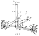
- a service apparatus in simple format in accordance with the invention is generally indicated by reference numeral 10.
- the service apparatus 10 is intended for use with relatively large containers, especially in the food and beverage industry, such as the container or vessel indicated by reference numeral 12.
- the container 12 is of generally cylindrical form having a domed upper end and a narrow upper opening 14 through which entry into the interior of the container 12 is to be obtained.
- the container 12 has a cylindrical side wall 16 having an internal surface 18.
- the invention relates to servicing said internal surface 18, such as by way of inspection, maintenance, cleaning and the like.
- the surface 18 will generally be of stainless steel, but may be of glass, in the form of a resin liner, or similar fragile material.
- the container 12 can be high, of the order of up to 20 m or more. It may have a nominal diameter of typically about 3m or more. Thus, the container 12 is large. Furthermore, the opening 14 is narrow, typically of the order of 400mm diameter.
- the service apparatus 10 in accordance with the invention is collapsible as shown in Figure 1 to allow it to be lowered through the narrow opening 14 in its collapsed condition.
- the service apparatus 10 can be extended or deployed generally as indicated in Figures 2 and 3. In its deployed condition, it can support one or more operators who can then use the apparatus, inter alia, in the manner of a platform to allow access to the surface 18 of the side wall 16.
- the service apparatus 10 includes a central body or chine 24 in the form of a hollow shaft.
- a polygonal base 26 which, in this embodiment, is triangular.
- an arm 28 which, by virtue of the hinge 30, is movable between a collapsed condition as shown in Figure 1 in which each arm extends longitudinally or axially, decumbently with the shaft 24, and a deployed condition as shown in Figures 2 and 3 in which the arms 28 are folded open to extend outwardly, generally radially, from the base 26 generally at right angles to the shaft 24.
- the chine or shaft 24 has a length equal to at least half the nominal diameter of the container 12.
- the arms 28 are conveniently pivotal by means of a deploying assembly comprising a collar 32 slidable along the shaft 24 as indicated by reference numeral 36, and three stays 34, respectively pivotally attached between the collar 32 and the respective arms 28.
- a deploying assembly comprising a collar 32 slidable along the shaft 24 as indicated by reference numeral 36, and three stays 34, respectively pivotally attached between the collar 32 and the respective arms 28.
- the arms 28 can be supported in their deployed conditions by means of support cables (not shown).
- a cable can extend from an outer end of each arm to an upper location on the shaft, so that when the arms are in their deployed conditions the support cables are in tension.
- a manually operable winch 38 is provided at an upper end of the shaft 28 and having a rope 40 attached to the collar 32.
- the winch 38 and the rope 40 By means of the winch 38 and the rope 40, the collar 32 can be hoisted upwardly to fold the arms 28 into their collapsed condition.
- An arrangement, which is preferred to this arrangement, however, is described hereinbelow.
- each arm 28 there is provided a castor assembly 44 comprising a castor wheel 46 mounted at an end of an arm 48.
- the castor assembly 44 is advantageously resiliently biassed outwardly by means of a spring received within the arm 28 and not shown in the drawings.
- the resilient bias will ensure that the castor wheels 46 run against the inner surface 18.
- Dimensional inaccuracies and tolerances in the apparatus 10 and also in the container 12 are accommodated by the resilient biassing.
- At least one arm 28 carries a cat walk 42 in the form of a grid to allow an operator to walk along the arm 28 from the body 24 toward the side wall 16.
- the apparatus 10 is suspended by means of a cable 20 from a mechanical hoist 22 anchored externally of the container 12.
- the apparatus 10 can be raised and lowered into and out of the container 12, and also within the container 12 by means of the hoist 22.
- stabilizing means 50 is provided for each arm 28.
- Each stabilizing means 50 comprises a lever 52 pivoted or hinged as indicated by reference numeral 54 at one end of the lever 52 at an outer end of its arm 28.
- a pneumatic plunger and cylinder arrangement 56 is operatively arranged between the lever 52 and the arm 28 to displace the lever 52 between a collapsed condition in which it extends generally decumbently with its arm 28, and an extended condition in which it extends upwardly from the end of the arm 28, generally at right angles.
- a grip pad 60 At a free end of the lever 52, and extending outwardly, there is provided a grip pad 60 by means of which the inner surface 18 of the side wall 16 is abutted in use.
- the stabilizing means 50 when operative, stabilizes the device against the container.
- a nozzle assembly 62 toward an outer end of one arm 28.
- the nozzle assembly 62 is supplied by means of a supply line 64.
- the nozzle assembly 62 can be arranged in oblique fashion such that a fluid can be sprayed obliquely tangentially against the surface 18.
- a motor generally indicated by reference numeral 66 may be provided at the end of at least one arm.
- a drive wheel is drivingly connected to the motor 66 to ride along the surface 18 to propel the apparatus 10 in an appropriate direction.
- Cables may connect one arm to another to maintain their angular spacing.
- the arms are supported in their positions relative to each other by means of said cables.
- a control panel 70 is provided against the shaft 24 to be accessible to an operator standing on the cat walk 42 and by means of which the various functions of the apparatus 10 can be controlled.
- a platform which can be inserted into a container of the kind described through its narrow opening and can be deployed within the container to provide a work platform for personnel.
- the apparatus 10 acts as a carrier for mechanical service apparatus which can be used within the container 12, if desired from remote positions.
- the service apparatus is generally indicated by reference numeral 110.
- the service apparatus 110 is more sophisticated and has more accessories or auxiliary service components than the collapsible service apparatus 10 of Figures 1 to 3.
- the service apparatus 110 is similar to the service apparatus 10 and like reference numerals refer to like components.
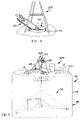
- the collapsible service apparatus 110 is shown in its collapsed condition and is being introduced into a vessel 112 via a narrow top opening 114 thereof.
- the service apparatus 110 is man-handled by an operator through the opening 114.
- the apparatus 110 is supported from a winch mounted at an upper end of a gantry 202 as will be described in more detail with reference to Figure 5.
- the winch may be hydraulically or electrically (low voltage direct current) driven. It is important to appreciate that the apparatus 110, in its collapsed condition, is narrow - at least sufficiently narrow to pass through a 400 mm diameter opening.
- the apparatus 110 is of relatively light weight, advantageously less than about 100 kg. It is conveniently contained within a bag of flexible material.
- the gantry 202 is shown being free-standing over the opening 114. It mounts a winch 122 mounted about a transverse axis and which is electrically operable, conveniently by means of a low voltage direct current electric motor e.g. between about 12 and about 36 volts, say 24 volts.
- a winch 122 mounted about a transverse axis and which is electrically operable, conveniently by means of a low voltage direct current electric motor e.g. between about 12 and about 36 volts, say 24 volts.
- the winch can be operated from readily available lead acid batteries. Instead, it may be hydraulically driven by means of a hydraulic motor.
- a pair of winches may be used in parallel being attached to the apparatus 110 by means of separate cables and being operable by means of separate drive motors.
- the winches be operable from a common control panel.
- Reference numeral 204 indicates generally accessories or auxiliary components which can be used with the collapsible service apparatus 110. Those accessories or auxiliary components will depend on the intended use of the apparatus but may include components like ventilating means for providing ventilation within the vessel 112, a cleaning solution for cleaning interior surfaces of the vessel 112, gas welding apparatus, containers for samples, lighting means, and the like.
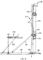
- the apparatus 110 is shown in its deployed condition within the container 112, depending via a cable 120 from the winch 122.
- displacement of the collar 132 up and down the hollow post or chine 124 respectively to collapse and to deploy the arms 128, is effected by means of a lead screw 140 which is mounted for rotation along the post 124.
- the lead screw 140 is threadingly engaged with a threaded bush 206 located on the collar 132 and is driven by means of a motor 138.
- the motor is conveniently a low voltage direct current motor, e.g. a 24 volt DC motor.
- the collapsible service apparatus includes a ladder 212 in the form of a central chine 214 and a plurality of transversely extending foot rests 216.
- the chine 214 is mounted on the central post 124.
- the ladder 212 is intended for use when the collapsible service apparatus 110 is spaced relatively closely underneath the opening 114 of the vessel 112, and in its deployed condition, to allow personnel to climb down from the dcmed top of the vessel 112 to the service platform and vice versa.
- the service apparatus has three arms 128, only one of which is intended for use by personnel. That arm 128 has a safety rail formed by linkages generally indicated by reference 208 arranged, in co-operation with the central post 124 and the arm 128, in the nature of a parallelogram thus to be collapsed when the arms 128 are collapsed, and deployed when the arms are deployed.
- a U-shaped, outwardly slidably extension 210 is provided on the rails to allow personnel to walk to the end of the arm 128 still within the confines of the rails.
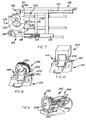
- FIG. 7 an end portion of one arm 128 is shown.
- the specific arm shown is used to drive the apparatus in a rotary direction about the post 124.
- the arm 128 of Figure 7 carries guide means 144 and stabilizing means 150 which will be described hereinafter and which are provided on each of the other two arms as well.
- the guide means 144 includes a castor wheel 146 at an end of a shaft 148 which is resiliently received via a spring 218 arranged to operate in compression within a sleeve 219.
- the spring 218 biasses the castor wheel 146 outwardly such that, in use, it will run against an inner surface 118 of the vessel 112.
- the castor wheel 146 has a tread, conveniently of light grey Neoprene, and selected not to leave traces on the inner surface 118.
- the stabilizing means 150 includes a ram 152 which is reciprocal by means of a pneumatic plunger and cylinder arrangement 156.
- the ram 152 carries a foot 160 of soft synthetic material e.g. light grey Neoprene.
- the pneumatic plunger and cylinder arrangement 156 of each arm is extended to urge the respective foot 160 against the inner surface 118.
- the pneumatic plunger and cylinder arrangement 156 is contracted to retract the ram 152 and foot 160.
- an interlock system between the stabilizing means 150 and the winch 122 such that they cannot be operated simultaneously i.e. such that the winch can be utilized only when the pneumatic plunger and cylinder arrangements are in their contracted conditions.
- the specific arm 128, as mentioned above, carries drive means generally indicated by reference numeral 220.
- the drive means includes a drive wheel 222 rotatable about an upwardly directed axis such as, in use, to drive the collapsible service apparatus 110 in a rotary direction.
- the wheel 222 has a tread, e.g. of light grey Neoprene, selected not to leave traces on the inner surface 118.
- the wheel 222 is mounted for rotation about its axis on a cradle 224, more specifically via a swing arm 226.
- the wheel 222 can be driven via a capstan 228 drivingly connected to a low voltage direct current motor, more specifically a 24 volt DC motor mounted underneath the arm 128 and which is not visible in the drawing. Instead, it may be driven by means of a hydraulic or pneumatic motor.
- the cradle 224 is guided by means of generally radially extending, circumferentially spaced guide means 232 and displacement and subsequent anchoring in a desired radial position are effected via an anchor and displacement push rod 230.
- the push rod 230 may be extensible and contractible pneumatically.
- the apparatus 110 has rotary cleaning means generally indicated by reference numeral 250 and in the form of a rotary brush mounted for rotation about a radially extending axis at an end of one arm 128 via a bracket 252. It is rotatable by means of a motor 254 drivingly connected to the rotary brush via an angled drive.
- the arm 128 mounting the cleaning brush 250 is the third arm 128 i.e. neither the arm intended for use by personnel, nor the arm carrying the drive means 144.
- the arm carrying the rotary brush 250 also has the guide means 144 and the stabilizing means 150.
- the bracket 252 can readily be mounted on and dismantled from the end of the platform 128.
- the rotary cleaning brush 250 can be utilized in combination with a spray nozzle 259 which can be directed generally radially outwardly and arranged to direct fluid on the inner surface 118 adjacent the rotary brush 250.
- a spray nozzle 259 which can be directed generally radially outwardly and arranged to direct fluid on the inner surface 118 adjacent the rotary brush 250.
- Such nozzle may be adapted to provide a pulsating flow.
- swabbing means generally indicated by reference numeral 240 may selectively be mounted at an end of the arm 128 of Figure 8 in place of the rotary brush.
- the swabbing means 240 can, likewise, readily be mounted on and dismantled from the end of that arm 128.
- the swabbing means 240 includes an indexing head 242 having, in this embodiment, twelve positions. At each position, there is provided a sampling head 248 at an end of a generally radially extending shaft 246 which can, selectively, be used as a ram to engage the inner surface 118 with its swabbing head and which can selectively also be rotated.
- Drive means for the various shafts 246 is indicated by reference numeral 244 and may be pneumatic drive means.
- Rotation of the indexing head 242 is controllable via the central control means.
- Each swab head 248 may conveniently have releasable attachment means such as Velcro strips attached thereto selectively to attach sample adhering means such as a swab to take a sample of the inner surface 118 at a preselected position.
- a camera and focusing means for the camera may be mounted.
- a camera may be a video camera, schematically indicated by reference numeral 263.
- a welding device such as a welding device, an electroplating device, a plasma spray depositing and electropolishing device, may be provided and may be mountable and dismantleable as shown in respect of the video camera 263 in Figure 10.
- the service apparatus 110 has the advantages of the apparatus 10. Those advantages are, for reasons of economy, not repeated. The service apparatus 110, however, has a number of additional advantages, some of which are mentioned below.
- the apparatus 110 has central control means which can be integrated with programmable logic. This enables the apparatus 110 to be operated automatically.
- the inner surface 118 can be inspected by means of the video camera. It is to be appreciated that micro and macro images can be obtained.
- the surface 118 can be cleaned by means of the rotary brush and nozzle. Yet further, samples of matter on the inner surface 118 can be obtained by means of the sampling means.
- motion of the apparatus 110 both in an angular direction and in an axial direction can be recorded via, for example, one of the castor wheels 146 by measuring the orientation of the ram 148 and the rotation of the wheel against time and translated into position against time in a manner similar to operation of a "mouse" in computer technology.
- This feature enables the apparatus to be manoeuvred into a predetermined position, for example to cause samples to be taken at predetermined positions.
Landscapes
- Engineering & Computer Science (AREA)
- Architecture (AREA)
- Mechanical Engineering (AREA)
- Civil Engineering (AREA)
- Structural Engineering (AREA)
- Physics & Mathematics (AREA)
- Combustion & Propulsion (AREA)
- High Energy & Nuclear Physics (AREA)
- Chemical & Material Sciences (AREA)
- Plasma & Fusion (AREA)
- Ocean & Marine Engineering (AREA)
- General Engineering & Computer Science (AREA)
- Manipulator (AREA)
- Cleaning In General (AREA)
- Supplying Of Containers To The Packaging Station (AREA)
- Structures Of Non-Positive Displacement Pumps (AREA)
- Auxiliary Devices For And Details Of Packaging Control (AREA)
- Apparatus Associated With Microorganisms And Enzymes (AREA)
- Electrical Discharge Machining, Electrochemical Machining, And Combined Machining (AREA)
- Refuse Receptacles (AREA)
- Thermally Insulated Containers For Foods (AREA)
Claims (9)
- Verfahren zum Warten einer Innenwand eines großen, feststehenden Behälters (12; 112), der eine kreisförmige zylindrische Wand aufweist und mit einer engen Zugangsöffnung (14; 114) in einem oberen Teil davon versehen ist, mittels eines Wartungsgeräts, das aufweist: ein längliches starres Rückgrat (24; 124);mehrere Arme (28; 128), wobei jeder Arm ein inneres Ende und ein äußeres Ende aufweist, jeder Arm durch sein inneres Ende zum Rückgrat schwenkbar (30; 130) ist, um schwenkbar zu sein zwischen einem zusammengeklappten Zustand, in dem sich der jeweilige Arm anliegend längsseits des Rückgrats erstreckt, und einem entfalteten Zustand, in dem sich der jeweilige Arm im allgemeinen radial vom Rückgrat weg erstreckt;Entfaltungseinrichtungen (32; 132, 140), die zwischen dem Rückgrat und den jeweiligen Armen gekoppelt sind, und die selektiv betreibbar sind, um eine fortschreitende Schwenkung der Arme zwischen ihren zusammengeklappten Zuständen und ihren entfalteten Zuständen, und zwischen ihren entfalteten Zuständen und ihren zusammengeklappten Zuständen zu bewirken;Streben (34; 134), die zwischen den jeweiligen Armen und dem Rückgrat gekoppelt sind, um die jeweiligen Arme gegen das Rückgrat abzusteifen, so daß sie fähig sind, Gewicht abzustützen, wenn die Arme in ihren entfalteten Zuständen sind; undHebeeinrichtungen, die eine Winde (22; 122) und ein längliches flexibles Aufhängeelement (20; 120) um die Winde aufweisen und die wirksam durch die Kopplungseinrichtungen an das Rückgrat gekoppelt sind;
wobei das Verfahren aufweist:Betreiben der Entfaltungseinrichtungen, um die Arme in ihre zusammengeklappten Zustände zu schwenken;Absenken des Rückgrats mit den Armen in ihren zusammengeklappten Zuständen durch die enge Zugangsöffnung in den Behälter auf ein gewünschtes Niveau und Aufhängen des Rückgrats innerhalb des Behälters;Betreiben der Entfaltungseinrichtungen, um die Arme in ihre entfalteten Zustände zu schwenken;
wobei das Verfahren gekennzeichnet ist durchBerühren der inneren Oberfläche der kreisförmigen zylindrischen Wand des Behälters mittels einer Rolle (46; 146, 222), die an dem radial äußeren Ende jedes Armes mittels Befestigungseinrichtungen (48; 148, 218, 219) befestigt ist, die eine elastische Ausdehnung und Zusammenziehung jedes Armes erlauben, wobei die Rollen symmetrisch um das Rückgrat angeordnet sind, und durch Drehen der Vorrichtung innerhalb des Behälters mittels erster Drehantriebseinrichtungen (66; 200), die sich an der inneren Oberfläche der zylindrischen Wand (18; 118) antreiben;Betreiben der Entfaltungseinrichtungen, die mittels zweiter Drehantriebseinrichtungen (38; 138) an dem Rückgrat innerhalb des Behälter abgestützt werden, wobei die Entfaltungseinrichtungen (32; 132, 140) antreibend an die zweiten Drehantriebseinrichtungen gekoppelt sind, um selektiv mittels der zweiten Drehantriebseinrichtungen betreibbar zu sein. - Wartungsgerät (10; 110), geeignet zur Verwendung beim Warten einer Innenwand eines großen, feststehenden Behälters (12; 122), der eine kreisförmige zylindrische Wand aufweist und mit einer engen Zugangsöffnung (14; 114) in einem oberen Teil davon versehen ist, wobei das Wartungsgerät aufweist:ein längliches starres Rückgrat (24; 124);mehrere Arme (28; 128), wobei jeder Arm ein inneres Ende und ein äußeres Ende aufweist, jeder Arm durch sein inneres Ende zum Rückgrat zur Schwenkung zwischen einem zusammengeklappten Zustand, in dem der jeweilige Arm sich anliegend längsseits des Rückgrats erstreckt, um es dem Wartungsgerät zu erlauben, durch die enge Zugangsöffnung zu gehen, und einem entfalteten Zustand schwenkbar (30; 130) ist, in dem der jeweilige Arm sich im allgemeinen radial vom Rückgrat weg erstreckt;Entfaltungseinrichtungen (32; 132, 140), die zwischen dem Rückgrat und dem jeweiligen Armen gekoppelt sind und selektiv betreibbar sind, um eine fortschreitende Schwenkung der Arme zwischen ihren zusammengeklappten Zuständen und ihren entfalteten Zuständen, und zwischen ihren entfalteten Zuständen und ihren zusammengeklappten Zuständen zu bewirken;Streben (34; 134), die zwischen den jeweiligen Armen und dem Rückgrat gekoppelt sind, um die jeweiligen Arme gegen das Rückgrat abzusteifen, so daß sie fähig sind, Gewicht abzustützen, wenn die Arme in ihren entfalteten Zuständen sind; undHebeeinrichtungen, die eine Winde (22; 122) und ein längliches flexibles Aufhängeelement (20; 120) um die Winde aufweisen und wirksam an das Rückgrat durch die Aufhängeeinrichtungen gekoppelt sind, um das Rückgrat im Gebrauch innerhalb des Behälters durch die enge Zugangsöffnung aufzuhängen und um das Rückgrat in dem Behälter hochzuziehen und abzusenken,
wobei das Wartungsgerät gekennzeichnet ist durch eine getrennte Rolle (46; 146, 222), die an dem radial äußeren Ende jedes Armes mittels Befestigungseinrichtungen (48; 148, 218, 219) befestigt ist, die es erlauben, daß jeder Arm innerhalb von Grenzen elastisch versetzbar ist, um eine begrenzte Ausdehnung und Zusammenziehung jedes Armes zu gestatten, wobei die Rollen im allgemeinen auf einem Kreisdurchmesser angeordnet sind, der in einen vorherbestimmten Bereich von Durchmessern fällt, um es zu erlauben, daß die Rollen im Gebrauch elastisch rollend die innere Oberfläche der kreisförmigen zylindrischen Wand (18; 118) des Behälters berühren, wobei die Rollen symmetrisch um das Rückgrat angeordnet sind;erste Drehantriebseinrichtungen (66; 220), die so angeordnet sind, daß sie sich an der inneren Oberfläche der zylindrischen Wand (18; 118) zum Drehen des Geräts innerhalb des Behälters antreiben;und zweite Drehantriebseinrichtungen (38; 138), die an dem Rückgrat innerhalb des Behälter abgestützt sind, wobei die Entfaltungseinrichtungen antreibbar mit den zweiten Drehantriebseinrichtungen gekoppelt sind, um selektiv mittels der zweiten Drehantriebseinrichtungen betreibbar zu sein. - Wartungsgerät nach Anspruch 2, dadurch gekennzeichnet, daß eine Antriebskopplung zwischen den Entfaltungseinrichtungen und den zweiten Drehantriebseinrichtungen (38; 138) über eine Einfassung (32; 132) besteht, die einen Teil der Entfaltungseinrichtungen bildet, wobei die Einfassung zu und nach längs dem Rückgrat mittels der zweiten Drehantriebseinrichtungen (38; 138) versetzbar ist, eine der Enden der jeweiligen Streben zu den Armen an Stellen schwenkbar ist, die von den inneren Enden der jeweiligen Arme beabstandet sind, und entgegengesetzte Enden der jeweiligen Streben schwenkbar zur Einfassung sind.
- Wartungsgerät nach Anspruch 3, dadurch gekennzeichnet, daß eine Antriebskopplung zwischen den Entfaltungseinrichtungen und den zweiten Drehantriebseinrichtungen (38; 138) über eine Verstellschraubenspindel (140) besteht, die an einem des Rückgrats und der Einfassung verankert ist, und über eine ein komplementäres Schraubengewinde (206), das die Verstellschraubenspindel aufnimmt und an dem anderen des Rückgrats und der Einfassung befestigt ist, wobei die zweiten Drehantriebseinrichtungen (138) so angeordnet sind, daß sie eine relative Drehung zwischen der Verstellschraubenspindel und dem Schraubengewinde bewirken.
- Wartungsgerät nach Anspruch 2, dadurch gekennzeichnet, daß die ersten Antriebseinrichtungen (66; 220) ein Antriebsrad (222), das am äußeren Ende eines der Arme antreibbar so angeordnet ist, daß es in Gebrauch die innere Oberfläche der zylindrische Wand berührt, einen Drehantriebsmotor und Übertragungseinrichtungen (228) aufweisen, die antreibbar das Antriebsrad mit dem Drehantriebsmotor koppeln.
- Wartungsgerät nach Anspruch 5, dadurch gekennzeichnet, daß das Antriebsrad (222) von der Rolle (146) des einen Armes getrennt ist, wobei das Antriebsrad (222) mittels Antriebsradbefestigungseinrichtungen (224, 226, 230, 232) befestigt ist, die selektiv zwischen einem zurückgezogenen Zustand, in dem das Antriebsrad vom Kontakt mit der inneren Oberfläche der zylindrischen Wand zurückgezogen ist, und einem ausgestreckten Zustand, in dem das Antriebsrad in antreibenden Kontakt mit der inneren Oberfläche der zylindrischen Wand gedrängt wird, verstellbar ist.
- Wartungsgerät nach Anspruch 6, dadurch gekennzeichnet, daß die Antriebsradbefestigungseinrichtungen aufweisen: einen Schlitten (224), an den das Antriebsrad (222) drehbar gehalten wird (226), sich im allgemeinen radial erstreckende Schiebeeinrichtungen (232), auf denen der Schlitten verschiebbar ist, und eine mit einem unter Druck gesetzten Fluid betreibbare Kolben-(230) und Zylinderanordnung, die selektiv angeordnet ist, um den Schlitten zu und nach längs den Schiebeeinrichtungen zwischen dem zurückgezogenen Zustand und dem ausgestreckten Zustand des Antriebsrades zu verschieben.
- Wartungsgerät nach Anspruch 5, 6 oder 7, gekennzeichnet durch Stabilisierglieder (150, 152, 156, 160), die an mindestens zwei der Arme (128) so befestigt sind, daß sie zwischen zurückgezogenen Zuständen, in denen die Stabilisierglieder von der inneren Oberfläche der zylindrischen Wand zurückgezogen sind, und ausgestreckten Zuständen, in denen die Stabilisierglieder die innere Oberfläche der zylindrischen Wand berühren, versetzbar sind; und durch Verriegelungseinrichtungen, die zwischen den Stabilisiergliedern und der Winde (122) wirksam sind, um zu verhindern, daß die Winde betrieben wird, wenn die Stabilisierglieder in ihren ausgestreckten Zuständen sind.
- Wartungsgerät nach Anspruch 2, dadurch gekennzeichnet, daß die Hebeeinrichtungen geeignet sind zum Anheben von Personal, und daß einer der Arme einen Laufgang (42) und ein zusammenziehbares Geländer (208) aufweist, das dem Laufgang benachbart ist, um es einen Bediener zu erlauben, sich der zylindrischen Wand manuell zu nähern, um eine Wartungsarbeit an der zylindrischen Wand auszuführen.
Applications Claiming Priority (4)
| Application Number | Priority Date | Filing Date | Title |
|---|---|---|---|
| ZA935806 | 1993-08-10 | ||
| ZA935806 | 1993-08-10 | ||
| ZA943039 | 1994-05-03 | ||
| ZA943039 | 1994-05-03 |
Publications (2)
| Publication Number | Publication Date |
|---|---|
| EP0638371A1 EP0638371A1 (de) | 1995-02-15 |
| EP0638371B1 true EP0638371B1 (de) | 1998-04-29 |
Family
ID=27142302
Family Applications (1)
| Application Number | Title | Priority Date | Filing Date |
|---|---|---|---|
| EP94305912A Expired - Lifetime EP0638371B1 (de) | 1993-08-10 | 1994-08-10 | Grossbehälterinnenraumwartungsverfahren und Wartungsgerät |
Country Status (9)
| Country | Link |
|---|---|
| US (1) | US5503033A (de) |
| EP (1) | EP0638371B1 (de) |
| CN (1) | CN1108203A (de) |
| AT (1) | ATE165535T1 (de) |
| AU (1) | AU679239B2 (de) |
| BR (1) | BR9403214A (de) |
| DE (1) | DE69409883D1 (de) |
| NZ (1) | NZ264205A (de) |
| RU (1) | RU94028648A (de) |
Families Citing this family (50)
| Publication number | Priority date | Publication date | Assignee | Title |
|---|---|---|---|---|
| US6263747B1 (en) * | 1995-07-14 | 2001-07-24 | Isco, Inc. | Remote installation method and tool |
| CA2175006A1 (en) * | 1996-04-25 | 1997-10-26 | Alfred Mohino | Method and apparatus for propeller runner inspection |
| DE19706150A1 (de) * | 1997-02-18 | 1998-08-20 | Reinhard Dipl Ing Schiweck | Vorrichtung zum Reinigen des Innenraums eines Tankcontainers |
| US5929349A (en) * | 1997-08-22 | 1999-07-27 | Shell Oil Company | Inspection tool for measuring wall thickness of underground storage tanks |
| SE9802944D0 (sv) * | 1998-02-23 | 1998-09-01 | Aake Thoernqvist | Anordning för invändigt underhåll i en väsentligen sfärisk tank |
| US5898115A (en) * | 1998-03-31 | 1999-04-27 | General Electric Company | Pole installed X-Y scanner |
| DE10010672C2 (de) * | 2000-03-04 | 2002-11-21 | Uts Umwelt Technik Sued Gmbh | Biogasanlage zur Fermentation von organischen Stoffen |
| GB0129257D0 (en) * | 2001-12-06 | 2002-01-23 | Liquid Cargo Man Ltd | Novel equipment |
| WO2003051541A1 (en) * | 2001-12-19 | 2003-06-26 | Vistvaen Tankahreinsun Ehf. | An apparatus and a method for cleaning enclosed spaces |
| DE10162477B4 (de) * | 2001-12-19 | 2007-03-29 | Framatome Anp Gmbh | Vorrichtung zur Reinigung eines Behälters für radioaktive Reststoffe |
| US7134352B2 (en) * | 2004-05-13 | 2006-11-14 | General Electric Company | Method and apparatus for examining obstructed welds |
| DE102005012497A1 (de) * | 2005-03-16 | 2006-09-21 | Aloys Wobben | Arbeitsbühne |
| AT501747B1 (de) * | 2005-05-13 | 2006-11-15 | Htc Systems Gmbh & Co Kg | Einrichtung zur bearbeitung eines tankbehälters |
| EP1724031B1 (de) | 2005-05-18 | 2008-12-10 | Menno Chemie-Vertrieb GmbH | Vorrichtung zur Innenreinigung eines Silos |
| CN1919478B (zh) * | 2006-06-01 | 2013-10-30 | 北京九鼎绿环科技有限公司 | 铁路罐车清洗机器人 |
| US7971497B2 (en) * | 2007-11-26 | 2011-07-05 | Air Products And Chemicals, Inc. | Devices and methods for performing inspections, repairs, and/or other operations within vessels |
| ATE487547T1 (de) | 2007-12-05 | 2010-11-15 | Straintec Ag | Vorrichtung und verfahren zur behandlung einer behälterwand und behälter |
| NZ565887A (en) * | 2008-02-11 | 2010-08-27 | Watercare Services Ltd | Access apparatus |
| GB0811610D0 (en) * | 2008-06-25 | 2008-07-30 | Jones David | A demountable integrated side handrail and platform for use with proprietary trench boxes |
| KR100996233B1 (ko) * | 2008-10-16 | 2010-11-23 | 한전케이피에스 주식회사 | 비파괴 검사 장비 |
| WO2010094063A1 (en) * | 2009-02-20 | 2010-08-26 | Silver Raven Pty Ltd | Support jig |
| CN101758049B (zh) * | 2010-03-10 | 2012-05-30 | 友达光电股份有限公司 | 刮刀装置及移除附着于瓶状物内的残留物的方法 |
| RU2435656C1 (ru) * | 2010-05-04 | 2011-12-10 | Сергей Александрович Москалев | Способ очистки емкости от остатков продуктов |
| JP5672831B2 (ja) * | 2010-08-06 | 2015-02-18 | Jfeスチール株式会社 | 排ガスフード内点検方法および排ガスフード内点検用足場 |
| EP2468104B1 (de) | 2010-12-23 | 2018-09-12 | GEA Food Solutions Bakel B.V. | Reinigungsverfahren für eine Formtrommel |
| ES2396259B2 (es) * | 2011-05-04 | 2014-09-05 | Universidad Politécnica de Madrid | Procedimiento y sistema de inspección y medición en bodegas y tanques de buques. |
| US8640558B2 (en) * | 2011-09-12 | 2014-02-04 | Honeywell International Inc. | System for the automated inspection of structures at height |
| CN102443754B (zh) * | 2011-09-13 | 2016-03-16 | 中国人民解放军装甲兵工程学院 | 一种内孔等离子喷涂的排尘、防尘、冷却装置 |
| RU2682199C2 (ru) | 2013-02-01 | 2019-03-15 | Геа Фуд Сольюшнс Бакел Б.В. | Принцип формования пищевого продукта |
| FR3004432B1 (fr) * | 2013-04-15 | 2015-04-03 | Gaztransp Et Technigaz | Equipement pour effectuer des operations de maintenance et/ou d'inspection a l'interieur d'une cuve et procede de montage d'un tel equipement |
| US9861108B2 (en) | 2013-05-03 | 2018-01-09 | Gea Food Solutions Bakel B.V. | Sealing member for a food forming drum |
| CN104183289B (zh) * | 2013-05-24 | 2017-05-17 | 核动力运行研究所 | 一种蒸汽发生器接管焊缝检查装置 |
| CN103466344B (zh) * | 2013-09-09 | 2015-10-28 | 福建省中瑞装备制造科技有限公司 | 水泥库清库机 |
| CA2979497A1 (en) | 2015-03-13 | 2016-09-22 | Gea Food Solutions Bakel B.V. | Method for cleaning and storing of a mould drum |
| CN105113776B (zh) * | 2015-09-18 | 2017-06-13 | 武汉一冶钢结构有限责任公司 | 一种球罐上极内顶部平台的支撑装置及搭建方法 |
| US10890003B2 (en) * | 2016-12-16 | 2021-01-12 | International Chimney Corporation | Liner removal apparatus |
| CN106583374A (zh) * | 2016-12-21 | 2017-04-26 | 重庆市嘉诺食品有限公司 | 食品搅拌池清扫装置 |
| US20210283667A1 (en) * | 2018-07-02 | 2021-09-16 | Matthew Cole | Systems and Methods for Cleaning and Maintenance of Tanks |
| EP3690237A1 (de) | 2019-01-31 | 2020-08-05 | Siemens Gamesa Renewable Energy A/S | Windturbine und verfahren zur montage einer plattform an einem wandabschnitt einer windturbine |
| CN109848154A (zh) * | 2019-03-31 | 2019-06-07 | 温州腾骄环保科技有限公司 | 化工容器清洗装置 |
| RU2722324C1 (ru) * | 2019-11-19 | 2020-05-29 | Публичное акционерное общество "Транснефть" (ПАО "Транснефть") | Устройство для очистки стенок резервуаров |
| KR102632549B1 (ko) * | 2019-12-09 | 2024-01-31 | 주식회사 엘지화학 | 반응기 세척 장치 및 반응기 세척 방법 |
| US11498185B2 (en) * | 2020-05-28 | 2022-11-15 | Craig Payeur | Maintenance device |
| CN112620264B (zh) * | 2020-12-22 | 2021-12-21 | 浙江海洋大学 | 一种水产养殖用网箱杂物清理装置 |
| CN112958555B (zh) * | 2021-02-04 | 2024-11-26 | 哈工大机器人(合肥)国际创新研究院 | 一种离心旋转式库壁清理装置及清理方法 |
| CN114086199B (zh) * | 2021-12-18 | 2022-11-29 | 武汉理工大学 | 一种便于检修的pem电解制氢装置 |
| US20230234110A1 (en) * | 2022-01-26 | 2023-07-27 | Kt-Grant, Inc. | Apparatus and method for descaling a vessel |
| CN115193852B (zh) * | 2022-07-14 | 2023-11-07 | 柏中环境科技(上海)股份有限公司 | 一种折叠式清洗装置及清洗方法 |
| CN118543616B (zh) * | 2024-07-30 | 2024-11-05 | 山东东滕阿胶有限公司 | 胶类熬制设备的清洗装置 |
| CN121042320B (zh) * | 2025-11-05 | 2026-01-30 | 宁波市水务环境集团股份有限公司 | 一种二次供水水箱轻量化清洗设备 |
Family Cites Families (22)
| Publication number | Priority date | Publication date | Assignee | Title |
|---|---|---|---|---|
| US2017042A (en) * | 1932-02-27 | 1935-10-15 | Nat Tube Co | Pipe painting machine |
| US2037870A (en) * | 1935-01-14 | 1936-04-21 | Thomas H Whisler | Device for cleaning and washing containers |
| US2581480A (en) * | 1946-02-09 | 1952-01-08 | Walter N Hadley | Expansible cleaning brush for hotair furnace radiators or the like |
| US3106491A (en) * | 1960-06-24 | 1963-10-08 | Leibner Robert | Pipe cleaning and coating apparatus |
| GB1039882A (en) * | 1962-08-29 | 1966-08-24 | Swan Hunter And Wigham Richard | Improved cradle staging for workmen |
| CH467010A (de) * | 1966-12-27 | 1969-01-15 | Studer Adolf | Gerät zum Reinigen von Kesseln |
| US3448474A (en) * | 1967-04-28 | 1969-06-10 | Ethyl Corp | Autoclave cleaning device |
| DE2154015C3 (de) * | 1971-10-29 | 1974-05-09 | Maschinenfabrik Augsburg-Nuernberg Ag, 8900 Augsburg | Einrichtung zum Durchführen von Untersuchungen und Wiederholungsprüfungen an den Innenflächen von oben offenen Druckbehältern |
| US3905061A (en) * | 1974-07-29 | 1975-09-16 | Browning Ferris Industries | Apparatus for flame-cleaning pipe |
| NL7411510A (nl) * | 1974-08-29 | 1976-03-02 | Holterbosch J L M | Stelling. |
| US3994365A (en) * | 1974-11-04 | 1976-11-30 | Georgia-Pacific Corporation | Apparatus for positioning person within container tank |
| US3985572A (en) * | 1974-11-04 | 1976-10-12 | Georgia-Pacific Corporation | Automatic spray cleaning apparatus and method |
| US4027349A (en) * | 1976-03-12 | 1977-06-07 | Midcon Pipeline Equipment Co. | Apparatus for brush-cleaning the interiors of pipes |
| SU764752A1 (ru) * | 1976-06-28 | 1980-09-23 | Харьковский Ордена Трудового Красного Знамени Сельскохозяйственный Институт Им. В.В.Докучаева | Устройство дл очистки емкостей |
| FR2455834A1 (fr) * | 1979-03-30 | 1980-11-28 | Framatome Sa | Dispositif d'inspection televisuelle de la surface interieure d'une enceinte cylindrique |
| DD158811A1 (de) * | 1981-04-24 | 1983-02-02 | Friedbert Haenel | Klappbare arbeitsbuehne zum befahren stehender zylindrischer behaelter |
| US4905527A (en) * | 1988-05-25 | 1990-03-06 | The Babcock & Wilcox Company | Boiler tube wall inspection system |
| SU1692688A1 (ru) * | 1988-07-07 | 1991-11-23 | Грузинский Филиал Всесоюзного Научно-Исследовательского Института Комбикормовой Промышленности | Способ очистки внутренних стенок емкостей |
| FR2651065B1 (fr) * | 1989-08-18 | 1996-07-05 | Alsthom Gec | Disjoncteur a moyenne tension a autosoufflage |
| JPH0398686A (ja) * | 1989-09-11 | 1991-04-24 | Nippon Mining Co Ltd | 管体内面の清掃装置 |
| JP2990376B2 (ja) * | 1990-11-30 | 1999-12-13 | ホリー株式会社 | 折畳み足場装置とその高さ調整方法 |
| US5179757A (en) * | 1992-03-23 | 1993-01-19 | Louis A. Grant, Inc. | Apparatus for descaling a process vessel |
-
1994
- 1994-08-08 US US08/288,273 patent/US5503033A/en not_active Expired - Fee Related
- 1994-08-08 NZ NZ264205A patent/NZ264205A/en unknown
- 1994-08-08 RU RU94028648/13A patent/RU94028648A/ru unknown
- 1994-08-10 EP EP94305912A patent/EP0638371B1/de not_active Expired - Lifetime
- 1994-08-10 CN CN94109496A patent/CN1108203A/zh active Pending
- 1994-08-10 BR BR9403214A patent/BR9403214A/pt not_active Application Discontinuation
- 1994-08-10 AU AU70206/94A patent/AU679239B2/en not_active Ceased
- 1994-08-10 AT AT94305912T patent/ATE165535T1/de not_active IP Right Cessation
- 1994-08-10 DE DE69409883T patent/DE69409883D1/de not_active Expired - Lifetime
Also Published As
| Publication number | Publication date |
|---|---|
| EP0638371A1 (de) | 1995-02-15 |
| NZ264205A (en) | 1996-07-26 |
| US5503033A (en) | 1996-04-02 |
| RU94028648A (ru) | 1996-07-27 |
| AU679239B2 (en) | 1997-06-26 |
| DE69409883D1 (de) | 1998-06-04 |
| AU7020694A (en) | 1995-02-23 |
| ATE165535T1 (de) | 1998-05-15 |
| CN1108203A (zh) | 1995-09-13 |
| BR9403214A (pt) | 1995-04-11 |
Similar Documents
| Publication | Publication Date | Title |
|---|---|---|
| EP0638371B1 (de) | Grossbehälterinnenraumwartungsverfahren und Wartungsgerät | |
| CN109562341B (zh) | 从炼油厂和石化反应器及其他容器中移除催化剂和其他材料的装置 | |
| US5020183A (en) | Cleaning apparatus for a process vessel | |
| CN109804160B (zh) | 沿塔结构移动的装置与系统 | |
| CN112196309A (zh) | 一种竖向支撑结构的拆除清运方法 | |
| US5355818A (en) | Portable inspection equipment for ocean going vessels | |
| JPH09159788A (ja) | 原子炉内遠隔作業装置およびその作業方法 | |
| CN109052271A (zh) | 便携式井盖安全起吊装置 | |
| CN109138897B (zh) | 井口对中装置及具有其的修井装备 | |
| JPH10263494A (ja) | タンク洗浄装置 | |
| JP2003334475A (ja) | 垂下式塗装装置 | |
| JPS62117953A (ja) | 多作業ロボツト | |
| JPH1094765A (ja) | ボルト清掃装置 | |
| US20180044927A1 (en) | Silo Inspection Lift And Systems And Methods For Using Same | |
| GB2296518A (en) | Apparatus for deploying slickline, wireline and the like | |
| CN119715552A (zh) | 一种桥墩表面缺陷检测设备及方法 | |
| DE19813134C2 (de) | Verfahren zur Inspektion der Innenwand eines Großbehälters, insbesondere eines Lagertanks oder eines Absorbers | |
| JPH08270208A (ja) | 大型コンテナ内部の保守作業方法とその装置 | |
| JPH09144302A (ja) | タンク内面の点検補修装置 | |
| FI113462B (fi) | Laitteisto leikarin vaihtamiseksi tuotantoaluksen tai öljynporauslautan tornissa | |
| CN210944657U (zh) | 一种石油化工管道安装起吊装置 | |
| CN219598981U (zh) | 一种用于球形压力容器的打磨与检测的装置 | |
| SU753780A1 (ru) | Консольный складывающийс кран | |
| JP2971716B2 (ja) | 揚重システム | |
| CN113371349A (zh) | 一种筒仓偏心入口的清仓装置 |
Legal Events
| Date | Code | Title | Description |
|---|---|---|---|
| PUAI | Public reference made under article 153(3) epc to a published international application that has entered the european phase |
Free format text: ORIGINAL CODE: 0009012 |
|
| AK | Designated contracting states |
Kind code of ref document: A1 Designated state(s): AT BE CH DE DK ES FR GB GR IE IT LI LU MC NL PT SE |
|
| RAX | Requested extension states of the european patent have changed |
Free format text: LT PAYMENT 940826;SI PAYMENT 940826 |
|
| 17P | Request for examination filed |
Effective date: 19950616 |
|
| 17Q | First examination report despatched |
Effective date: 19960226 |
|
| GRAG | Despatch of communication of intention to grant |
Free format text: ORIGINAL CODE: EPIDOS AGRA |
|
| GRAH | Despatch of communication of intention to grant a patent |
Free format text: ORIGINAL CODE: EPIDOS IGRA |
|
| GRAH | Despatch of communication of intention to grant a patent |
Free format text: ORIGINAL CODE: EPIDOS IGRA |
|
| GRAA | (expected) grant |
Free format text: ORIGINAL CODE: 0009210 |
|
| AK | Designated contracting states |
Kind code of ref document: B1 Designated state(s): AT BE CH DE DK ES FR GB GR IE IT LI LU MC NL PT SE |
|
| AX | Request for extension of the european patent |
Free format text: LT PAYMENT 940826;SI PAYMENT 940826 |
|
| LTIE | Lt: invalidation of european patent or patent extension | ||
| PG25 | Lapsed in a contracting state [announced via postgrant information from national office to epo] |
Ref country code: NL Free format text: LAPSE BECAUSE OF FAILURE TO SUBMIT A TRANSLATION OF THE DESCRIPTION OR TO PAY THE FEE WITHIN THE PRESCRIBED TIME-LIMIT Effective date: 19980429 Ref country code: LI Free format text: LAPSE BECAUSE OF FAILURE TO SUBMIT A TRANSLATION OF THE DESCRIPTION OR TO PAY THE FEE WITHIN THE PRESCRIBED TIME-LIMIT Effective date: 19980429 Ref country code: IT Free format text: LAPSE BECAUSE OF FAILURE TO SUBMIT A TRANSLATION OF THE DESCRIPTION OR TO PAY THE FEE WITHIN THE PRE;WARNING: LAPSES OF ITALIAN PATENTS WITH EFFECTIVE DATE BEFORE 2007 MAY HAVE OCCURRED AT ANY TIME BEFORE 2007. THE CORRECT EFFECTIVE DATE MAY BE DIFFERENT FROM THE ONE RECORDED.SCRIBED TIME-LIMIT Effective date: 19980429 Ref country code: GR Free format text: LAPSE BECAUSE OF FAILURE TO SUBMIT A TRANSLATION OF THE DESCRIPTION OR TO PAY THE FEE WITHIN THE PRESCRIBED TIME-LIMIT Effective date: 19980429 Ref country code: FR Free format text: LAPSE BECAUSE OF FAILURE TO SUBMIT A TRANSLATION OF THE DESCRIPTION OR TO PAY THE FEE WITHIN THE PRESCRIBED TIME-LIMIT Effective date: 19980429 Ref country code: ES Free format text: THE PATENT HAS BEEN ANNULLED BY A DECISION OF A NATIONAL AUTHORITY Effective date: 19980429 Ref country code: CH Free format text: LAPSE BECAUSE OF FAILURE TO SUBMIT A TRANSLATION OF THE DESCRIPTION OR TO PAY THE FEE WITHIN THE PRESCRIBED TIME-LIMIT Effective date: 19980429 Ref country code: BE Free format text: LAPSE BECAUSE OF FAILURE TO SUBMIT A TRANSLATION OF THE DESCRIPTION OR TO PAY THE FEE WITHIN THE PRESCRIBED TIME-LIMIT Effective date: 19980429 Ref country code: AT Free format text: LAPSE BECAUSE OF FAILURE TO SUBMIT A TRANSLATION OF THE DESCRIPTION OR TO PAY THE FEE WITHIN THE PRESCRIBED TIME-LIMIT Effective date: 19980429 |
|
| REF | Corresponds to: |
Ref document number: 165535 Country of ref document: AT Date of ref document: 19980515 Kind code of ref document: T |
|
| REG | Reference to a national code |
Ref country code: CH Ref legal event code: EP |
|
| REF | Corresponds to: |
Ref document number: 69409883 Country of ref document: DE Date of ref document: 19980604 |
|
| PG25 | Lapsed in a contracting state [announced via postgrant information from national office to epo] |
Ref country code: SE Free format text: LAPSE BECAUSE OF FAILURE TO SUBMIT A TRANSLATION OF THE DESCRIPTION OR TO PAY THE FEE WITHIN THE PRESCRIBED TIME-LIMIT Effective date: 19980729 Ref country code: PT Free format text: LAPSE BECAUSE OF FAILURE TO SUBMIT A TRANSLATION OF THE DESCRIPTION OR TO PAY THE FEE WITHIN THE PRESCRIBED TIME-LIMIT Effective date: 19980729 Ref country code: DK Free format text: LAPSE BECAUSE OF FAILURE TO SUBMIT A TRANSLATION OF THE DESCRIPTION OR TO PAY THE FEE WITHIN THE PRESCRIBED TIME-LIMIT Effective date: 19980729 |
|
| PG25 | Lapsed in a contracting state [announced via postgrant information from national office to epo] |
Ref country code: DE Free format text: LAPSE BECAUSE OF FAILURE TO SUBMIT A TRANSLATION OF THE DESCRIPTION OR TO PAY THE FEE WITHIN THE PRESCRIBED TIME-LIMIT Effective date: 19980730 |
|
| PG25 | Lapsed in a contracting state [announced via postgrant information from national office to epo] |
Ref country code: LU Free format text: LAPSE BECAUSE OF NON-PAYMENT OF DUE FEES Effective date: 19980810 Ref country code: IE Free format text: LAPSE BECAUSE OF NON-PAYMENT OF DUE FEES Effective date: 19980810 Ref country code: GB Free format text: LAPSE BECAUSE OF NON-PAYMENT OF DUE FEES Effective date: 19980810 |
|
| REG | Reference to a national code |
Ref country code: IE Ref legal event code: FG4D Free format text: 80069 |
|
| EN | Fr: translation not filed | ||
| NLV1 | Nl: lapsed or annulled due to failure to fulfill the requirements of art. 29p and 29m of the patents act | ||
| REG | Reference to a national code |
Ref country code: CH Ref legal event code: PL |
|
| PG25 | Lapsed in a contracting state [announced via postgrant information from national office to epo] |
Ref country code: MC Free format text: LAPSE BECAUSE OF NON-PAYMENT OF DUE FEES Effective date: 19990228 |
|
| PLBE | No opposition filed within time limit |
Free format text: ORIGINAL CODE: 0009261 |
|
| STAA | Information on the status of an ep patent application or granted ep patent |
Free format text: STATUS: NO OPPOSITION FILED WITHIN TIME LIMIT |
|
| GBPC | Gb: european patent ceased through non-payment of renewal fee |
Effective date: 19980810 |
|
| 26N | No opposition filed | ||
| REG | Reference to a national code |
Ref country code: IE Ref legal event code: MM4A |