EP0639247B1 - Volant a deux masses - Google Patents
Volant a deux masses Download PDFInfo
- Publication number
- EP0639247B1 EP0639247B1 EP94908425A EP94908425A EP0639247B1 EP 0639247 B1 EP0639247 B1 EP 0639247B1 EP 94908425 A EP94908425 A EP 94908425A EP 94908425 A EP94908425 A EP 94908425A EP 0639247 B1 EP0639247 B1 EP 0639247B1
- Authority
- EP
- European Patent Office
- Prior art keywords
- flywheel
- sub
- mass
- assembly
- side plates
- Prior art date
- Legal status (The legal status is an assumption and is not a legal conclusion. Google has not performed a legal analysis and makes no representation as to the accuracy of the status listed.)
- Expired - Lifetime
Links
- 238000013016 damping Methods 0.000 claims description 10
- 230000006835 compression Effects 0.000 claims description 3
- 238000007906 compression Methods 0.000 claims description 3
- 239000011345 viscous material Substances 0.000 claims description 3
- 238000007789 sealing Methods 0.000 claims 2
- 229910000639 Spring steel Inorganic materials 0.000 claims 1
- 230000015572 biosynthetic process Effects 0.000 claims 1
- 230000001419 dependent effect Effects 0.000 claims 1
- 238000005755 formation reaction Methods 0.000 claims 1
- 230000000694 effects Effects 0.000 description 4
- 239000004519 grease Substances 0.000 description 4
- 229910000831 Steel Inorganic materials 0.000 description 2
- 108010036050 human cationic antimicrobial protein 57 Proteins 0.000 description 2
- 239000010959 steel Substances 0.000 description 2
- 230000002730 additional effect Effects 0.000 description 1
- 230000000712 assembly Effects 0.000 description 1
- 238000000429 assembly Methods 0.000 description 1
- 230000005540 biological transmission Effects 0.000 description 1
- 238000002485 combustion reaction Methods 0.000 description 1
- 238000006073 displacement reaction Methods 0.000 description 1
- 230000003993 interaction Effects 0.000 description 1
- 239000002184 metal Substances 0.000 description 1
- 230000007935 neutral effect Effects 0.000 description 1
- 230000035939 shock Effects 0.000 description 1
- 238000003466 welding Methods 0.000 description 1
Images




Classifications
-
- F—MECHANICAL ENGINEERING; LIGHTING; HEATING; WEAPONS; BLASTING
- F16—ENGINEERING ELEMENTS AND UNITS; GENERAL MEASURES FOR PRODUCING AND MAINTAINING EFFECTIVE FUNCTIONING OF MACHINES OR INSTALLATIONS; THERMAL INSULATION IN GENERAL
- F16F—SPRINGS; SHOCK-ABSORBERS; MEANS FOR DAMPING VIBRATION
- F16F15/00—Suppression of vibrations in systems; Means or arrangements for avoiding or reducing out-of-balance forces, e.g. due to motion
- F16F15/10—Suppression of vibrations in rotating systems by making use of members moving with the system
- F16F15/12—Suppression of vibrations in rotating systems by making use of members moving with the system using elastic members or friction-damping members, e.g. between a rotating shaft and a gyratory mass mounted thereon
- F16F15/131—Suppression of vibrations in rotating systems by making use of members moving with the system using elastic members or friction-damping members, e.g. between a rotating shaft and a gyratory mass mounted thereon the rotating system comprising two or more gyratory masses
- F16F15/13157—Suppression of vibrations in rotating systems by making use of members moving with the system using elastic members or friction-damping members, e.g. between a rotating shaft and a gyratory mass mounted thereon the rotating system comprising two or more gyratory masses with a kinematic mechanism or gear system, e.g. planetary
-
- F—MECHANICAL ENGINEERING; LIGHTING; HEATING; WEAPONS; BLASTING
- F16—ENGINEERING ELEMENTS AND UNITS; GENERAL MEASURES FOR PRODUCING AND MAINTAINING EFFECTIVE FUNCTIONING OF MACHINES OR INSTALLATIONS; THERMAL INSULATION IN GENERAL
- F16F—SPRINGS; SHOCK-ABSORBERS; MEANS FOR DAMPING VIBRATION
- F16F1/00—Springs
- F16F1/02—Springs made of steel or other material having low internal friction; Wound, torsion, leaf, cup, ring or the like springs, the material of the spring not being relevant
- F16F1/025—Springs made of steel or other material having low internal friction; Wound, torsion, leaf, cup, ring or the like springs, the material of the spring not being relevant characterised by having a particular shape
- F16F1/027—Planar, e.g. in sheet form; leaf springs
-
- F—MECHANICAL ENGINEERING; LIGHTING; HEATING; WEAPONS; BLASTING
- F16—ENGINEERING ELEMENTS AND UNITS; GENERAL MEASURES FOR PRODUCING AND MAINTAINING EFFECTIVE FUNCTIONING OF MACHINES OR INSTALLATIONS; THERMAL INSULATION IN GENERAL
- F16F—SPRINGS; SHOCK-ABSORBERS; MEANS FOR DAMPING VIBRATION
- F16F15/00—Suppression of vibrations in systems; Means or arrangements for avoiding or reducing out-of-balance forces, e.g. due to motion
- F16F15/10—Suppression of vibrations in rotating systems by making use of members moving with the system
- F16F15/12—Suppression of vibrations in rotating systems by making use of members moving with the system using elastic members or friction-damping members, e.g. between a rotating shaft and a gyratory mass mounted thereon
- F16F15/131—Suppression of vibrations in rotating systems by making use of members moving with the system using elastic members or friction-damping members, e.g. between a rotating shaft and a gyratory mass mounted thereon the rotating system comprising two or more gyratory masses
- F16F15/13128—Suppression of vibrations in rotating systems by making use of members moving with the system using elastic members or friction-damping members, e.g. between a rotating shaft and a gyratory mass mounted thereon the rotating system comprising two or more gyratory masses the damping action being at least partially controlled by centrifugal masses
Definitions
- the present invention relates to twin mass flywheel sub assemblies and twin mass flywheels for absorbing or compensating for torsional vibrations such as can arise in a vehicle transmission assembly.
- the invention relates to a twin mass flywheel of the type described in WO 89/01097 in which two coaxial flywheel masses which are mounted for limited angular rotation relative to each other; and a plurality of pivotal linkages directly interconnect the two flywheel masses each comprising a first link pivotally connected to one of the flywheel masses, and a second link pivotally connected to the other of the flywheel masses, and pivot means for pivotally connecting the first and second links, said linkages having a greater mass adjacent the pivot means to tend to move radially outwardly as the twin mass flywheel rotates, thereby controlling relative rotation of the flywheel masses.
- a twin mass flywheel sub-assembly which comprises a pair of axially spaced side plates which in operation are connected with a first flywheel mass, a force transmitting member having portions disposed between the side plates and which in operation is connected with a second flywheel mass, and a plurality of linkages interconnecting the side plates and the force transmitting member, each linkage comprising a first link pivotally connected to the force transmitting member, a second link pivotally connected to the side plates, and a pivot for pivotally connecting the first and second links, said linkages being arranged to tend to move radially outwardly as the sub-assembly rotates thereby controlling relative rotation of the side plates and force transmitting member.
- the force transmitting member may comprise a pair of flange plates in back to back configuration.
- the sub-assembly may include cushioning means which act between the force transmitting member and the pair of side plates to limit relative rotation therebetween in at least one direction at the limits of said relative rotation.
- the flange plates of the second flywheel each have a pair of diametrically opposed radially outwardly projecting arms thereon, the arms on one flange plate being aligned with arms on the other flange plate, and the cushioning means acting against these arms and being mounted in aligned apertures in the two side plates.
- first annular plate and a cylindrical outer sidewall form an annular cavity around the hub and said side plates and flange plates are located within the cavity, and the radially outer ends of the arms engage friction damping devices fixed relative to the radially inner surface of the cylindrical wall.
- annular cavity is closed by an annular cover plate fixed to the end of the sidewall away from the first annular plate and the cavity is filled with a viscous material for damping movements within the cavity.
- twin mass flywheel 10 comprising two flywheel masses 11 and 12.
- One flywheel mass 11 is fixed on a flange of a crankshaft of an internal combustion engine (not shown) by way of a central hub 14 and bolts 18.
- a friction clutch (not shown) could be secured to the second flywheel mass 12.
- the flywheel masses 11, 12 rotate in an anticlockwise direction in the view shown in Figure 1A as indicated by the arrow D.
- the flywheel mass 12 is mounted on the central hub 14 via a bearing 19.
- the flywheel mass 11 comprises the hub 14 which is fixed to the crankshaft and first annular plate 15 fixed to the hub 14 by the bolts 16.
- the first annular plate 15 is a sheet steel pressing having an outer cylindrical side wall 13.
- annular plate 15, hub 14, and outer wall 13 form an annular cavity A, the base of which is formed by the plate 15.
- a pair of annular sheet steel side plates 26 and 27 are located within the annular cavity A.
- the side plates 26 and 27 are mirror images of each other, and the side plate 27 is shown in Fig 4 and Fig 4C.
- the side plate 26 adjacent the first annular plate is fixed thereto by pegs or dowels 17 that engage holes 20 spaced around the outer periphery of each side plate.
- the other side plate 27 is axially spaced from side plate 26 and the two plates 26 and 27 are held apart by circumferentially spaced axially inwardly indented areas 21 on each side plate which abut each other.
- the two plates 26 and 27 can be secured together by spot welding, or by screw fasteners, rivets etc. in the abutting areas.
- the second flywheel mass 12 is arranged at the open end of said cavity A and is mounted rotatably to the first flywheel mass 11 by way of the bearing 19.
- the bearing 19 is non-rotatably mounted on the hub 14 and is secured in place between a flange 28 on the hub and the plate 15.
- the outer race of the bearing 19 is non-rotatably mounted by an interference fit in the centre of the second flywheel mass 12.
- the second flywheel mass 12 further includes a hub part 30 and a pair of annular flange plates 31 32, the hub part 30 is secured to the flywheel mass 12 by spaced set screws 34 (see Fig 6).
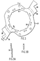
- the two flange plates 31 32 are mirror images of each other and one flange plate 31 is shown in Fig 3.
- the two flange plates 31 and 32 each have a radially inner annular portion 35 with two diametrically opposed radially extending lugs 36 thereon which are formed axially inwardly of the annular portion so that when the two plates 31 and 32 are secured back-to-back on the hub part 30 by rivets 37 the aligned lugs 36 on each plate 31 and 32 abut.
- Relative rotation between the two flywheel masses 11 and 12 is controlled by a plurality of, preferably four, pivotal linkages 40 circumferentially spaced around the flywheel masses, and by two friction damping means 50 located on the inner surface of the wall 13.
- Each pivotal linkage 40 comprises a first link 41 pivotally mounted between the spaced annular portions 35 of the flange plates 31 of the second flywheel mass 12 by way of a pivot 43, and a second link 42 pivotally mounted on the side plates 26 27 of the flywheel mass 11 by way of pivot 44.
- the two links 41 and 42 are pivotally connected to each other by means of a third pivot 45.
- the pivot 43 is positioned radially inwardly of the pivots 44 and 45.
- the first link 41 is formed as a bob weight mass having a greater mass at its end remote from the pivot 43, and adjacent the pivot 45 between the two links 41 and 42.
- the link 41 also has its centre of mass off-set towards its leading edge considering the link 41 relative to its normal drive direction. By off-setting the centre of mass in this manner the centrifugal bob weight effect of the link 41 is increased in the normal drive direction of rotation D.
- the second link 42 comprises a pair of parallel arms which are arranged one on each axial side of the bob weight 41.
- Each pair of arms 42 located one on each axial side of the bob weight 41 extend from the pivot 45 through an aperture 22 in an inclined side of a respective indented area 21 of each side plate 26 27 to connect with a pivot 44 on the axially outer side of said side plates.
- the side plates 26,27 have circumferentially spaced radial slots 23 extending radially outwardly from the inner periphery thereof, to accomodate radial movement of the pivot 45.
- the friction damping means comprise leaf springs 50 (see figs 7 & 8) fixed relative to the outer wall 13 which are deformable by the relative movement of the lugs 36 on the flange plates 31 32. As the flange plates 31 32 move relative to first annular plate 15, the radially outer edges of the lugs 36 cause the leaf springs 50 to deform and resist the movement.
- the springs 50 are so shaped as to provide increasing resistance with increasing relative rotational displacement between the two flywheel masses 11 and 12. The springs are held against movement relative to wall 13 by tangs 50a which engage slots 51 in side plates 26, 27.
- friction damping means could be provided by a stack of friction washers, located on the hub 14 to operate between the annular plate 15 and the hub part 30.
- Alternate friction washers may be driven by the hub 14 of the first flywheel mass 12, and the hub part 30 of the second flywheel mass 12.
- the washers may be urged together by a Belleville spring, such a friction damping means is shown in British Patent Application GB-A-2 198 808.
- Resilient cushioning means 54, 55 are fixed between the side plates 26 27, to cushion the relative movement between the two flywheel masses at the limits of the angular relative rotation.
- the first cushioning means 54 comprise resilient stops, preferably in the form of helical compression springs, which are located on the "drive" side of the lugs 36.
- the springs are located in sets of aligned apertures 28 on the two side plates.
- One end of each spring 54 is held in an end cap 56 fixed at one end of the respective aligned set of apertures 28, and the other end of each springs 54 is located in an end cap 57 which is slideably mounted in the respective set of aligned apertures 28.
- the lugs 36 At the limits of relative rotational movement, in the drive direction the lugs 36 will each abut said end caps 57 and thereafter such movement will be resisted by the springs 54.
- the lugs 36 on the flange plates 31, 32 have notches 38 therein to accomodate a predetermined relative movement between the flywheel mass 11 and 12 before the springs 54 begin to operate.
- the second cushioning means 55 each comprise resilient stops, preferably an elastomeric cylinder, held between two end caps 58 59, and which are located on the "over run" side of the lugs 36.
- the elastomeric cushioning means 55 are located between the end caps 58 59 in second sets of aligned apertures 29 on the two side plates 26, 27. At the limits of relative rotational movement of the flange plates 31 32 in the over-run direction the lugs 36 will each abut a respective end cap 58 which is slideably mounted in the respective apertures 29. Thereafter, further such movement will be resisted by the elastomeric cushioning means.
- the open end of the first flywheel mass 11 is enclosed by a cover plate 60 fixed to the open end of the cylindrical wall 13.
- a resilient seal 61 is clamped between the second flywheel mass 12 and the flange plate 32 and engages the cover plate 60.
- the seal 61 is preferably a sheet metal diaphragm.
- the cavity 'A' may be filled with a viscous clamping medium such as grease.
- the envelope of movement of the bob weights 41 is shown at 40B in Figure 1A.
- the two resilient cushioning means 54, 55 form resilient travel end stops to prevent shock loading in extreme high torque loading conditions when the flywheel masses approach the limit of their permitted relative rotational movement. Such conditions are most likely to occur at low flywheel rotation speeds when the centrifugal controlling force of bob weights 41 is lowest.
- the bob weights 41 are assymetrically shaped having an offset mass to give different effects in the drive direction of relative rotation as compared with the overrun direction of relative rotation.
- the mass is off-set to the leading edge of the bob weight in the drive condition. This has the additional effect of moving the neutral position in the at-rest condition towards the overrun side of the flywheel and gives a longer drive condition travel.
- Figure 9 shows a modified form of cushioning means in which a rubber block 70 is positioned adjacent each end cap 56 in series with each spring 54.
- Each spring 54 acts against a plate 71 which compresses the adjacent rubber block 70.
- plate 71 which compresses block 70.
Landscapes
- Engineering & Computer Science (AREA)
- General Engineering & Computer Science (AREA)
- Mechanical Engineering (AREA)
- Physics & Mathematics (AREA)
- Acoustics & Sound (AREA)
- Aviation & Aerospace Engineering (AREA)
- Mechanical Operated Clutches (AREA)
- Arrangement Or Mounting Of Propulsion Units For Vehicles (AREA)
Abstract
Claims (20)
- Sous-assemblage de volant à deux masses, qui comprend une paire de plaques latérales (26, 27) écartées axialement, qui sont connectées en fonctionnement à une première masse de volant (11), un élément de transmission de force (31, 32) ayant des parties disposées entre les plaques latérales et qui est connecté en fonctionnement à une deuxième masse de volant (12) et plusieurs liaisons (40) interconnectant les plaques latérales (26, 27) et l'élément de transmission de force (31, 32), chaque liaison comprenant un premier élément de liaison (41) connecté à pivot à l'élément de transmission (31, 32), un deuxième élément de liaison (42) connecté à pivot aux plaques latérales (26, 27), et un pivot (45) pour connecter à pivot les premier et deuxième éléments de liaison, lesdites liaisons étant disposées de manière à avoir tendance à s'écarter radialement vers l'extérieur quand le sous-assemblage est en rotation, ce qui permet de régler la rotation relative des plaques latérales et de l'élément de transmission de force.
- Sous-assemblage selon la revendication 1, dans lequel l'élément de transmission de force comprend une paire de plaques de flasque (31, 32) disposées dos à dos.
- Sous-assemblage selon la revendication 1 ou 2, caractérisé en ce que des moyens d'amortissement (54, 55) agissent entre l'élément de transmission de force (31, 32) et la paire de plaques latérales (26, 27) afin de limiter la rotation relative entre eux dans au moins un sens aux limites de ladite rotation relative.
- Sous-assemblage selon la revendication 3, caractérisé en ce que le moyen d'amortissement (54, 55) agit entre les parties marginales radialement externes (36, 28) de l'élément de transmission de force (31, 32) et les plaques latérales (26, 27).
- Sous-assemblage selon la revendication 4, caractérisé en ce que le premier moyen d'amortissement (54) pour un sens de rotation comprend des ressorts de compression et le deuxième moyen d'amortissement (55) pour l'autre sens de rotation comprend des butées en matériau élastomère.
- Sous-assemblage selon la revendication 5, caractérisé en ce que le premier moyen d'amortissement comprend des ressorts de compression (54) et des butées (70) en matériau élastomère, disposées en série.
- Sous-assemblage selon la revendication 2, caractérisé en ce que les plaques de flasque (31, 32) ont chacune une paire de bras (36) faisant saillie radialement vers l'extérieur et diamétralement opposés sur celles-ci, les bras d'une plaque de flasque (31) étant alignés avec les bras de l'autre plaque de flasque (32), et les moyens d'amortissement (54, 55) agissent contre ces bras (36) et sont montés dans des ouvertures (28, 29) alignées dans les plaques latérales (26, 27).
- Sous-assemblage selon la revendication 7, caractérisé en ce que les moyens d'amortissement (54, 55) ont des capuchons d'extrémité (56, 57; 58, 59) sur ceux-ci à chaque extrémité axiale de ceux-ci et les capuchons d'extrémité sont situés dans lesdites plaques latérales (26, 27), pour maintenir en place les moyens d'amortissement (54, 55).
- Sous-assemblage selon l'une quelconque des revendications 1 à 8, caractérisé en ce que les deux plaques latérales (26, 27) ont dans celles-ci des formations alignées essentiellement radiales (23) pour permettre le déplacement d'un pivot correspondant (45) connecté à pivot à un premier élément de liaison (41) et à un deuxième élément de liaison (42) respectivement.
- Sous-assemblage selon l'une quelconque des revendications 1 à 9, caractérisé en ce qu'un élément de liaison (41) de chaque liaison à pivot (40) a une masse plus grande que l'autre élément de liaison (42), si bien qu'un élément de liaison (41) agit comme poids d'équilibrage.
- Sous-assemblage selon la revendication 10, caractérisé en ce que le poids d'équilibrage (41) a une masse décalée par rapport à une ligne joignant le pivot (45) à la connexion à pivot du poids d'équilibrage avec les plaques latérales (26, 27).
- Sous-assemblage selon la revendication 11, dans lequel la masse décalée est décalée vers le bord avant du poids d'équilibrage (41) par rapport au sens de rotation normal de l'entraînement.
- Volant à deux masses (10) pour un véhicule comprenant deux masses de volant (11, 12) disposées co-axialement, qui sont montées pour permettre une rotation angulaire limitée de l'une par rapport à l'autre et un sous-assemblage tel que revendiqué par l'une quelconque des revendications 1 à 12, avec les plaques latérales (26, 27) du sous-assemblage connecté à une masse de volant (11) et l'élément de transmission de force étant connecté à la deuxième masse de volant (12).
- Volant à deux masses selon la revendication 13, caractérisé en ce qu'une masse de volant (11) comprend un moyeu (14), une première plaque annulaire (15) fixée au moyeu et une paroi latérale extérieure cylindrique (13); et la deuxième masse de volant comprend une deuxième plaque annulaire (12) qui est montée sur le moyeu (14) par l'intermédiaire d'un palier (19).
- Volant à deux masses selon la revendication 14, caractérisé en ce que la première plaque annulaire (15) et la paroi latérale extérieure cylindrique (13) forment une cavité annulaire (A) autour du moyeu (14), celle-ci contenant le sous-assemblage conforme à l'une quelconque des revendications 1 à 12, la cavité étant fermée par une plaque de couvercle annulaire (60) fixée à l'extrémité de la paroi latérale (13) à l'écart de la première plaque annulaire (15) et étant remplie par un matériau visqueux pour amortir les déplacements des sous-assemblages dans la cavité.
- Volant à deux masses selon la revendication 15, caractérisé en ce qu'un moyen d'étanchéité élastique (61) agit entre la plaque de couvercle (60) et la deuxième masse de volant (12, 13) pour retenir dans la cavité (A) le matériau visqueux.
- Volant à deux masses selon la revendication 16, caractérisé en ce que le moyen d'étanchéité comprend un diaphragme annulaire en acier à ressort (61).
- Volant à deux masses selon l'une quelconque des revendications 13 à 17, caractérisé en ce qu'un ou plusieurs dispositifs d'amortissement à frottement (50) agissent entre les masses de volant (11, 12) afin de régler leur rotation angulaire relative.
- Volant à deux masses selon la revendication 18, caractérisé en ce que les dispositifs d'amortissement de frottement comprennent des ressorts à lame (50) ayant des parties surélevées pouvant venir en contact avec l'élément de transmission de force (31, 32) après une rotation angulaire relative prédéterminée.
- Volant à deux masses selon l'une quelconque des revendications 14 à 19 quand elles dépendent de la revendication 3, caractérisé en ce que les moyens d'amortissement (54, 55) sont disposés à proximité de la paroi cylindrique (13).
Applications Claiming Priority (3)
| Application Number | Priority Date | Filing Date | Title |
|---|---|---|---|
| GB939304578A GB9304578D0 (en) | 1993-03-05 | 1993-03-05 | A twin flywheel |
| GB9304578 | 1993-03-05 | ||
| PCT/GB1994/000422 WO1994020769A1 (fr) | 1993-03-05 | 1994-03-04 | Volant a deux masses |
Publications (2)
| Publication Number | Publication Date |
|---|---|
| EP0639247A1 EP0639247A1 (fr) | 1995-02-22 |
| EP0639247B1 true EP0639247B1 (fr) | 1997-07-30 |
Family
ID=10731573
Family Applications (1)
| Application Number | Title | Priority Date | Filing Date |
|---|---|---|---|
| EP94908425A Expired - Lifetime EP0639247B1 (fr) | 1993-03-05 | 1994-03-04 | Volant a deux masses |
Country Status (6)
| Country | Link |
|---|---|
| US (1) | US5697845A (fr) |
| EP (1) | EP0639247B1 (fr) |
| JP (1) | JPH08507133A (fr) |
| DE (1) | DE69404572T2 (fr) |
| GB (2) | GB9304578D0 (fr) |
| WO (1) | WO1994020769A1 (fr) |
Families Citing this family (24)
| Publication number | Priority date | Publication date | Assignee | Title |
|---|---|---|---|---|
| GB2284038B (en) * | 1991-01-30 | 1995-08-16 | Automotive Products Plc | Twin mass flywheel |
| WO1996006289A1 (fr) * | 1994-08-20 | 1996-02-29 | Automotive Products Plc | Volant d'inertie a double masse |
| GB2297821B (en) * | 1994-08-20 | 1998-06-17 | Automotive Products Plc | Twin mass flywheel |
| GB9505750D0 (en) * | 1995-03-21 | 1995-05-10 | Automotive Products Plc | A twin mass flywheel friction damping device |
| GB9511080D0 (en) * | 1995-06-01 | 1995-07-26 | Automotive Products Plc | Twin mass flywheel |
| DE19635797C2 (de) * | 1996-06-12 | 2003-02-27 | Zf Sachs Ag | Torsionsschwingungsdämpfer mit Wälzkörpern als Koppelelemente |
| JP3839874B2 (ja) * | 1996-07-10 | 2006-11-01 | 株式会社エクセディ | フライホイール組立体 |
| JPH1026185A (ja) * | 1996-07-10 | 1998-01-27 | Exedy Corp | フライホイール組立体 |
| DE19713132A1 (de) * | 1997-03-27 | 1998-10-01 | Mannesmann Sachs Ag | Torsionsschwingungsdämpfer |
| GB2329448B (en) * | 1997-03-27 | 2001-09-26 | Automotive Products Plc | Torsional vibration dampers |
| AU7345098A (en) * | 1997-05-09 | 1998-12-08 | Automotive Products Plc | Twin mass flywheels |
| DE19752667C2 (de) * | 1997-11-27 | 2000-06-08 | Mannesmann Sachs Ag | Drehschwingungsdämpfer |
| GB2339005B (en) | 1998-02-13 | 2002-08-28 | Automotive Products Plc | Torsional vibration dampers |
| GB2339268B (en) * | 1998-02-13 | 2002-12-18 | Automotive Products Plc | Torsional vibration dampers |
| GB2340204B (en) * | 1998-02-13 | 2002-07-24 | Automotive Products Plc | A damping device |
| GB9803048D0 (en) * | 1998-02-13 | 1998-04-08 | Automotive Products Plc | A damping device |
| US6402621B1 (en) | 1998-02-13 | 2002-06-11 | Ap Atm Limited | Torsional vibration dampers |
| DE19816518B4 (de) * | 1998-04-14 | 2007-07-26 | Zf Sachs Ag | Torsionsschwingungsdämpfer mit einer strömungsbildenden Einrichtung |
| DE19831158A1 (de) * | 1998-07-11 | 2000-01-13 | Freudenberg Carl Fa | Schwungrad |
| GB2343233A (en) * | 1998-10-28 | 2000-05-03 | Whitnash Plc | Torsional vibration damper. |
| GB9919410D0 (en) * | 1999-08-18 | 1999-10-20 | Whitnash Plc | Torsional vibration dampers |
| FR2862730B1 (fr) * | 2003-11-24 | 2007-02-16 | Valeo Embrayages | Amortisseur de torsion pour dispositif de transmission de couple |
| DE102010029464A1 (de) * | 2010-05-28 | 2011-12-01 | Zf Friedrichshafen Ag | Torsionsschwingungsdämpferanordnung und Schwingungsdämpfereinrichtung, insbesondere in einer Torsionsschwingungsdämpferanordnung |
| IT201900018479A1 (it) * | 2019-10-10 | 2021-04-10 | Lusetti Lea | Un volano con avviamento automatico e relativo metodo |
Family Cites Families (14)
| Publication number | Priority date | Publication date | Assignee | Title |
|---|---|---|---|---|
| US2667049A (en) * | 1950-02-02 | 1954-01-26 | Gen Motors Corp | Torsional vibration isolating coupling |
| GB1194368A (en) * | 1966-07-15 | 1970-06-10 | Daimler Benz Ag | Improvements relating to Apparatus for Controlling the Commencement of Injection in Injection Type Internal Combustion Engines. |
| JPS513928B2 (fr) * | 1972-12-21 | 1976-02-06 | ||
| FR2361574A1 (fr) * | 1976-08-09 | 1978-03-10 | Ferodo Sa | Dispositif amortisseur de torsion, en particulier friction d'embrayage notamment pour vehicule automobile |
| DE3505677A1 (de) * | 1985-02-19 | 1986-08-21 | Fichtel & Sachs Ag, 8720 Schweinfurt | Geteiltes schwungrad mit abschaltbarer reibeinrichtung |
| FR2593252B1 (fr) * | 1986-01-22 | 1990-09-07 | Valeo | Volant amortisseur pour transmission, notamment pour vehicule automobile |
| FR2602560B1 (fr) * | 1986-08-06 | 1990-11-02 | Valeo | Unite d'embrayage, et applications notamment friction d'embrayage, embrayage et organe d'accouplement hydraulique comportant une telle unite, en particulier pour vehicule automobile |
| GB2198808A (en) * | 1986-12-05 | 1988-06-22 | Automotive Products Plc | Friction clutch driven plates |
| DE3708345A1 (de) * | 1987-03-14 | 1988-09-29 | Voith Gmbh J M | Elastische kupplung |
| WO1989001097A1 (fr) * | 1987-07-25 | 1989-02-09 | Automotive Products Plc | Agencement de transmission du couple |
| DE3733544A1 (de) * | 1987-10-03 | 1989-04-13 | Fichtel & Sachs Ag | Torsionsschwingungsdaempfer mit vom uebertragenen drehmoment abhaengiger reibeinrichtung |
| DE3841363A1 (de) * | 1988-12-08 | 1990-06-13 | Fichtel & Sachs Ag | Anordnung eines torsionsschwingungsdaempfers innerhalb eines zwei-massen-systems |
| JPH0756318B2 (ja) * | 1990-10-29 | 1995-06-14 | 株式会社大金製作所 | 液体粘性ダンパー |
| GB2284038B (en) * | 1991-01-30 | 1995-08-16 | Automotive Products Plc | Twin mass flywheel |
-
1993
- 1993-03-05 GB GB939304578A patent/GB9304578D0/en active Pending
-
1994
- 1994-03-04 DE DE69404572T patent/DE69404572T2/de not_active Expired - Fee Related
- 1994-03-04 JP JP6519726A patent/JPH08507133A/ja active Pending
- 1994-03-04 WO PCT/GB1994/000422 patent/WO1994020769A1/fr not_active Ceased
- 1994-03-04 GB GB9421900A patent/GB2282868B/en not_active Expired - Fee Related
- 1994-03-04 US US08/331,494 patent/US5697845A/en not_active Expired - Fee Related
- 1994-03-04 EP EP94908425A patent/EP0639247B1/fr not_active Expired - Lifetime
Also Published As
| Publication number | Publication date |
|---|---|
| DE69404572D1 (de) | 1997-09-04 |
| GB2282868A (en) | 1995-04-19 |
| US5697845A (en) | 1997-12-16 |
| GB9304578D0 (en) | 1993-04-21 |
| GB2282868B (en) | 1997-04-02 |
| WO1994020769A1 (fr) | 1994-09-15 |
| EP0639247A1 (fr) | 1995-02-22 |
| GB9421900D0 (en) | 1995-01-25 |
| DE69404572T2 (de) | 1998-01-02 |
| JPH08507133A (ja) | 1996-07-30 |
Similar Documents
| Publication | Publication Date | Title |
|---|---|---|
| US5697845A (en) | Twin mass flywheel sub-assembly for a motor vehicle | |
| US5557984A (en) | Twin mass flywheel | |
| EP0909906B1 (fr) | Dispositif d'amortissement à friction de volant d'inertie à double masse | |
| US5032107A (en) | Flywheel device with a torsional damper | |
| US20060178220A1 (en) | Torsional vibration damper | |
| EP0723635B1 (fr) | Volant d'inertie a double masse | |
| US6029539A (en) | Twin mass flywheel | |
| JPS6353335A (ja) | トルク伝達システム用ねじり振動減衰装置 | |
| GB2315112A (en) | Torsional vibration damper having a cancelling mass and compensating flywheel | |
| WO1989001097A1 (fr) | Agencement de transmission du couple | |
| EP1626198B1 (fr) | Amortisseur de vibrations de torsion | |
| US5025680A (en) | Torsional damper type flywheel device | |
| JP2000130513A (ja) | ねじり振動減衰装置 | |
| EP1626197B1 (fr) | Amortisseur de vibrations torsionelles | |
| WO1999041522A1 (fr) | Dispositif amortisseur | |
| EP0617773B1 (fr) | Volant d'inertie double | |
| US5194046A (en) | Damper type flywheel assembly with at least one substantially segment-shaped member | |
| US5713796A (en) | Flywheel assembly and its method of assembly | |
| EP1434954A1 (fr) | Amortisseurs de vibrations de torsion | |
| JPH0647152Y2 (ja) | トルク変動吸収装置 | |
| GB2329690A (en) | Twin mass flywheel friction damping device |
Legal Events
| Date | Code | Title | Description |
|---|---|---|---|
| PUAI | Public reference made under article 153(3) epc to a published international application that has entered the european phase |
Free format text: ORIGINAL CODE: 0009012 |
|
| 17P | Request for examination filed |
Effective date: 19941031 |
|
| AK | Designated contracting states |
Kind code of ref document: A1 Designated state(s): DE FR GB IT |
|
| 17Q | First examination report despatched |
Effective date: 19951221 |
|
| GRAG | Despatch of communication of intention to grant |
Free format text: ORIGINAL CODE: EPIDOS AGRA |
|
| GRAH | Despatch of communication of intention to grant a patent |
Free format text: ORIGINAL CODE: EPIDOS IGRA |
|
| GRAH | Despatch of communication of intention to grant a patent |
Free format text: ORIGINAL CODE: EPIDOS IGRA |
|
| GRAA | (expected) grant |
Free format text: ORIGINAL CODE: 0009210 |
|
| AK | Designated contracting states |
Kind code of ref document: B1 Designated state(s): DE FR GB IT |
|
| REF | Corresponds to: |
Ref document number: 69404572 Country of ref document: DE Date of ref document: 19970904 |
|
| ET | Fr: translation filed | ||
| ITF | It: translation for a ep patent filed | ||
| PLBE | No opposition filed within time limit |
Free format text: ORIGINAL CODE: 0009261 |
|
| STAA | Information on the status of an ep patent application or granted ep patent |
Free format text: STATUS: NO OPPOSITION FILED WITHIN TIME LIMIT |
|
| 26N | No opposition filed | ||
| REG | Reference to a national code |
Ref country code: GB Ref legal event code: 732E |
|
| REG | Reference to a national code |
Ref country code: GB Ref legal event code: IF02 |
|
| PGFP | Annual fee paid to national office [announced via postgrant information from national office to epo] |
Ref country code: FR Payment date: 20020311 Year of fee payment: 9 |
|
| PGFP | Annual fee paid to national office [announced via postgrant information from national office to epo] |
Ref country code: GB Payment date: 20020313 Year of fee payment: 9 |
|
| PGFP | Annual fee paid to national office [announced via postgrant information from national office to epo] |
Ref country code: DE Payment date: 20020315 Year of fee payment: 9 |
|
| PG25 | Lapsed in a contracting state [announced via postgrant information from national office to epo] |
Ref country code: GB Free format text: LAPSE BECAUSE OF NON-PAYMENT OF DUE FEES Effective date: 20030304 |
|
| PG25 | Lapsed in a contracting state [announced via postgrant information from national office to epo] |
Ref country code: DE Free format text: LAPSE BECAUSE OF NON-PAYMENT OF DUE FEES Effective date: 20031001 |
|
| GBPC | Gb: european patent ceased through non-payment of renewal fee | ||
| PG25 | Lapsed in a contracting state [announced via postgrant information from national office to epo] |
Ref country code: FR Free format text: LAPSE BECAUSE OF NON-PAYMENT OF DUE FEES Effective date: 20031127 |
|
| REG | Reference to a national code |
Ref country code: FR Ref legal event code: ST |
|
| PG25 | Lapsed in a contracting state [announced via postgrant information from national office to epo] |
Ref country code: IT Free format text: LAPSE BECAUSE OF NON-PAYMENT OF DUE FEES Effective date: 20050304 |