EP0639711A2 - Commande du cliquetis d'un moteur par machine d'inférence - Google Patents
Commande du cliquetis d'un moteur par machine d'inférence Download PDFInfo
- Publication number
- EP0639711A2 EP0639711A2 EP94202087A EP94202087A EP0639711A2 EP 0639711 A2 EP0639711 A2 EP 0639711A2 EP 94202087 A EP94202087 A EP 94202087A EP 94202087 A EP94202087 A EP 94202087A EP 0639711 A2 EP0639711 A2 EP 0639711A2
- Authority
- EP
- European Patent Office
- Prior art keywords
- engine
- knock
- spark retard
- sensed
- truths
- Prior art date
- Legal status (The legal status is an assumption and is not a legal conclusion. Google has not performed a legal analysis and makes no representation as to the accuracy of the status listed.)
- Granted
Links
- 230000006870 function Effects 0.000 claims abstract description 47
- 230000004044 response Effects 0.000 claims abstract description 13
- 238000002485 combustion reaction Methods 0.000 claims abstract description 8
- 238000000034 method Methods 0.000 claims description 20
- 239000002826 coolant Substances 0.000 description 9
- 239000000446 fuel Substances 0.000 description 7
- 230000003044 adaptive effect Effects 0.000 description 6
- 238000001514 detection method Methods 0.000 description 5
- 230000008569 process Effects 0.000 description 5
- 238000013459 approach Methods 0.000 description 4
- 238000004458 analytical method Methods 0.000 description 3
- 230000003247 decreasing effect Effects 0.000 description 3
- 230000000737 periodic effect Effects 0.000 description 3
- 230000005855 radiation Effects 0.000 description 3
- 230000005540 biological transmission Effects 0.000 description 2
- 230000008859 change Effects 0.000 description 2
- 238000013461 design Methods 0.000 description 2
- 238000012545 processing Methods 0.000 description 2
- 230000006399 behavior Effects 0.000 description 1
- 238000013500 data storage Methods 0.000 description 1
- 230000007423 decrease Effects 0.000 description 1
- 230000000593 degrading effect Effects 0.000 description 1
- 230000001627 detrimental effect Effects 0.000 description 1
- 238000010586 diagram Methods 0.000 description 1
- 230000000694 effects Effects 0.000 description 1
- 239000003344 environmental pollutant Substances 0.000 description 1
- 238000011156 evaluation Methods 0.000 description 1
- 238000001914 filtration Methods 0.000 description 1
- 230000003993 interaction Effects 0.000 description 1
- 238000010606 normalization Methods 0.000 description 1
- 231100000719 pollutant Toxicity 0.000 description 1
- 230000009467 reduction Effects 0.000 description 1
- 230000000717 retained effect Effects 0.000 description 1
- 238000005070 sampling Methods 0.000 description 1
- 230000035945 sensitivity Effects 0.000 description 1
- 238000012360 testing method Methods 0.000 description 1
- 230000009466 transformation Effects 0.000 description 1
Images




Classifications
-
- F—MECHANICAL ENGINEERING; LIGHTING; HEATING; WEAPONS; BLASTING
- F02—COMBUSTION ENGINES; HOT-GAS OR COMBUSTION-PRODUCT ENGINE PLANTS
- F02P—IGNITION, OTHER THAN COMPRESSION IGNITION, FOR INTERNAL-COMBUSTION ENGINES; TESTING OF IGNITION TIMING IN COMPRESSION-IGNITION ENGINES
- F02P5/00—Advancing or retarding ignition; Control therefor
- F02P5/04—Advancing or retarding ignition; Control therefor automatically, as a function of the working conditions of the engine or vehicle or of the atmospheric conditions
- F02P5/145—Advancing or retarding ignition; Control therefor automatically, as a function of the working conditions of the engine or vehicle or of the atmospheric conditions using electrical means
- F02P5/15—Digital data processing
- F02P5/152—Digital data processing dependent on pinking
-
- G—PHYSICS
- G05—CONTROLLING; REGULATING
- G05B—CONTROL OR REGULATING SYSTEMS IN GENERAL; FUNCTIONAL ELEMENTS OF SUCH SYSTEMS; MONITORING OR TESTING ARRANGEMENTS FOR SUCH SYSTEMS OR ELEMENTS
- G05B13/00—Adaptive control systems, i.e. systems automatically adjusting themselves to have a performance which is optimum according to some preassigned criterion
- G05B13/02—Adaptive control systems, i.e. systems automatically adjusting themselves to have a performance which is optimum according to some preassigned criterion electric
- G05B13/0265—Adaptive control systems, i.e. systems automatically adjusting themselves to have a performance which is optimum according to some preassigned criterion electric the criterion being a learning criterion
- G05B13/0275—Adaptive control systems, i.e. systems automatically adjusting themselves to have a performance which is optimum according to some preassigned criterion electric the criterion being a learning criterion using fuzzy logic only
-
- Y—GENERAL TAGGING OF NEW TECHNOLOGICAL DEVELOPMENTS; GENERAL TAGGING OF CROSS-SECTIONAL TECHNOLOGIES SPANNING OVER SEVERAL SECTIONS OF THE IPC; TECHNICAL SUBJECTS COVERED BY FORMER USPC CROSS-REFERENCE ART COLLECTIONS [XRACs] AND DIGESTS
- Y02—TECHNOLOGIES OR APPLICATIONS FOR MITIGATION OR ADAPTATION AGAINST CLIMATE CHANGE
- Y02T—CLIMATE CHANGE MITIGATION TECHNOLOGIES RELATED TO TRANSPORTATION
- Y02T10/00—Road transport of goods or passengers
- Y02T10/10—Internal combustion engine [ICE] based vehicles
- Y02T10/40—Engine management systems
Definitions
- This invention relates to a method of controlling ignition timing and to a method of modifying internal combustion engine timing.
- Detection of cylinder knock in internal combustion engines is known. For example, it is known that the amplitude and duration of engine vibration at certain frequencies can indicate the presence of cylinder knock. Accordingly, conventional knock detection approaches may measure radiation from the engine at certain calibrated frequencies and diagnose knock from the duration and magnitude of such radiation. Spark timing adjustments are made in a manner as to reduce or eliminate the diagnosed knock. Such adjustments generally compromise other control goals, such as engine performance or fuel economy and thus should be made with discretion. For example, such adjustments should only be made when truly needed to mitigate the well-known negative effects of knock. Accurate knock detection is therefore desirable to diagnose when spark timing adjustments are truly needed.
- the present invention seeks to provide an improved method of controlling ignition timing.
- a plurality of engine operating parameters are sensed and normalised via a set of weighted membership functions.
- the normalised parameters are passed through an engine model (inference engine) according to a predetermined rule base to form a set of truths, each of which provides information on engine knock tendency.
- the truths are individually positioned according to their individual potential to contribute misleading knock information and are weighted with respect to each other to indicate the magnitude of their relative contributions to the estimate of knock tendency.
- the positioned, weighted truths are then combined to form a knock confidence value, the magnitude of which indicates the degree of confidence which should be placed in any sensed knock condition for the set of sensed engine operating parameters.
- the knock confidence value may be used to adjust a knock based ignition retard signal to reflect the determined level of confidence that such retard is appropriate.
- the knock confidence value may be used in adaptive spark retard in which knock based retard values are learned, stored and adjusted over the life of the engine as a function of engine operating level, by adjusting the degree of learning in response to the confidence value.
- an internal combustion engine 10 is provided with intake air and fuel through an intake manifold 14, from which manifold air temperature MAT is measured by a conventional manifold absolute temperature sensor 16 and manifold absolute air pressure MAP is measured by a conventional MAP sensor 18.
- Disc 40 rotates with an engine output shaft such as an engine crankshaft (not shown), with conventional variable reluctance sensor 42 positioned to sense the passage of teeth on disc 40 and to output a periodic signal RPM having a frequency proportional to the rate of rotation of disc 40 and thus of the engine output shaft.
- Temperature sensor 20, such as a conventional thermocouple, is located on the engine in position to sense engine coolant temperature and to output a signal TEMP indicative thereof.
- Knock sensor 22 is provided, which may be any vibration or other sensor for producing a signal of a knock related engine parameter, such as a sensor for sensing engine vibration radiation within a predetermined frequency range.
- Sensor 22 outputs a signal to knock processor 24 which is designed to reduce substantially the noise in the output signal of sensor 22 by generating a knock signal KNOCKCNT, which may be in the form of a counter value periodically cleared and incremented upon each identification of a sensed knock event by sensor 22.
- Engine controller 26 includes such conventionally known elements as a central processing unit CPU 28 and data storage units including read only memory ROM 32, random access memory RAM 34 and non-volatile random access memory NVRAM 30.
- the engine controller 26 processes such input signals as MAT, MAP, TEMP, KNOCKCNT and RPM and generates output commands for engine control actuators, for example to control fuel, air and spark to engine 10.
- the control of fuel and air to the engine may be carried out in a conventional manner, for example, to maintain an air/fuel ratio consistent with a desired engine performance, fuel economy and level of engine exhaust gas pollutants.
- the control of the timing of the conventional spark command issued by engine controller 26 in this embodiment is computed in accordance with the routines of Figures 2A, 2B and 3.
- Engine controller 26 periodically executes these routines when SPARK COMMAND is to be computed, in a manner generally understood in ignition control.
- SPARK COMMAND once computed, is stored in engine controller memory, such as RAM 34 and is issued to IGNITION CONTROLLER 36 when at least one of spark plugs 38 is to be ignited. Ignition may be provided on the basis of engine angular position as indicated by the signal RPM, in accordance with well-known engine control practice.
- IGNITION CONTROLLER 36 conditions SPARK COMMAND and provides appropriate commands to appropriate members of spark plugs 38, as is generally known in the art.
- the ignition control of the preferred embodiment responds to a sensed engine knock condition and to an estimate of engine knock tendency to adjust spark timing for knock minimisation.
- such operations are carried out by a series of steps executed by engine controller 26, such as by a series of operations stored in ROM 32 and periodically carried out by engine controller 26, such as every 12.5 milliseconds while the engine controller is operating.
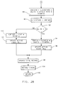
- Step 60 of Figure 2A the routine then moves to step 62 to read the present value of input signals, such as KNOCKCNT, TEMP, MAP, RPM and MAT.
- input signals such as KNOCKCNT, TEMP, MAP, RPM and MAT.
- the signal KNOCKCNT may be filtered by a timing window in the engine controller 26 before use by the routine of Figures 2A and 2B, such as described in US-A-5,163,404, in which the engine controller would selectively filter KNOCKCNT from knock processor 24 based on a relationship between the engine position at the occurrence of the knock condition and an engine position window measured from cylinder top dead centre TDC.
- the routine moves to step 64 to determine basic ignition timing in a manner generally understood in the art, for example as a function of RPM, MAP and other sensed operating inputs from engine 10.
- the basic ignition timing may be a value derived from a look-up table in ROM 32 obtained from a two-dimensional array based on RPM and MAP, using the present sensed RPM and MAP signals.
- the obtained timing value may be modified by other engine operating parameters, such as TEMP, fuel composition, as is generally known in the art.
- This basic ignition timing may be expressed for convenience in degrees after cylinder TDC of the present engine cylinder to be ignited.
- a change in knock value DELTAK is computed at step 66, as proportional to the difference between the present knock count KNOCKCNT and OLDKNOCKCNT, which is the knock count from the previous pass through the routine of Figures 2A and 2B.
- DELTAK indicates any new sensed potential engine knock condition.
- the present KNOCKCNT is stored as OLDKNOCKCNT at step 68.
- the routine then proceeds to step 70 to determine ATTACK RATE as the conversion factor to compute degree of knock retard from change in sensed knock counts, using generally known relationships between knock and spark retard. It is generally known that the ATTACK RATE may be determined as a function of engine speed RPM, such as from a look-up table in ROM 32.
- the routine moves to steps 72-88 to determine a degree of retard appropriate for the present sensed knock condition.
- FIG. 4-13 illustrate a set of membership functions used in this embodiment.
- the membership functions consistent with conventional fuzzy logic control, subdivide the input signals into categories in accordance with the domain of a predetermined rule base and normalise the input signals within each category.
- the rule base required the following membership function categories: Input Signal Category Variable Name TEMP Low temp. LOCT High temp. HICT Not low temp. NOTLOCT MAP Low pressure LOMAP High pressure HIMAP RPM Low speed LORPM High speed HIRPM TOTAL RETARD Low Retard LORETARD High Retard HIRETARD MAT High air temp.
- HIMAT Input Signal Category Variable Name TEMP Low temp. LOCT High temp. HICT Not low temp.
- NOTLOCT MAP Low pressure LOMAP High pressure
- HIMAT Input Signal Category Variable Name TEM
- the magnitude of the output of the membership functions indicates the strength of "membership" in the corresponding category.
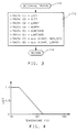
- the magnitude of the low coolant temperature membership function output LOCT indicates generally how low coolant temperature is within a low temperature range, as illustrated in Figure 4.
- Figure 5 illustrates such a relationship in a high coolant temperature range, as reflected in the magnitude of the output of the high coolant temperature membership function HICT.
- the degree by which sensed coolant temperature TEMP is not within the low range is indicated by the output magnitude of the "not low" coolant temperature membership function NOTLOCT, as illustrated in Figure 6.
- membership function having output LOMAP indicates the degree of "membership" of MAP within a low pressure range, as illustrated in Figure 7
- membership function having output HIMAP indicates the degree of "membership” of MAP within a high pressure range, as illustrated in Figure 8.
- Two membership functions attempt to quantify engine speed RPM for application to the rule base of the inference engine of the described embodiment. These include the membership function having output LORPM, which indicates the degree of "membership” of RPM within a low engine speed range, as illustrated in Figure 9 and the membership function having output HIRPM, which indicates the degree of "membership” of RPM within a high engine speed range as illustrated in Figure 10.
- Total engine spark retard TOTAL RETARD is assigned two categories in accordance with the needs of the rule base of the inference engine considered with the described embodiment. Specifically, the membership function having output HIRETARD indicates a degree of "membership" of TOTAL RETARD within a high total spark retard range as illustrated in Figure 11 and the membership function having output LORETARD indicates a degree of "membership” of TOTAL RETARD within a low total spark retard range as illustrated in Figure 12.
- TOTAL RETARD is an aggregate of all contributions to spark retard in the engine, including knock based retard.
- the most recently computed TOTAL RETARD such as that computed in the previous pass through the routine of Figures 2A and 2B, may be used in the TOTAL RETARD membership functions.
- manifold air temperature MAT has a single category assigned to it for application to the rule base of the inference engine under consideration, in which the membership function having output HIMAT indicates the degree of "membership" of MAT in a high temperature range, as illustrated in Figure 13.
- step 74 to apply the membership functions to a knowledge rule base to determine a set of associated truths, in accordance with conventional fuzzy logic based control practice.
- the transformation of the membership functions into a set of truths is set out in Figure 3, described below.
- the rules forming the rule base used to transform the membership functions is determined in an analysis of the impact of the membership functions on engine knock tendency, for example, by analysing engine knock tendency while varying selected engine input signals in a controlled test environment and recording engine knock sensitivity as a function of each of the varied engine input signals or combinations of signals.
- step 76 initialise local variables used to compute a confidence value indicative of engine knock tendency for the present pass through the routine of Figures 2A and 2B. Specifically, at step 76, index "n" is set to one and variables NUM and DENOM are cleared.
- the routine then moves to steps 78 to 86 to compute KCONFID as a weighted sum of the truths determined at step 74.
- the routine first moves to step 78 to determine if the index "n" exceeds eight, the number of truths to be included in the computation in this embodiment. If "n" exceeds eight, the routine moves to step 86, to be described.
- the position values may be determined in a calibration step as the extent by which the associated truth indicates engine knock tendency.
- the position values are normalised between 0 and 10, in which a truth having a low value, such as zero would indicate an engine operating condition associated with a low knock tendency and a truth having a high value, such as ten would indicate an engine operating condition associated with a high knock tendency.
- the weighting values are used to weight the truths with respect to each other to reflect any variance in the degree by which the rules indicate a knock tendency.
- the weights are normalised between zero and ten, in which a weight near zero indicates the associated truth provides little indication of engine knock tendency and can be easily overcome by another truth having a higher weight, while a weight of ten indicates the associated truth provides much information on engine knock tendency compared to the other truths.
- the following are representative position and weight values for associated truths TRUTH POSITION WEIGHT 1 0 10 2 7.5 2.5 3 0 10 4 2.5 2 5 0 10 6 8 2 7 10 2.5 8 10 2.5 in which the truths are defined in Figure 3.
- the seventh and eighth truths have positions of ten, indicating maximum knock tendency in the presence of the seventh or eighth truths.
- these truths have relatively low weights of 2.5, indicating they are relatively weak when compared to any other truths which may be present for indicating knock.
- any truth which is present in comparable magnitude and with a high weight value, such as the first, third, or fifth truths would be predominant over the seventh or eighth truths.
- KCONFID is normalised between zero and one and generally reflects a normalisation of the POS() input, in which a KCONFID value of zero indicates that, according to the entire rule base, the present engine operating level is associated with virtually no tendency for engine knock, while a value of one indicates that, according to the entire rule base, the engine operating level is associated with a very high tendency for engine knock.
- any knock condition sensed according to conventional knock sensing techniques may be reduced by KCONFID before being used to determine an appropriate degree of knock based spark retard or before being applied in an adaptive knock control technique.
- KRETARD OLDKRETARD + DELTAK * ATTACK RATE * KCONFID in which OLDKRETARD is the knock based spark retard as determined in the previous pass through the routine of Figures 2A and 2B and as periodically decayed towards zero retard, as described.
- KCONFID the degree by which the knock based spark retard is adjusted in response to a sensed potential knock condition
- KCONFID in which full adjustment is permitted when knock confidence is high, but the amount of adjustment is decreased as KCONFID decreases and no retard adjustment is permitted when KCONFID is zero, indicating engine knock will normally not occur at the current engine operating level.
- step 90 the routine moves to step 90 to update OLDKRETARD as KRETARD.
- this value will be periodically decayed towards zero retard, such as by a time based interrupt driven routine. For example, in this embodiment, approximately every 100 milliseconds while the engine controller 26 is operating, the value stored as OLDKRETARD will be decreased by 26 percent of its magnitude to decay knock based retard towards zero.
- the routine in which OLDKRETARD is decayed in this embodiment is not illustrated, but may be a series of instructions stored in ROM 32 which are executed upon occurrence of a periodic time base engine controller interrupt.
- step 92 determines if any potential engine knock condition was sensed for the present pass through the routine of Figures 2A and 2B as would be reflected in an increase in KNOCKCNT, as described at step 66. If DELTAK does not exceed zero, indicating no increase in KNOCKCNT since the last pass through the routine of Figures 2A and 2B, the routine moves to steps 100-102 and 94-96 to apply the determined knock confidence value in an adaptive learned knock based spark retard approach, which may be any conventional spark retard learning algorithm.
- a series of cells are defined as a function of an engine operating level, such as engine speed and engine load.
- Knock based spark retard values are stored for each of the cells in non-volatile memory NVRAM 30 and are adjusted as necessary in response to sensed knock conditions.
- the learned retard from an active cell is applied in a feedforward manner to adjust ignition timing accordingly.
- the learned retard in the active cell is slowly decreased, for example according to a predetermined decay rate, to minimise unnecessary retard.
- the spark retard may be increased in proportion to the magnitude or duration of the sensed knock condition.
- the determined confidence value KCONFID may be used to affect the degree of learning in the active cell, in accordance with the degree of confidence in the sensed knock condition which traditionally controlled the degree of learning.
- Steps 100-102 of Figure 2B illustrate how this learning occurs in the absence of a sensed knock condition in the preferred embodiment and steps 94-96, to be described, illustrate how this learning is carried out in the presence of a sensed knock condition.
- step 102 updates the present active cell in accordance with the determined ADPTOUT value.
- the routine then moves to step 98, to be described.
- KTHRESH is used to limit learning of retard to only more significant sensed knock conditions, as it is assumed that minor knock conditions, such as those less than KTHRESH, can be acceptably compensated without resort to the present adaptive approach.
- step 96 the routine moves to step 96 to update the present active cell in accordance with the determined ADPTIN value.
- the routine then proceeds to step 98 to update TOTAL RETARD which may, as is generally known in the art, be a sum of such retard components as KRETARD, any retard value stored in the present active cell and other conventionally known retard values responsive to such engine parameters as engine coolant temperature TEMP, manifold air temperature MAT, transmission based retard, such as may be required during a transmission upshift or traction control based retard.
- step 104 the routine moves to step 104 to apply TOTAL RETARD to a spark timing command to retard ignition timing accordingly.
- the spark timing command as retarded through the steps of Figures 2A and 2B will be applied to ignite appropriate spark plugs of engine 10.
- step 106 After having retarded timing at step 104, the routine moves to step 106 to return to any routine which may have been operating at the time it was initiated.
- the routine of Figures 2A and 2B will periodically, for example on a time base of approximately 12.5 milliseconds, be re-executed to update TOTAL RETARD so as to reflect any evolving engine needs.
- the steps of Figure 3 are executed as called from step 74 of Figure 2A to determine a set of truths by passing the membership functions through the engine model.
- the routine of Figure 3 once called from step 74 of the routine of Figure 2A, starts at step 110 and moves directly to a list of rules at step 112, in which rules 1 to 6 are simply the membership functions shown, passed directly through the inference engine to become truths 1 to 6.
- TRUTH(7) min(HIMAT, NOTLOCT) which is consistent with rule form known generally in fuzzy logic design, in which the value assigned to the truth is the minimum value of a predetermined group of membership functions.
- unique information on engine knock tendency may be derived from a combination of manifold air temperature MAT and engine coolant temperature TEMP.
- an appropriate rule such as the rule defining TRUTH(7), such information may be incorporated into an estimate of engine knock tendency in a precise manner.
- TRUTH(7) provides that the membership functions HIMAT, from Figure 13 and NOTLOCT from Figure 6, interact in such a way that the smaller of the two membership functions defines the strength or magnitude of TRUTH(7).
- TRUTH (8) min(HIMAP, LORPM) in which the magnitude of TRUTH(8) is defined as the minimum of the magnitudes of HIMAP as illustrated in Figure 8 and LORPM as illustrated in Figure 9.
- the routine of Figure 3 After defining the eight TRUTHS in the inference engine, the routine of Figure 3 returns, via step 114, to the routine of Figure 2.
Landscapes
- Engineering & Computer Science (AREA)
- Artificial Intelligence (AREA)
- Software Systems (AREA)
- Physics & Mathematics (AREA)
- Evolutionary Computation (AREA)
- Automation & Control Theory (AREA)
- Health & Medical Sciences (AREA)
- Computer Vision & Pattern Recognition (AREA)
- Fuzzy Systems (AREA)
- Medical Informatics (AREA)
- General Physics & Mathematics (AREA)
- Mathematical Physics (AREA)
- Signal Processing (AREA)
- Chemical & Material Sciences (AREA)
- Combustion & Propulsion (AREA)
- Mechanical Engineering (AREA)
- General Engineering & Computer Science (AREA)
- Electrical Control Of Ignition Timing (AREA)
- Combined Controls Of Internal Combustion Engines (AREA)
Applications Claiming Priority (2)
| Application Number | Priority Date | Filing Date | Title |
|---|---|---|---|
| US106842 | 1993-08-16 | ||
| US08/106,842 US5560337A (en) | 1993-08-16 | 1993-08-16 | Knock control using fuzzy logic |
Publications (3)
| Publication Number | Publication Date |
|---|---|
| EP0639711A2 true EP0639711A2 (fr) | 1995-02-22 |
| EP0639711A3 EP0639711A3 (fr) | 1996-01-24 |
| EP0639711B1 EP0639711B1 (fr) | 2003-02-12 |
Family
ID=22313555
Family Applications (1)
| Application Number | Title | Priority Date | Filing Date |
|---|---|---|---|
| EP94202087A Expired - Lifetime EP0639711B1 (fr) | 1993-08-16 | 1994-07-18 | Commande du cliquetis d'un moteur par machine d'inférence |
Country Status (5)
| Country | Link |
|---|---|
| US (1) | US5560337A (fr) |
| EP (1) | EP0639711B1 (fr) |
| JP (1) | JPH0777147A (fr) |
| CA (1) | CA2125934C (fr) |
| DE (1) | DE69432112T2 (fr) |
Cited By (2)
| Publication number | Priority date | Publication date | Assignee | Title |
|---|---|---|---|---|
| DE19615448A1 (de) * | 1996-04-19 | 1997-11-20 | Bosch Gmbh Robert | Vorrichtung zur Klopferkennung und Regelung einer Brennkraftmaschine |
| EP1696218A1 (fr) * | 2005-02-25 | 2006-08-30 | STMicroelectronics S.r.l. | Application à la détection du cliquetis dans un moteur à combustion interne, identification du cliquetis et système de contrôle et méthode correspondante de traitement de signal. |
Families Citing this family (9)
| Publication number | Priority date | Publication date | Assignee | Title |
|---|---|---|---|---|
| DE19532504A1 (de) * | 1995-09-02 | 1997-03-06 | Bosch Gmbh Robert | Verfahren zur Klopfregelung einer Brennkraftmaschine |
| US6768941B2 (en) | 2002-11-07 | 2004-07-27 | Cummins, Inc. | Engine calibration development process |
| US9671429B2 (en) | 2003-05-07 | 2017-06-06 | University Of Southern California | Multi-layer, multi-material micro-scale and millimeter-scale devices with enhanced electrical and/or mechanical properties |
| FR2888433A1 (fr) * | 2005-07-05 | 2007-01-12 | St Microelectronics Sa | Protection d'une quantite numerique contenue dans un circuit integre comportant une interface jtag |
| US7370634B2 (en) * | 2006-09-11 | 2008-05-13 | Ford Global Technologies, Llc | Internal combustion engine spark timing control system |
| US7346447B1 (en) | 2007-03-12 | 2008-03-18 | Gm Global Technology Operations, Inc. | Engine knock control for turbocharged engines |
| JP4827936B2 (ja) * | 2008-03-18 | 2011-11-30 | 本田技研工業株式会社 | 内燃機関のノッキング検出装置 |
| DE102008001081B4 (de) * | 2008-04-09 | 2021-11-04 | Robert Bosch Gmbh | Verfahren und Motorsteuergerät zum Steuern eines Verbrennungsmotors |
| CN111396210B (zh) * | 2020-03-31 | 2022-08-23 | 潍柴动力股份有限公司 | 天然气发动机的控制方法、装置、存储介质及处理器 |
Family Cites Families (11)
| Publication number | Priority date | Publication date | Assignee | Title |
|---|---|---|---|---|
| US4276861A (en) * | 1980-05-14 | 1981-07-07 | General Motors Corporation | Engine knock control with knock pulse duration adjustment |
| JPS6448654U (fr) * | 1987-09-22 | 1989-03-27 | ||
| JP2528335B2 (ja) * | 1987-10-27 | 1996-08-28 | 日産自動車株式会社 | 内燃機関の制御装置 |
| JP2720999B2 (ja) * | 1989-01-14 | 1998-03-04 | エヌオーケー株式会社 | 点火制御装置 |
| US5090382A (en) * | 1990-10-23 | 1992-02-25 | Saturn Corporation | Vehicle engine ignition timing system with adaptive knock retard |
| JP2994055B2 (ja) * | 1991-01-18 | 1999-12-27 | エヌオーケー株式会社 | 点火制御装置 |
| JP2962532B2 (ja) * | 1991-06-14 | 1999-10-12 | エヌオーケー株式会社 | 点火進角推論装置 |
| JPH0510235A (ja) * | 1991-07-05 | 1993-01-19 | Nippondenso Co Ltd | 内燃機関の点火時期制御装置 |
| US5163404A (en) * | 1991-10-22 | 1992-11-17 | Delco Electronics Corporation | Vehicle engine ignition timing system and method with windowing knock control |
| JPH05157032A (ja) * | 1991-12-02 | 1993-06-22 | Matsushita Electric Ind Co Ltd | ノック制御方法及び装置 |
| FR2689183B1 (fr) * | 1992-03-26 | 1994-06-10 | Siemens Automotive Sa | Procede de suppression d'un phenomene de cliquetis affectant le fonctionnement d'un moteur a combustion interne. |
-
1993
- 1993-08-16 US US08/106,842 patent/US5560337A/en not_active Expired - Fee Related
-
1994
- 1994-06-15 CA CA002125934A patent/CA2125934C/fr not_active Expired - Fee Related
- 1994-07-18 DE DE69432112T patent/DE69432112T2/de not_active Expired - Fee Related
- 1994-07-18 EP EP94202087A patent/EP0639711B1/fr not_active Expired - Lifetime
- 1994-08-16 JP JP6192546A patent/JPH0777147A/ja active Pending
Cited By (3)
| Publication number | Priority date | Publication date | Assignee | Title |
|---|---|---|---|---|
| DE19615448A1 (de) * | 1996-04-19 | 1997-11-20 | Bosch Gmbh Robert | Vorrichtung zur Klopferkennung und Regelung einer Brennkraftmaschine |
| EP1696218A1 (fr) * | 2005-02-25 | 2006-08-30 | STMicroelectronics S.r.l. | Application à la détection du cliquetis dans un moteur à combustion interne, identification du cliquetis et système de contrôle et méthode correspondante de traitement de signal. |
| US7454954B2 (en) | 2005-02-25 | 2008-11-25 | Stmicroelectronics S.R.L. | Knocking presence evaluation circuit for an internal combustion engine, knocking identification and control system and corresponding pressure signal processing method |
Also Published As
| Publication number | Publication date |
|---|---|
| DE69432112T2 (de) | 2003-11-20 |
| CA2125934A1 (fr) | 1995-02-17 |
| DE69432112D1 (de) | 2003-03-20 |
| EP0639711A3 (fr) | 1996-01-24 |
| CA2125934C (fr) | 1998-07-14 |
| JPH0777147A (ja) | 1995-03-20 |
| US5560337A (en) | 1996-10-01 |
| EP0639711B1 (fr) | 2003-02-12 |
Similar Documents
| Publication | Publication Date | Title |
|---|---|---|
| US6688286B2 (en) | Knock control apparatus for engine | |
| US5559285A (en) | Fuzzy logic method for detecting misfiers in internal combustion engines | |
| EP0639711B1 (fr) | Commande du cliquetis d'un moteur par machine d'inférence | |
| EP1705353B1 (fr) | Dispositif et procédé d'estimation du flux d'air entrant dans la chambre de combustion d'un cylindre d'un moteur à combustion interne | |
| US5105657A (en) | Method and apparatus for detecting misfired cylinder of internal combustion engine | |
| US4531399A (en) | Method of calibrating pressure sensor | |
| EP0654594A2 (fr) | Méthode de détection de transitions d'un régime stationnaire à un régime transitoire dans un moteur à combustion interne | |
| EP0115806A2 (fr) | Dispositif de commande pour moteur à combustion interne | |
| US6230095B1 (en) | System and method for cylinder power imbalance prognostics and diagnostics | |
| EP0273601A1 (fr) | Commande d'un moteur par la méthode de détection de la qualité de la combustion | |
| US4191144A (en) | Method for controlling ignition timing in an internal combustion engine | |
| US4538454A (en) | Method for discriminating motor/combustion pressures in an I.C.E. combustion chamber | |
| US5991685A (en) | Combustion state detection system for internal combustion engine | |
| JP3323700B2 (ja) | 内燃機関の排気還流装置における診断装置 | |
| US6247448B1 (en) | Closed loop spark control method and system utilizing a combustion event sensor to determine borderline knock | |
| Isermann et al. | Modeling and adaptive control of combustion engines with fast neural networks | |
| US4987877A (en) | Method and apparatus for detecting intake air state quantity in an internal combustion engine | |
| US5295466A (en) | Knock suppression apparatus for an internal combustion engine | |
| EP0416559B1 (fr) | Système de détection de cliquetis pour moteur à combustion interne utilisant des quantités de chaleur | |
| JPH09329049A (ja) | エンジン制御方法及びエンジン制御装置 | |
| JPS60249651A (ja) | 電子制御式燃料噴射装置 | |
| EP0632865B1 (fr) | Procede pour supprimer le phenomene de cliquetis affectant le fonctionnement d'un moteur a combustion interne | |
| JP2932917B2 (ja) | 内燃機関の燃焼状態制御装置 | |
| JP3346138B2 (ja) | 内燃機関の失火検出装置 | |
| CN120993724B (zh) | 一种发动机伺服系统的控制器优化处理方法 |
Legal Events
| Date | Code | Title | Description |
|---|---|---|---|
| PUAI | Public reference made under article 153(3) epc to a published international application that has entered the european phase |
Free format text: ORIGINAL CODE: 0009012 |
|
| AK | Designated contracting states |
Kind code of ref document: A2 Designated state(s): DE FR GB |
|
| PUAL | Search report despatched |
Free format text: ORIGINAL CODE: 0009013 |
|
| AK | Designated contracting states |
Kind code of ref document: A3 Designated state(s): DE FR GB |
|
| RHK1 | Main classification (correction) |
Ipc: F02P 5/152 |
|
| 17P | Request for examination filed |
Effective date: 19960724 |
|
| GRAG | Despatch of communication of intention to grant |
Free format text: ORIGINAL CODE: EPIDOS AGRA |
|
| 17Q | First examination report despatched |
Effective date: 20010801 |
|
| GRAG | Despatch of communication of intention to grant |
Free format text: ORIGINAL CODE: EPIDOS AGRA |
|
| GRAH | Despatch of communication of intention to grant a patent |
Free format text: ORIGINAL CODE: EPIDOS IGRA |
|
| GRAH | Despatch of communication of intention to grant a patent |
Free format text: ORIGINAL CODE: EPIDOS IGRA |
|
| GRAA | (expected) grant |
Free format text: ORIGINAL CODE: 0009210 |
|
| AK | Designated contracting states |
Designated state(s): DE FR GB |
|
| PG25 | Lapsed in a contracting state [announced via postgrant information from national office to epo] |
Ref country code: FR Free format text: LAPSE BECAUSE OF FAILURE TO SUBMIT A TRANSLATION OF THE DESCRIPTION OR TO PAY THE FEE WITHIN THE PRESCRIBED TIME-LIMIT Effective date: 20030212 |
|
| REG | Reference to a national code |
Ref country code: GB Ref legal event code: FG4D |
|
| REF | Corresponds to: |
Ref document number: 69432112 Country of ref document: DE Date of ref document: 20030320 Kind code of ref document: P |
|
| PG25 | Lapsed in a contracting state [announced via postgrant information from national office to epo] |
Ref country code: GB Free format text: LAPSE BECAUSE OF NON-PAYMENT OF DUE FEES Effective date: 20030718 |
|
| PLBE | No opposition filed within time limit |
Free format text: ORIGINAL CODE: 0009261 |
|
| STAA | Information on the status of an ep patent application or granted ep patent |
Free format text: STATUS: NO OPPOSITION FILED WITHIN TIME LIMIT |
|
| EN | Fr: translation not filed | ||
| 26N | No opposition filed |
Effective date: 20031113 |
|
| GBPC | Gb: european patent ceased through non-payment of renewal fee |
Effective date: 20030718 |
|
| PGFP | Annual fee paid to national office [announced via postgrant information from national office to epo] |
Ref country code: DE Payment date: 20050831 Year of fee payment: 12 |
|
| PG25 | Lapsed in a contracting state [announced via postgrant information from national office to epo] |
Ref country code: DE Free format text: LAPSE BECAUSE OF NON-PAYMENT OF DUE FEES Effective date: 20070201 |