EP0640361B1 - Schwimmflosse sowie Verfahren zu ihrer Herstellung - Google Patents
Schwimmflosse sowie Verfahren zu ihrer Herstellung Download PDFInfo
- Publication number
- EP0640361B1 EP0640361B1 EP94830353A EP94830353A EP0640361B1 EP 0640361 B1 EP0640361 B1 EP 0640361B1 EP 94830353 A EP94830353 A EP 94830353A EP 94830353 A EP94830353 A EP 94830353A EP 0640361 B1 EP0640361 B1 EP 0640361B1
- Authority
- EP
- European Patent Office
- Prior art keywords
- film
- blade
- flipper
- vinyl acetate
- ethylene vinyl
- Prior art date
- Legal status (The legal status is an assumption and is not a legal conclusion. Google has not performed a legal analysis and makes no representation as to the accuracy of the status listed.)
- Expired - Lifetime
Links
- 238000000034 method Methods 0.000 title claims description 22
- 238000004519 manufacturing process Methods 0.000 title claims description 11
- 230000009182 swimming Effects 0.000 title claims description 7
- 238000005034 decoration Methods 0.000 claims description 37
- 239000005038 ethylene vinyl acetate Substances 0.000 claims description 31
- DQXBYHZEEUGOBF-UHFFFAOYSA-N but-3-enoic acid;ethene Chemical compound C=C.OC(=O)CC=C DQXBYHZEEUGOBF-UHFFFAOYSA-N 0.000 claims description 29
- 229920001200 poly(ethylene-vinyl acetate) Polymers 0.000 claims description 29
- 239000010410 layer Substances 0.000 claims description 24
- 238000002347 injection Methods 0.000 claims description 21
- 239000007924 injection Substances 0.000 claims description 21
- 238000000465 moulding Methods 0.000 claims description 21
- 239000000463 material Substances 0.000 claims description 15
- 229920000642 polymer Polymers 0.000 claims description 12
- 239000012815 thermoplastic material Substances 0.000 claims description 12
- -1 polyethylene Polymers 0.000 claims description 8
- 239000004698 Polyethylene Substances 0.000 claims description 7
- 229920000573 polyethylene Polymers 0.000 claims description 7
- 239000002356 single layer Substances 0.000 claims description 7
- 230000015572 biosynthetic process Effects 0.000 claims description 3
- 229920001169 thermoplastic Polymers 0.000 claims description 2
- 239000004416 thermosoftening plastic Substances 0.000 claims description 2
- 230000000994 depressogenic effect Effects 0.000 claims 2
- 210000000006 pectoral fin Anatomy 0.000 description 47
- 230000000694 effects Effects 0.000 description 9
- 229920002725 thermoplastic elastomer Polymers 0.000 description 8
- 238000005299 abrasion Methods 0.000 description 7
- 238000006748 scratching Methods 0.000 description 6
- 230000002393 scratching effect Effects 0.000 description 6
- 239000000243 solution Substances 0.000 description 6
- 238000013461 design Methods 0.000 description 4
- 238000005516 engineering process Methods 0.000 description 4
- 238000001746 injection moulding Methods 0.000 description 4
- 239000000976 ink Substances 0.000 description 4
- 239000013536 elastomeric material Substances 0.000 description 3
- 239000000049 pigment Substances 0.000 description 3
- 238000002360 preparation method Methods 0.000 description 3
- 230000001681 protective effect Effects 0.000 description 3
- 239000011241 protective layer Substances 0.000 description 3
- 239000000126 substance Substances 0.000 description 3
- 239000003086 colorant Substances 0.000 description 2
- 238000007796 conventional method Methods 0.000 description 2
- 238000005498 polishing Methods 0.000 description 2
- 229920000728 polyester Polymers 0.000 description 2
- 238000007639 printing Methods 0.000 description 2
- 238000007650 screen-printing Methods 0.000 description 2
- 238000012546 transfer Methods 0.000 description 2
- 238000011282 treatment Methods 0.000 description 2
- OKTJSMMVPCPJKN-UHFFFAOYSA-N Carbon Chemical compound [C] OKTJSMMVPCPJKN-UHFFFAOYSA-N 0.000 description 1
- 239000004952 Polyamide Substances 0.000 description 1
- 239000004743 Polypropylene Substances 0.000 description 1
- 239000004433 Thermoplastic polyurethane Substances 0.000 description 1
- 230000001464 adherent effect Effects 0.000 description 1
- 238000004026 adhesive bonding Methods 0.000 description 1
- 239000012790 adhesive layer Substances 0.000 description 1
- 239000004411 aluminium Substances 0.000 description 1
- 229910052782 aluminium Inorganic materials 0.000 description 1
- XAGFODPZIPBFFR-UHFFFAOYSA-N aluminium Chemical compound [Al] XAGFODPZIPBFFR-UHFFFAOYSA-N 0.000 description 1
- 229910052799 carbon Inorganic materials 0.000 description 1
- 238000004040 coloring Methods 0.000 description 1
- 238000010276 construction Methods 0.000 description 1
- 238000001816 cooling Methods 0.000 description 1
- 238000005520 cutting process Methods 0.000 description 1
- 230000008021 deposition Effects 0.000 description 1
- 229920001971 elastomer Polymers 0.000 description 1
- 238000007667 floating Methods 0.000 description 1
- 238000002844 melting Methods 0.000 description 1
- 230000008018 melting Effects 0.000 description 1
- 229910052751 metal Inorganic materials 0.000 description 1
- 239000002184 metal Substances 0.000 description 1
- 239000000203 mixture Substances 0.000 description 1
- 239000002991 molded plastic Substances 0.000 description 1
- 238000004806 packaging method and process Methods 0.000 description 1
- 238000012856 packing Methods 0.000 description 1
- 239000003973 paint Substances 0.000 description 1
- 230000002093 peripheral effect Effects 0.000 description 1
- 229920003023 plastic Polymers 0.000 description 1
- 239000004033 plastic Substances 0.000 description 1
- 229920002647 polyamide Polymers 0.000 description 1
- 229920001155 polypropylene Polymers 0.000 description 1
- 239000000843 powder Substances 0.000 description 1
- 238000004321 preservation Methods 0.000 description 1
- 230000001141 propulsive effect Effects 0.000 description 1
- 239000011435 rock Substances 0.000 description 1
- 238000005096 rolling process Methods 0.000 description 1
- 239000005060 rubber Substances 0.000 description 1
- 239000004576 sand Substances 0.000 description 1
- 229920002803 thermoplastic polyurethane Polymers 0.000 description 1
- 238000009966 trimming Methods 0.000 description 1
- XLYOFNOQVPJJNP-UHFFFAOYSA-N water Substances O XLYOFNOQVPJJNP-UHFFFAOYSA-N 0.000 description 1
Images



Classifications
-
- B—PERFORMING OPERATIONS; TRANSPORTING
- B29—WORKING OF PLASTICS; WORKING OF SUBSTANCES IN A PLASTIC STATE IN GENERAL
- B29C—SHAPING OR JOINING OF PLASTICS; SHAPING OF MATERIAL IN A PLASTIC STATE, NOT OTHERWISE PROVIDED FOR; AFTER-TREATMENT OF THE SHAPED PRODUCTS, e.g. REPAIRING
- B29C45/00—Injection moulding, i.e. forcing the required volume of moulding material through a nozzle into a closed mould; Apparatus therefor
- B29C45/14—Injection moulding, i.e. forcing the required volume of moulding material through a nozzle into a closed mould; Apparatus therefor incorporating preformed parts or layers, e.g. injection moulding around inserts or for coating articles
- B29C45/14778—Injection moulding, i.e. forcing the required volume of moulding material through a nozzle into a closed mould; Apparatus therefor incorporating preformed parts or layers, e.g. injection moulding around inserts or for coating articles the article consisting of a material with particular properties, e.g. porous, brittle
-
- A—HUMAN NECESSITIES
- A63—SPORTS; GAMES; AMUSEMENTS
- A63B—APPARATUS FOR PHYSICAL TRAINING, GYMNASTICS, SWIMMING, CLIMBING, OR FENCING; BALL GAMES; TRAINING EQUIPMENT
- A63B31/00—Swimming aids
- A63B31/08—Swim fins, flippers or other swimming aids held by, or attachable to, the hands, arms, feet or legs
- A63B31/10—Swim fins, flippers or other swimming aids held by, or attachable to, the hands, arms, feet or legs held by, or attachable to, the hands or feet
- A63B31/11—Swim fins, flippers or other swimming aids held by, or attachable to, the hands, arms, feet or legs held by, or attachable to, the hands or feet attachable only to the feet
Definitions
- the present invention is generally related to swimming flippers, comprising a flexible but relatively rigid blade and a relatively soft shoe associated to one end of the blade, wherein the blade comprises a body of moulded thermoplastic material and wherein such thermoplastic material is for instance an ethylene vinyl acetate-based polymer.
- flippers the blade of which comprises a main body and at least one insert, both made of thermoplastic material and permanently joined to each other by means of chemical-thermal adhesion, such as disclosed in EP-A-0579046, also in the name of the same Applicant.
- a first problem resides in that the ethylene vinyl acetate material has an extremely low resistance to abrasion. Following only a few hours of use thereof in underwater environments including rife, rocks or sand, the flipper blade is disfigured and altered, as well as made fragile owing to the numerous kerfs caused by the deepest scratches.
- a second problem is related to brightness. Often the flippers are not perfectly bright either owing to imperfection in the injection mould polishing, or due to drawbacks peculiar of moulding. The market is often requiring instead extremely bright products, since they are more pleasant from the aesthetic point of view.
- a third problem to which no solution has been up to now given in the field of swimming flippers, is related to the decorating technology of the blade, by means of inscriptions or decorations or even simply with chromatic effects deriving from differently coloured areas.
- This film is constituted as a rule as a sufficiently thick and almost inextensible polyester support, which is in any case such as to avoid adhesion thereof to the polymer of which the article will be constituted.
- a layer of pigments, ink, metal powder etc. is deposited, which is treated so as to guarantee non-adhesion to the basic polymer of the article.
- the mould is open, the film is positioned therein, and subsequently the mould is closed and the polymer is injected.
- the moulded article is already incorporating the decoration (pigments and inks according to the envisaged graphical form), while the support film, deprived of the decoration, is separated and disposed of, or recycled.
- the object of the present invention is to give a solution to the above-referenced problems, related to the flippers of the type set-forth at the beginning: decoration, brightness and resistance to abrasion, in a simply, effective and cheap way.
- this object is achieved by virtue of a flipper of the type defined in the above and having the features of claim 1.
- the invention is also directed to a method for the manufacture of a flipper of the above mentioned type, comprising the steps of the method of claim 12.
- the invention which gives a solution simultaneously both to the scratching problem, and to the decoration problem, and as well to the brightness of the flipper body problem, originated from the consideration that an unfinished product which is extremely suitable for this decoration/protection function is to be found worldwide quite easily: this is the polyethylene film employed in enormous amounts for packings, packagings, bag production etc. These films are actually composed of polyethylene admixtured with ethylene vinyl acetate normally between 3-4% in weigh or more, so as to increase flexibility thereof.
- Such a film, placed within a flipper mould in a suitable position, during injection is perfectly welded to the moulded article, both to the EVA body of the blade and possibly also to the thermoplastic rubber of the shoe.
- This film can easily be previously decorated, and the outer surface thereof may also be covered with further stretch resistant layers. Consequently, the flipper according to the invention comes out from the mould decorated and protected, with a negligible additional cost with respect to the whole moulding cost.
- the film is composed so as to firmly and permanently adhere to the flipper, during injection of the flipper blade.
- This film not only permanently incorporates therewith the decoration, but also remains definitively joined to the flipper, thus effectively protecting the surface thereof, without any need of glueing or like additional adhesion means.
- the system according to the invention leads to the advantage of a remarkable process economy and of a great easiness in the decoration technology of the film per se.
- reference numeral 1 generally indicates a swimming flipper according to a first embodiment of the invention, which is formed by a monolithic body defining at one end a shoe 2 which is connected to a blade generally designated as 3.
- the shoe 2 is of the type having an integral rear wall: it however to be pointed out that this rear wall could be suppressed, and an adjustable strap of known type could be substituted therefor.
- the shoe 2 might also be constituted by a member adapted to be separated by the blade 3 and to be connected thereto by means of a quick snap-fit system.
- the shoe 2 is made of an elastomeric material or, more conveniently, of s soft and elastic thermoplastic rubber.
- the shoe 2 is secured, in a generally conventional way, to the rear portion of the blade 3.
- the blade 3 is constituted, in the case of the illustrated example, by a single body of moulded plastic material, and in particular of ethylene vinyl acetate (EVA).
- EVA ethylene vinyl acetate
- the blade 3 might be formed by two or more distinct elements, made of the same material or of materials having chemical affinity, permanently joined to each other by chemical-thermal adhesion.
- the body 4 of the blade 3 has an elongated shape with two thickened lateral longitudinal members 5.
- the design may be different, as it will be clarified hereafter in the description of further embodiments.
- a covering film 6 is applied on the body 4 of the blade 3 and is permanently secured to the body by chemical-thermal adhesion: the primary function thereof is to enable decoration of the blade 3, for instance by means of inscriptions or wordings 7, or through ornamental designs even only in connection with the chromatic point of view.
- the film 6 has a reduced thickness as compared with the total thickness of the body 4, and has the peculiarity on one hand of having a chemical affinity with the ethylene vinyl acetate of the body 4, and on the other hand to be provided of a remarkable elasticity or flexibility.
- the film 6 is a film of polyethylene admixtured with EVA, at an amount comprised between 1 and 30% by weight, and preferably between 2 and 18% by weight, of the type widely employed for instance for the manufacture of plastics bags and the like. It is therefore a material which can be easily acquired and, above all, is extremely cheap.
- Figure 11 shows in better detail a portion of the film 6: it is a mono-layer film the inner face 6a of which, i.e. the one adhering on the body 4, is untreated to the aim of avoiding any limitations to the adhesion on the body 4, in the way which will be clarified in the following, and the opposite face 6b of which is pre-treated so as to help decoration, for instance by means of corona effect.
- the face 6b is decorated for instance with inscriptions 7, by means of any suitable conventional method (screen printing, flexo-graphic printing, rotogravure etc).
- the film 6 performs two additional important tasks: on one hand it gives a brightness effect to the area of the blade 3 on which same is applied, which is welcome from the aesthetic point of view, and on the other hand it performs a protective effect against abrasion and scratching: as it is known, the intrinsic resistance of EVA to abrasion and scratching is absolutely poor.
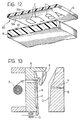
- a multilayer coupled film can be conveniently employed, such as that indicated as 60 in figure 12.
- the film 60 comprises an inner layer 8 of polyethylene admixtured with EVA, and an outer layer 9 of a material which is more resistant to abrasion and also easy to decorate, for instance polyester, polyamide or the like, normally transparent.
- the outer layer 9 may have a lucid outer face 9a, and the inner face 9b thereof i.e. the one which is coupled to the inner layer 9, is decorated by inscriptions 7 or the like.
- the two layers 8 and 9 are coupled therebetween by rolling, with the interposition of and adhesive layer 10, and then the film 60 is applied onto the body 4 of the blade 3 such as clarified in the following, so that the decoration 7 is comprised between the two layers 8 and 9, and thus protected, while at the same time being visible from outside by virtue of the transparency of the outer layer 9.
- a further intermediate layer may additionally be interposed between the two layers 8 and 9, for decoration purposes and in order to enhance the elastic flexional behaviour of the film 60.
- This intermediate layer may be constituted, for instance, by a thin aluminium plate or the like, or by a net of carbon fibres, or anyway by any kind of layer of a material selected so as to modify the flexure performance of the flipper, improving it in terms of power and propulsive efficiency. It is anyhow contemplated within the scope of the present invention that the film layer, be it simple, coupled or multiple, with or without intermediate layers, may be employed to the aim of modifying the flexional behaviour of the blade.
- the film which is adherent to one of the two surfaces (upper or lower) of the blade and which is provided with a module of elasticity different from that of the blade itself, may contribute to appreciably modify section by section the moment of inertia thereof.
- the shrinkage after moulding of the blade may tend to permanently "spoon" deform the blade itself, with consequent effects of mount of the water flow in use, or may impart to the film a permanent tensioning, which in principle will make the flipper more sprung.
- the film 6 (or 60) is applied so as to entirely cover the upper face of the body 4 and the corresponding areas of the two lateral longitudinal members 5.
- the film with the decorations 7 covers only an area, for instance a central band, of the upper face of the body 4.
- the film will be conveniently (and automatically) seated along a corresponding depression 11 of the body 4 (figure 4), whereby its outer face 6b is flush with the upper surface of the body 4, without any thickness rise.
- the film 6 (or 60) shall be unperceived to the touch, further ensuring an efficient adhesion along the time so as to avoid release of the peripheral edges of the film.
- the film 6 (or 60) may be applied onto the lower face of the body 4.
- the film 6 (or 60), instead of being provided with decorations, may simply have a different colour with respect to that of the body 4. It is thus possible to obtain flippers with the upper surface of one colour, and the lower face of a different colour, for aesthetical or event to camouflage purposes.
- the body 4 is covered by the film 6 (or 60) entirely, i.e. both on the upper face and on the lower face thereof.
- the protective effect is complete, and the whole blade 3 may be provided with a pleasant bright aspect, independently of any imperfections of the mould polishing or of localised opacities thereof which might derive from inadequate parameters of the injection moulding.
- the body 4 of the blade 3 which is decorated and/or protected by the film 6 (or 60) may be constituted, instead of the total or partial surface of the blade 3, by an insert pre-moulded in a suitable mould with the respective film, and subsequently placed within the final mould and then embodied in the final flipper moulding.
- the film 6 (or 60) may be applied in the form of separate pieces or sheets onto localised areas of the body 4 of the blade 3.
- the areas of the body 4 of the blade 3 intended to receive this film have no sharp edges or rough changes of thickness, in order to avoid tearing thereof upon application.
- the shape of the body 3 shall be actually designed so that the EVA injection flow has the effect to spread the film 6 (or 60) onto to the mould surface, whereby the film, by virtue of its own flexibility and elasticity, is stretched and laid over the entire mould unevenness.
- the body 4 is formed on its upper face with longitudinal ribs 12, which can be covered by an ultra-elastic film 6 (or 60).
- the fundamental requirements of the selected films consist of flexibility and elasticity, which are peculiar of conventional films of polyethylene admixtured with EVA, readily available on the market. These characteristics are essential not only in connection with application of the film onto the body 4 of the blade 3, so as to copy any surface unevenness of the respective mould, but also in order to follow the flexional deformation which the flipper is subject to in use.
- the monolayer film 6 is certainly more suitable, even if it ensures a lower degree of surface protection of the body 4 and, above all, of the decorations applied thereon.
- the multilayer coupled film 60 is instead preferred due to a more efficient preservation of the decoration and to the better protection thereof.
- the first step consists of the preparation of the film 6 (or 60) with the respective decorations made according to the conventional methods disclosed in the above.
- a conventional injection moulding equipment is employed, constituted, in a generally known way, by a first mould section A and a second mould section B, formed with respective cavities C, D intended to be filled with the thermoplastic material (EVA) for the formation of the body 4 of the blade 3.
- the first mould section A is further provided with a foot body E corresponding to the shape of the shoe 2.
- Reference F diagrammatically indicates a reel for the unwinding of a continuous web of film 6 (or 60) which is guided across the mould A along the area thereof corresponding to the respective cavity C, and to the free end of which a motor-driven gripper-type entrainment and tensioning device, diagrammatically indicated as G, is associated.
- This arrangement enables the automatic positioning, in synchronism with the closing-injection-opening cycle of the injection equipment, of a length of film 6 the size of which is such as to cover the selected application area of the body 4 of the blade 3.
- the positioning of the length of film 6 is such that the decorated outer face 6b of the monolayer film 6 of figure 11, or the outer face 9a of the protective layer 9 of the multilayer film 60 according to figure 12, is placed during the injection phase against the wall of the cavity C of the mould A, i.e. so that the lower face 6a of the monolayer film 6, or that of the inner layer 8 of the multilayer film 60, is facing towards the injection nozzle of the moulding equipment, diagrammatically indicated as H in figure 13.
- the length of film 6 placed in correspondence of the cavity C may be longer or shorter with respect to that of the cavity.
- the edges of the mould section A and of the mould section B shall clamp the film length, following closure therebetween, while in the second case suitable positioning means, not shown but within the knowledge of the man skilled in the art, may be provided.
- thermoplastic material (EVA) intended to generate the body 4 of the blade 5 is injected, and subsequently the thermoplastic rubber for the overmoulding of the shoe is possibly injected.
- the inlet flow of the polymer urges the length of the film 6 (or 60) arranged between the mould section A and the mould section B, against the wall of the cavity C.
- the film is able to copy any possible unevenness of the cavity C which, as previously explained, shall have no sharp edges or excessively rough thickness changes.
- the polymer will be perfectly sticked onto the surface of the film 6 (or 60), since the chemical composition of the latter has an affinity or is identical to that of the polymer which is employed for the body 4 of the blade 3 (EVA) and/or to that possibly employed to form the shoe 2 (elastomeric thermoplastic material admixtured with EVA).
- EVA polymer which is employed for the body 4 of the blade 3
- shoe 2 elastomeric thermoplastic material admixtured with EVA.
- the arrangement shown in figure 13 corresponds to covering of the upper face of the body of the blade 3, for instance according to the configurations depicted in figures 1, 5, 6 and 8. It is evident that the positioning of the film 6 may be varied as a function of the area to be covered: for example, in the case of the configuration according to figure 9, same will be positioned in front of the cavity D of the mould section B.
- the conformation of the article shall be necessarily designed so that the flow of the injected polymer effects stretching of the film 6 (or 60) over the opposite surface of the mould, without producing any negative effect such as crumpling of the film itself.
- the conformation according to figure 8 is considered as the most suitable, since it is able to produce a diverging flow of the injected material and consequent film stretching.
- the film 6 (or 60) shall have to be die-cut in a corresponding size, or more simply the reel F shall have to be narrower or possibly double.
- the preferred embodiment of a central area according to figures 3 and 4 is matching the need that the injection flow does not shift or crumple the film, but instead effects stretching thereof.
- Figure 14 shows another arrangement of the injection equipment, wherein a sheet of film 6 (or 60) already cut in the set size is positioned between the mould section A and the mould section B.
- These film sheets may be drawn from a suitable stock and everytime positioned such as illustrated, for instance with the aid of a vacuum system loader apparatus.
- the film sheet since unlike the case of figure 13 the film sheet can not be maintained in a stretched condition following closure of the injection equipment, it may be useful to arrange the injection nozzle H in the position indicated as H 1 . This avoids any problems of melting or deformation of the sheet of film 6, since the impact of the injected polymer in this case is not direct, by is made indirect via the sole of the foot insert E.
- Figure 15 shows an arrangement for the covering of both faces of the body 4 of the blade 3, with a pair of opposed sheets of film 6 (or 60), or possibly with two lengths of a single folded film web.
- the injection flow in this case shall be conveniently directed to the interspace between the cavities C and D of the mould section A and of the mould section B, respectively, normally through a passage H 2 formed within the foot insert E, so that each sheet of film 6 (or 60) lies down against the wall of the respective cavity.
- FIG 16 diagrammatically shows a body 4 of a blade 3 similar to that of figure 5, following the injection step and before opening between the mould section A and the mould section B.
- the film 6 (or 60) covers the entire upper face of the body 4, copying the configuration of the longitudinal ribs 12, as well as the upper portion of the two lateral longitudinal members 5.
- the free portions of the films 6 (or 60) projecting laterally of the two longitudinal members 5 shall have to be subsequently cut, manually or by means of a suitable powered apparatus within the knowledge of the man skilled in the art.
Landscapes
- Health & Medical Sciences (AREA)
- General Health & Medical Sciences (AREA)
- Physical Education & Sports Medicine (AREA)
- Engineering & Computer Science (AREA)
- Manufacturing & Machinery (AREA)
- Mechanical Engineering (AREA)
- Injection Moulding Of Plastics Or The Like (AREA)
Claims (17)
- Schwimmflosse (1), aufweisend ein biegsames, jedoch relativ steifes Blatt (3) und einen relativ weichen Schuh (2), der mit einem Ende des Blattes (3) verbunden ist, wobei das Blatt (3) einen Körper aus thermoplastischem geformtem Material (4) aufweist, wobei das thermoplastische Material ein Polymer auf Basis von Ethylenvinylazetat ist, und der Körper (4) des Blattes (3) wenigstens teilweise bedeckt ist durch wenigstens eine biegsame und elastische Schicht (6, 60) aus einem thermoplastischen Material, das permanent verbunden ist mit dem Körper (4) durch chemischthermische Adhäsion, dadurch gekennzeichnet, daß die thermoplastische Materialschicht aus einem Film (6, 60) von Polyethylen besteht, dem Ethylenvinylazetat beigemischt ist, wobei die beigemischte Menge des Ethylenvinylazetats zwischen 1 und 30 Gewichtsprozent liegt.
- Flosse nach Anspruch 1, dadurch gekennzeichnet, daß die beigemischte Menge von Ethylenvinylazetat bevorzugt zwischen 2 und 18 Gewichtsprozent liegt.
- Flosse nach Anspruch 1, dadurch gekennzeichnet, daß wenigstens ein Film (6, 60) verbunden ist mit dem Körper (4) des Blattes (3) bei dessen Formung.
- Flosse nach Anspruch 1, dadurch gekennzeichnet, daß der wenigstens eine Film (6) ein Einzelschicht-Film ist.
- Flosse nach Anspruch 4, dadurch gekennzeichnet, daß der Einzelschicht-Film (6) eine unbehandelte Innenfläche (6a) hat zur Verbindung mit dem Körper (4) des Blattes (3), und eine Außenfläche (6b), die behandelt ist, um eine Verzierung (7) aufzunehmen.
- Flosse nach Anspruch 4, dadurch gekennzeichnet, daß der Einzelschicht-Film (6) eine unbehandelte Innenfläche (6a) hat zur Verbindung mit dem Körper (4) des Blattes (3), und eine verzierte Außenfläche (6b).
- Flosse nach Anspruch 1, dadurch gekennzeichnet, daß der wenigstens eine Film ein Vielschicht-gekoppelter Film (60) ist mit einer inneren unbehandelten Schicht (8) zur Verbindung mit dem Körper (4) des Blattes (3), und wenigstens einer äußeren transparenten Schicht (9) mit einer Innenfläche (9b), die mit der Innenschicht (8) verbunden und verziert ist.
- Flosse nach Anspruch 7, dadurch gekennzeichnet, daß eine Mittelschicht zwischengelagert ist zwischen der inneren und äußeren Schicht (8, 9).
- Flosse nach Anspruch 1, wobei der Körper (4) des Blattes (3) eine Oberfläche und eine Unterfläche hat, dadurch gekennzeichnet, daß der wenigstens eine Film (6, 60) die gesamte Oberfläche des Körpers (4) des Blattes (3) abdeckt.
- Flosse nach Anspruch 1, wobei der Körper (4) des Blattes (3) eine Oberfläche und eine Unterfläche hat, dadurch gekennzeichnet, daß der wenigstens eine Film (6, 60) wenigstens teilweise beide Flächen des Körpers (4) des Blattes (3) abdeckt.
- Flosse nach Anspruch 1, wobei der Körper (4) des Blattes (3) wenigstens eine Fläche hat mit einem vertieften mittleren longitudinalen Bereich (11), dadurch gekennzeichnet, daß der wenigstens eine Film (6, 60) den vertieften mittleren longitudinalen Bereich (11) bedeckt, wobei der Film (6, 60) eingebettet ist in dem Körper (4) und mit wenigstens einer Fläche von ihm bündig bzw. fluchtend ist.
- Verfahren zur Herstellung einer Schwimmflosse (1) aufweisend ein biegsames, jedoch relativ steifes Blatt (3) und einen relativ weichen Schuh (2), der mit einem Ende des Blattes verbunden ist, aufweisend die Schritte der Herstellung des Blattes (3) durch Bilden wenigstens eines Körpers (4) aus einem Polymer auf der Basis von Ethylenvinylazetat, das eingespritzt ist in ein Formsystem (A, B), wobei wenigstens ein Film (6, 60) eines thermoplastischen Materials, welches aus Polyethylen, dem eine Menge von Ethylenvinylazetat zwischen 1 und 30 Gewichtsprozent beigemischt ist, besteht, bevorzugt zwischen 2 und 18 Prozent; eingeführt wird in das Formsystem (A, B) vor der Bildung des Körpers (4) und wobei der Film permanent befestigt wird an dem Körper (4) durch chemisch-thermische Adhäsion nach der Einspritzung, um wenigstens partiell den Körper (4) zu bedecken.
- Verfahren nach Anspruch 12, dadurch gekennzeichnet, daß der Einspritzfluß des Ethylenvinylazetats während des Formschritts des Körpers (4) des Blattes (3) dergestalt ausgerichtet ist, daß der wenigstens eine Film (6, 60) gegen eine Fläche (C, D) des Formsystems (A, B) gegenüber der Einspritzdüse (H) liegt.
- Verfahren nach Anspruch 13, dadurch gekennzeichnet, daß der Injektionsfluß des Ethylenvinylazetats während des Formschritts des Körpers (4) des Blattes (3) so ausgerichtet ist, um den wenigstens einen Film (6, 60) gegen die Fläche (C, D) des Formsystems (A, B) auszubreiten und auszudehnen.
- Verfahren nach Anspruch 12, dadurch gekennzeichnet, daß der wenigstens eine Film (6, 60) von einer kontinuierlichen Warenbahntrommel (F) abgezogen wird.
- Verfahren nach Anspruch 12, dadurch gekennzeichnet, daß der wenigstens eine Film (6, 60) eingesetzt ist in das Formsystem (A, B) in der Form von abgestanzten und geformten Blättern, die in der Position gehalten werden vor der Injektion.
- Verfahren nach Anspruch 12, dadurch gekennzeichnet, daß der Körper (4) aus Ethylenvinylazetat, der wenigstens teilweise bedeckt ist durch den wenigstens einen Film (6, 60), als ein Blatteinsatz verwendet wird, der beabsichtigt ist, nachfolgend gestellt zu werden in ein weiteres Formsystem für die Beendigung des Blattes (3).
Applications Claiming Priority (2)
| Application Number | Priority Date | Filing Date | Title |
|---|---|---|---|
| ITTO930562A IT1260671B (it) | 1993-07-28 | 1993-07-28 | Pinna per il nuoto e procedimento per la sua fabbricazione. |
| ITTO930562 | 1993-07-28 |
Publications (2)
| Publication Number | Publication Date |
|---|---|
| EP0640361A1 EP0640361A1 (de) | 1995-03-01 |
| EP0640361B1 true EP0640361B1 (de) | 1997-03-12 |
Family
ID=11411650
Family Applications (1)
| Application Number | Title | Priority Date | Filing Date |
|---|---|---|---|
| EP94830353A Expired - Lifetime EP0640361B1 (de) | 1993-07-28 | 1994-07-13 | Schwimmflosse sowie Verfahren zu ihrer Herstellung |
Country Status (4)
| Country | Link |
|---|---|
| US (1) | US5435764A (de) |
| EP (1) | EP0640361B1 (de) |
| DE (1) | DE69402012T2 (de) |
| IT (1) | IT1260671B (de) |
Cited By (1)
| Publication number | Priority date | Publication date | Assignee | Title |
|---|---|---|---|---|
| WO2004024242A1 (en) * | 2002-09-12 | 2004-03-25 | Pod Ware Pty Ltd | Improvements in swim fins and method of manufacture thereof |
Families Citing this family (27)
| Publication number | Priority date | Publication date | Assignee | Title |
|---|---|---|---|---|
| DE19533234A1 (de) * | 1995-09-08 | 1997-03-13 | Forschungszentrum Mittweida E | Verstärkung des Schwimmflossenblattes |
| US5683279A (en) * | 1995-11-16 | 1997-11-04 | Dacor Corporation | Multi-part diving fin |
| US5746631A (en) * | 1996-01-11 | 1998-05-05 | Mccarthy; Peter T. | High efficiency hydrofoil and swim fin designs |
| US6482059B2 (en) * | 1997-05-09 | 2002-11-19 | Mccarthy Peter T. | High efficiency hydrofoil and swim fin designs |
| US6371821B1 (en) | 1996-01-11 | 2002-04-16 | Nature's Wing Fin Designs, Llc | High efficiency hydrofoil and swim fin designs |
| IT1293218B1 (it) * | 1997-07-11 | 1999-02-16 | Htm Sport Spa | Pala composita in fibro-resina rivestita su entrambi i lati di fogli di materiale termoplastico per pinne per nuoto. |
| IT238455Y1 (it) * | 1997-09-12 | 2000-11-13 | Htm Sport Spa | Pinna per nuoto. |
| US6095879A (en) * | 1998-05-14 | 2000-08-01 | Mccarthy; Peter T. | Methods for creating consistent large scale blade deflections |
| US6843693B2 (en) * | 1998-05-14 | 2005-01-18 | Mccarthy Peter T. | Methods for creating large scale focused blade deflections |
| US6283810B1 (en) * | 1998-11-18 | 2001-09-04 | Robert B. Evans | Non-mold method of forming objects and articles formed thereby |
| US6241567B1 (en) * | 1998-11-18 | 2001-06-05 | Robert B. Evans | Non-mold method of forming objects and articles formed thereby |
| GB2361662B (en) | 2000-04-26 | 2004-08-04 | Matthew James Lewis-Aburn | A method of manufacturing a moulded article and a product of the method |
| ITSV20000045A1 (it) * | 2000-09-29 | 2002-03-29 | Scubapro Europ | Pinna per nuoto ed attivita' subacquee |
| AU2003249321B2 (en) * | 2002-07-19 | 2010-02-18 | Peter T. Mccarthy | Propulsion hydrofoils |
| US7077715B2 (en) | 2002-09-12 | 2006-07-18 | Pod Ware Pty Ltd. | Swim fins and method of manufacture thereof |
| AU2003258381B2 (en) * | 2002-09-12 | 2008-04-17 | Pod Ware Pty Ltd | Improvements in swim fins and method of manufacture thereof |
| ITGE20040032A1 (it) * | 2004-04-28 | 2004-07-28 | H T M Sport S P A | Metodo per il rinforzo delle pale delle pinne per nuoto, e pinne cosi' ottenute. |
| US8168257B2 (en) * | 2006-03-29 | 2012-05-01 | Payless Shoesource Worldwide, Inc. | System and method for printing a pattern on footwear |
| US7854638B2 (en) * | 2008-11-12 | 2010-12-21 | Twombly Susan M | Swim fin device |
| US20110081813A1 (en) * | 2008-11-12 | 2011-04-07 | Twombly Susan M | Recreational Swimming Ensemble |
| US20130005202A1 (en) * | 2011-06-28 | 2013-01-03 | Hsin-Ming Lin | Fin for Swimming, Diving and the Like |
| US9364717B2 (en) * | 2014-01-16 | 2016-06-14 | Kathleen Davis | Swimming fin |
| US9643055B2 (en) | 2015-10-08 | 2017-05-09 | Tyr Sport, Inc. | Swim fin |
| CN106512341A (zh) * | 2016-12-19 | 2017-03-22 | 东莞疆皓塑胶制品有限公司 | 具有装饰结构的蛙鞋 |
| USD886223S1 (en) | 2019-02-08 | 2020-06-02 | Tyr Sport, Inc. | Swim fin |
| US10744374B1 (en) | 2019-04-08 | 2020-08-18 | Tyr Sport, Inc. | Swim fin with an upper portion having debossed regions and triple-bladed rails |
| US10905175B1 (en) | 2020-05-21 | 2021-02-02 | Tyr Sport, Inc. | Swimsuit with tension bands and reinforcement liners |
Family Cites Families (7)
| Publication number | Priority date | Publication date | Assignee | Title |
|---|---|---|---|---|
| US3654062A (en) * | 1970-09-28 | 1972-04-04 | Standard Products Co | Injection molded decorative plaques |
| JPH0195018A (ja) * | 1987-10-07 | 1989-04-13 | Mitsubishi Gas Chem Co Inc | 凹凸面模様入り成形品の製造法 |
| GB8801599D0 (en) * | 1988-01-25 | 1988-02-24 | Du Pont Canada | Process for injection moulding of multi-layered articles |
| IT1242280B (it) * | 1990-01-12 | 1994-03-03 | Technisub Spa | Pinna per il nuoto con pala composita e procedimento per la sua realizzazione |
| JPH0736686Y2 (ja) * | 1992-02-14 | 1995-08-23 | 株式会社タバタ | 遊泳用足ひれ |
| IT1256836B (it) * | 1992-06-03 | 1995-12-21 | Technisub Spa | Pinna per il nuoto. |
| IT1257385B (it) * | 1992-07-17 | 1996-01-15 | Technisub Spa | Pinna per il nuoto. |
-
1993
- 1993-07-28 IT ITTO930562A patent/IT1260671B/it active IP Right Grant
-
1994
- 1994-07-13 EP EP94830353A patent/EP0640361B1/de not_active Expired - Lifetime
- 1994-07-13 DE DE69402012T patent/DE69402012T2/de not_active Expired - Fee Related
- 1994-07-27 US US08/281,185 patent/US5435764A/en not_active Expired - Fee Related
Cited By (1)
| Publication number | Priority date | Publication date | Assignee | Title |
|---|---|---|---|---|
| WO2004024242A1 (en) * | 2002-09-12 | 2004-03-25 | Pod Ware Pty Ltd | Improvements in swim fins and method of manufacture thereof |
Also Published As
| Publication number | Publication date |
|---|---|
| IT1260671B (it) | 1996-04-22 |
| ITTO930562A1 (it) | 1995-01-28 |
| DE69402012T2 (de) | 1997-08-28 |
| EP0640361A1 (de) | 1995-03-01 |
| US5435764A (en) | 1995-07-25 |
| ITTO930562A0 (it) | 1993-07-28 |
| DE69402012D1 (de) | 1997-04-17 |
Similar Documents
| Publication | Publication Date | Title |
|---|---|---|
| EP0640361B1 (de) | Schwimmflosse sowie Verfahren zu ihrer Herstellung | |
| US4877657A (en) | Decorative trim strip with enhanced depth of vision | |
| USRE38246E1 (en) | Segmental face mask | |
| AU624477B2 (en) | Slide fastener | |
| CA2634551C (en) | Methods of making polymeric articles and the polymeric articles formed thereby | |
| US5935692A (en) | Composite for in mold transfer printing | |
| EP1304173B1 (de) | Verfahren zur Herstellung eines Harzformprodukts mit metallisch glänzender Oberfläche | |
| CA2266873A1 (en) | Film finishing system with design option | |
| EP1150587A4 (de) | Verfahren zur herstellung einer spritzgegossenen kofferschale und mit diesem verfahren hergestellter koffer | |
| JPH10329170A (ja) | アクリルインサート成形品とその製造方法、インサート成形用多層フィルム | |
| JP3514565B2 (ja) | インサートフィルムとこれを用いたインサート成形品の製造方法 | |
| KR102100669B1 (ko) | 차량용 내장재의 제조방법 및 차량용 내장재 | |
| CA2034566A1 (en) | Multi-colored one-step sign | |
| JPH01141014A (ja) | ヘアライン表面を有するインモールド成型品の製造方法 | |
| JP3710858B2 (ja) | インサート成形品の製造方法およびインサートフィルム | |
| EP0600187A1 (de) | Verbundschicht zur Verwendung in einem Verfahren zum gleichzeitigen Formen und Transferdrucken beziehungsweise Dekoration von Artikeln aus Kunststoff oder Gummi | |
| JP3500235B2 (ja) | アクリルインサートフィルムとアクリルインサート成形品の製造方法 | |
| KR102005884B1 (ko) | 로고 라벨 제조방법 및 이를 이용한 로고 라벨 | |
| US20220080699A1 (en) | High resolution elastomeric exterior laminate material and method of forming same | |
| JPH1071680A (ja) | アクリル木目模様シート、アクリル木目模様成形品とその製造方法 | |
| JPH081712A (ja) | スエード調の表面を有する成形物及びその製造方法 | |
| US12103274B2 (en) | High resolution elastomeric exterior laminate material and method of forming same | |
| JPH08156218A (ja) | 化粧シ−ト | |
| JPH037227Y2 (de) | ||
| WO2004041498A2 (en) | Multi-shelled appliqué, installation template, and method of trial positioning |
Legal Events
| Date | Code | Title | Description |
|---|---|---|---|
| PUAI | Public reference made under article 153(3) epc to a published international application that has entered the european phase |
Free format text: ORIGINAL CODE: 0009012 |
|
| AK | Designated contracting states |
Kind code of ref document: A1 Designated state(s): CH DE ES FR GB GR IT LI SE |
|
| 17P | Request for examination filed |
Effective date: 19950705 |
|
| GRAG | Despatch of communication of intention to grant |
Free format text: ORIGINAL CODE: EPIDOS AGRA |
|
| 17Q | First examination report despatched |
Effective date: 19960731 |
|
| GRAH | Despatch of communication of intention to grant a patent |
Free format text: ORIGINAL CODE: EPIDOS IGRA |
|
| GRAH | Despatch of communication of intention to grant a patent |
Free format text: ORIGINAL CODE: EPIDOS IGRA |
|
| GRAA | (expected) grant |
Free format text: ORIGINAL CODE: 0009210 |
|
| AK | Designated contracting states |
Kind code of ref document: B1 Designated state(s): CH DE ES FR GB GR IT LI SE |
|
| PG25 | Lapsed in a contracting state [announced via postgrant information from national office to epo] |
Ref country code: LI Effective date: 19970312 Ref country code: IT Free format text: LAPSE BECAUSE OF FAILURE TO SUBMIT A TRANSLATION OF THE DESCRIPTION OR TO PAY THE FEE WITHIN THE PRE;WARNING: LAPSES OF ITALIAN PATENTS WITH EFFECTIVE DATE BEFORE 2007 MAY HAVE OCCURRED AT ANY TIME BEFORE 2007. THE CORRECT EFFECTIVE DATE MAY BE DIFFERENT FROM THE ONE RECORDED.SCRIBED TIME-LIMIT Effective date: 19970312 Ref country code: GR Free format text: LAPSE BECAUSE OF FAILURE TO SUBMIT A TRANSLATION OF THE DESCRIPTION OR TO PAY THE FEE WITHIN THE PRESCRIBED TIME-LIMIT Effective date: 19970312 Ref country code: FR Effective date: 19970312 Ref country code: ES Free format text: THE PATENT HAS BEEN ANNULLED BY A DECISION OF A NATIONAL AUTHORITY Effective date: 19970312 Ref country code: CH Effective date: 19970312 |
|
| REG | Reference to a national code |
Ref country code: CH Ref legal event code: EP |
|
| REF | Corresponds to: |
Ref document number: 69402012 Country of ref document: DE Date of ref document: 19970417 |
|
| PG25 | Lapsed in a contracting state [announced via postgrant information from national office to epo] |
Ref country code: SE Effective date: 19970612 |
|
| EN | Fr: translation not filed | ||
| REG | Reference to a national code |
Ref country code: CH Ref legal event code: PL |
|
| PLBE | No opposition filed within time limit |
Free format text: ORIGINAL CODE: 0009261 |
|
| STAA | Information on the status of an ep patent application or granted ep patent |
Free format text: STATUS: NO OPPOSITION FILED WITHIN TIME LIMIT |
|
| 26N | No opposition filed | ||
| PG25 | Lapsed in a contracting state [announced via postgrant information from national office to epo] |
Ref country code: GB Free format text: LAPSE BECAUSE OF NON-PAYMENT OF DUE FEES Effective date: 19980713 |
|
| GBPC | Gb: european patent ceased through non-payment of renewal fee |
Effective date: 19980713 |
|
| PGFP | Annual fee paid to national office [announced via postgrant information from national office to epo] |
Ref country code: DE Payment date: 20010925 Year of fee payment: 8 |
|
| PG25 | Lapsed in a contracting state [announced via postgrant information from national office to epo] |
Ref country code: DE Free format text: LAPSE BECAUSE OF NON-PAYMENT OF DUE FEES Effective date: 20030201 |