EP0640437A1 - Procédé et appareil pour finir par meulage des pièces métalliques pre usinées de forme anulaire - Google Patents
Procédé et appareil pour finir par meulage des pièces métalliques pre usinées de forme anulaire Download PDFInfo
- Publication number
- EP0640437A1 EP0640437A1 EP94710006A EP94710006A EP0640437A1 EP 0640437 A1 EP0640437 A1 EP 0640437A1 EP 94710006 A EP94710006 A EP 94710006A EP 94710006 A EP94710006 A EP 94710006A EP 0640437 A1 EP0640437 A1 EP 0640437A1
- Authority
- EP
- European Patent Office
- Prior art keywords
- tool
- ring
- grinding
- drive shaft
- spherical cap
- Prior art date
- Legal status (The legal status is an assumption and is not a legal conclusion. Google has not performed a legal analysis and makes no representation as to the accuracy of the status listed.)
- Withdrawn
Links
Images


Classifications
-
- B—PERFORMING OPERATIONS; TRANSPORTING
- B24—GRINDING; POLISHING
- B24B—MACHINES, DEVICES, OR PROCESSES FOR GRINDING OR POLISHING; DRESSING OR CONDITIONING OF ABRADING SURFACES; FEEDING OF GRINDING, POLISHING, OR LAPPING AGENTS
- B24B7/00—Machines or devices designed for grinding plane surfaces on work, including polishing plane glass surfaces; Accessories therefor
- B24B7/10—Single-purpose machines or devices
- B24B7/16—Single-purpose machines or devices for grinding end-faces, e.g. of gauges, rollers, nuts, piston rings
-
- B—PERFORMING OPERATIONS; TRANSPORTING
- B24—GRINDING; POLISHING
- B24B—MACHINES, DEVICES, OR PROCESSES FOR GRINDING OR POLISHING; DRESSING OR CONDITIONING OF ABRADING SURFACES; FEEDING OF GRINDING, POLISHING, OR LAPPING AGENTS
- B24B45/00—Means for securing grinding wheels on rotary arbors
Definitions
- the invention relates to a device for the fine grinding of pre-machined, annular disk-shaped metallic workpieces, in particular of motor vehicle brake disks with an annular disk-shaped brake disk ring and brake disk cup, with a workpiece holder and grinding tool holder, which rotate about axes of their drive shafts that are parallel according to the design specification.
- - Pre-machined workpieces in the form of annular disks refer to those which have their end geometry specified by machining, e.g. B. have experienced on a lathe.
- the cutting shape however, has processing marks on the surface, e.g. B. spiral processing marks. Depending on the requirements placed on the workpieces in the form of annular disks, these interfere from a functional point of view.
- the grinding tool holder as a whole is acted upon by a central helical spring, which presses the ring with the ball-joint-shaped design against the joint ball.
- the joint ball carries two diametrically opposed pins, which are arranged orthogonally to the axis of the drive shaft and are guided in elongated holes of the aforementioned sleeve-shaped hub, so that the grinding tool holder can be pressed back under the influence of the grinding pressure against the action of the coil spring is.
- the ball joint loses its joint function when the grinding tool is working: the sleeve-shaped hub can move in relation to the joint ball, the joint ball can move in an uncontrolled manner in the elongated holes in accordance with the fit of the pins of the joint ball free from the ring with the shape of a spherical joint shell. if only within narrow limits. To this extent, it sits loosely in the sleeve-shaped hub in accordance with the specified tolerances. This often leads to structures similar to chatter marks on the surfaces processed by the grinding process. The formation of these disruptive structures also contributes to the fact that a helical spring is used and that the grinding tool is a grinding wheel which additionally brings about large-area unevenness. As a result, it can be stated that the measures known so far do not meet high quality requirements with regard to the machined workpieces and are in need of improvement.
- the invention is based on the technical problem of developing the device described at the outset with little effort so that the machined workpieces also meet extremely high quality requirements in relation to the machined surfaces.
- the invention is based on the surprising fact that the combination of features a) to d) leads to high surface qualities of the machined workpieces without disruptive structures first produced by the fine grinding process, if the design is such that the workpiece is placed on the ring-shaped workpiece with grinding pressure Ring tool with the annular grindstone on the ring disk-shaped workpiece undergoes a sequence control with deflection around the articulation point of the ball joint formed from the spherical cap and the spherical joint shell.
- gaps must be set up so that the degree of freedom dominated by the ball joint can be used.
- these gap spaces have only a small gap thickness, especially since the inaccuracies that need to be eliminated lie in the ⁇ range.
- the elastic support elements can be arranged under prestress. Their shore hardness is adapted to the special conditions.
- Ring tool with the ring-shaped grindstone on the ring-disk-shaped workpiece undergoes a sequence control, is expressed in that the surface of the ring-disk-shaped workpiece carries out the adjustment and deflection around the ball joint point in accordance with its inaccuracies.
- a positive effect on the accuracy is that the grinding tool is no longer a full-surface grinding wheel, but in a manner known per se is a ring tool with an annular grinding stone, for example a so-called cup wheel.
- the annular grindstone protrudes on the outside over the edge of the ring-shaped workpiece during the grinding process, when this rotating ring tool is placed on the surface of the already rotating workpiece to be ground, a self-sharpening process takes place on the grinding stone itself Device, even with a long operating time, inaccuracies that are based on the fact that the ring tool is working through cannot occur.
- the spherical cap is designed as a hemisphere and molded onto a cylindrical spherical cap carrier.
- the rubber-elastic support elements expediently consist of an annular disk, which surrounds the spherical cap or the spherical cap carrier, and washers on the fastening means of the ring tool on the drive shaft for the tool holder.
- the device shown in the figures is used for the fine grinding of pre-machined, annular disk-shaped metallic workpieces 1, in particular of motor vehicle brake disks with an annular disk-shaped brake disk ring 2 and brake disk cup 3.
- a motor vehicle brake disk 2, 3 is indicated in FIGS. 1 and 4.
- the basic structure of the device includes, among other things, a workpiece holder 4 and a grinding tool holder 5, which rotate about axes of their drive shafts 6 and 7 that are parallel according to the design specification.
- the special design of the grinding tool holder 5 is essential for the invention.
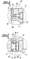
- the grinding tool is a ring tool 8 with an annular grindstone 9, which protrudes on the outside beyond the edge of the ring-shaped workpiece 1 during the grinding process.
- the ring tool 8 has a central spherical joint shell 12 adapted to the spherical cap 11. 2 and 3 it can be seen that between the ring tool 8 and the end face 10 of the drive shaft 6 for the grinding tool holder 5 and, if necessary, the fastening elements 13 for the ring tool 8 rubber-elastic support elements 14 are arranged.
- the arrangement and design is made with the interposition of gap spaces 15, which can also be seen in particular in FIGS. 2 and 3 with an exaggerated gap width, in such a way that the ring tool 8 placed on the ring-shaped workpiece 1 with grinding pressure with the ring-shaped grindstone 9 on it ring-shaped workpiece 1 undergoes a sequence control with deflection around the articulation point 16 of the spherical joint 11, 12 formed from the spherical cap 11 and the spherical joint shell 12.
- the ring tool 8 is designed as a pot tool and the bottom 17 of the pot tool carries the ball joint shell 12.
- the ring tool 8 consists of a tool carrier 18 and the annular grindstone 9 fastened thereon, the tool carrier 18 having the ball joint shell 12 in its base, as it were.
- the spherical cap 11 is designed in the exemplary embodiment as a hemisphere and molded onto a cylindrical spherical cap carrier 19.
- the rubber-elastic support elements consist of a circular washer, which surrounds the spherical cap 11 or the spherical cap carrier 19, and washers 20 on the fastening means 13 of the ring tool 8 on the drive shaft 6 for the grinding tool holder 5.
Landscapes
- Engineering & Computer Science (AREA)
- Mechanical Engineering (AREA)
- Polishing Bodies And Polishing Tools (AREA)
- Grinding Of Cylindrical And Plane Surfaces (AREA)
- Grinding And Polishing Of Tertiary Curved Surfaces And Surfaces With Complex Shapes (AREA)
- Finish Polishing, Edge Sharpening, And Grinding By Specific Grinding Devices (AREA)
- Constituent Portions Of Griding Lathes, Driving, Sensing And Control (AREA)
Applications Claiming Priority (2)
| Application Number | Priority Date | Filing Date | Title |
|---|---|---|---|
| DE4328985A DE4328985C2 (de) | 1993-08-28 | 1993-08-28 | Maschine zum Feinschleifen von vorbearbeiteten, ringscheibenförmigen metallischen Werkstücken |
| DE4328985 | 1993-08-28 |
Publications (1)
| Publication Number | Publication Date |
|---|---|
| EP0640437A1 true EP0640437A1 (fr) | 1995-03-01 |
Family
ID=6496254
Family Applications (1)
| Application Number | Title | Priority Date | Filing Date |
|---|---|---|---|
| EP94710006A Withdrawn EP0640437A1 (fr) | 1993-08-28 | 1994-08-13 | Procédé et appareil pour finir par meulage des pièces métalliques pre usinées de forme anulaire |
Country Status (4)
| Country | Link |
|---|---|
| US (1) | US5472373A (fr) |
| EP (1) | EP0640437A1 (fr) |
| DE (1) | DE4328985C2 (fr) |
| ES (1) | ES2069518T1 (fr) |
Cited By (1)
| Publication number | Priority date | Publication date | Assignee | Title |
|---|---|---|---|---|
| DE19513383A1 (de) * | 1995-04-08 | 1996-10-10 | Supfina Grieshaber Gmbh & Co | Vorrichtung zum beidseitigen Feinstbearbeiten eines Werkstücks |
Families Citing this family (4)
| Publication number | Priority date | Publication date | Assignee | Title |
|---|---|---|---|---|
| FR2795667B1 (fr) * | 1999-07-02 | 2001-10-12 | Essilor Int | Outil de lissage pour surface optique, en particulier pour lentille ophtalmique |
| JP4876669B2 (ja) * | 2006-03-29 | 2012-02-15 | 株式会社ジェイテクト | 車輪用転がり軸受装置の製造方法 |
| GB2521597A (en) * | 2013-11-27 | 2015-07-01 | Aston Martin Lagonda Ltd | Brake conditioning |
| GB201820560D0 (en) | 2018-12-17 | 2019-01-30 | Aston Martin Lagonda Ltd | Assemblies for engines |
Citations (4)
| Publication number | Priority date | Publication date | Assignee | Title |
|---|---|---|---|---|
| US2717478A (en) * | 1952-09-30 | 1955-09-13 | Berne Tocci Guilbert | Grinding machine |
| US3040485A (en) * | 1959-07-16 | 1962-06-26 | Tocci-Guilbert Berne | Resilient coupling |
| DE1239211B (de) * | 1964-10-14 | 1967-04-20 | Wilhelm Lot K G Optikmaschinen | Kardanisch gelagertes Optik-Schleif- oder Polierwerkzeug |
| US3473269A (en) * | 1967-05-05 | 1969-10-21 | La Salle Machine Tool | Grinding apparatus |
Family Cites Families (16)
| Publication number | Priority date | Publication date | Assignee | Title |
|---|---|---|---|---|
| US2716312A (en) * | 1953-03-09 | 1955-08-30 | Elmer W Speicher | Truing device for face-type diamond abrasive wheels |
| DE1695256U (de) * | 1954-11-02 | 1955-03-24 | Bergin G M B H | Anordnung zur befestigung von schleifscheiben an schleifmaschinen. |
| US2883805A (en) * | 1958-02-24 | 1959-04-28 | Pittsburgh Plate Glass Co | Polisher block swivel joint |
| US2918760A (en) * | 1958-02-26 | 1959-12-29 | Flexan Corp | Abrading disk mount |
| US3053063A (en) * | 1960-08-03 | 1962-09-11 | Flexan Corp | Abrading disc mount |
| US3456401A (en) * | 1965-08-30 | 1969-07-22 | Ammco Tools Inc | Brake disc grinder |
| US3500589A (en) * | 1967-07-25 | 1970-03-17 | Fmc Corp | Disc brake grinder |
| ZA755807B (en) * | 1975-09-11 | 1977-04-27 | Edenvale Eng Works | The mounting of grinding wheels |
| JPS5537289A (en) * | 1978-06-29 | 1980-03-15 | Gramlich Hans | Reepolishing method of brake disc for car and its polishing device |
| US4766702A (en) * | 1985-07-25 | 1988-08-30 | James Kinner | Disk brake grinder |
| DE3642304C1 (de) * | 1986-12-11 | 1988-01-21 | Supfina Maschf Hentzen | Verfahren zum Schleifen planparalleler Kreisringflaechen an scheibenfoermigen Werkstuecken |
| US4825596A (en) * | 1986-12-18 | 1989-05-02 | James Kinner | Flywheel resurfacing method and apparatus |
| DE3911719A1 (de) * | 1989-04-11 | 1990-10-25 | Thielenhaus Maschf | Anlage zum schleifen, insbesondere feinschleifen, von bremsscheiben |
| DE3914720A1 (de) * | 1989-05-04 | 1990-11-08 | Thielenhaus Maschf | Schleifmaschine, insbes. feinschleifmaschine, fuer das schleifen von kraftfahrzeugbremsscheiben |
| US5056266A (en) * | 1990-01-04 | 1991-10-15 | Norris Bobby D | Rotary brake rotor resurfacer |
| US5381630A (en) * | 1992-09-28 | 1995-01-17 | Kinner; James | Brake rotor grinding method and apparatus |
-
1993
- 1993-08-28 DE DE4328985A patent/DE4328985C2/de not_active Expired - Fee Related
-
1994
- 1994-08-13 EP EP94710006A patent/EP0640437A1/fr not_active Withdrawn
- 1994-08-13 ES ES94710006T patent/ES2069518T1/es active Pending
- 1994-08-15 US US08/291,583 patent/US5472373A/en not_active Expired - Fee Related
Patent Citations (4)
| Publication number | Priority date | Publication date | Assignee | Title |
|---|---|---|---|---|
| US2717478A (en) * | 1952-09-30 | 1955-09-13 | Berne Tocci Guilbert | Grinding machine |
| US3040485A (en) * | 1959-07-16 | 1962-06-26 | Tocci-Guilbert Berne | Resilient coupling |
| DE1239211B (de) * | 1964-10-14 | 1967-04-20 | Wilhelm Lot K G Optikmaschinen | Kardanisch gelagertes Optik-Schleif- oder Polierwerkzeug |
| US3473269A (en) * | 1967-05-05 | 1969-10-21 | La Salle Machine Tool | Grinding apparatus |
Cited By (1)
| Publication number | Priority date | Publication date | Assignee | Title |
|---|---|---|---|---|
| DE19513383A1 (de) * | 1995-04-08 | 1996-10-10 | Supfina Grieshaber Gmbh & Co | Vorrichtung zum beidseitigen Feinstbearbeiten eines Werkstücks |
Also Published As
| Publication number | Publication date |
|---|---|
| DE4328985A1 (de) | 1995-03-02 |
| ES2069518T1 (es) | 1995-05-16 |
| US5472373A (en) | 1995-12-05 |
| DE4328985C2 (de) | 1995-12-07 |
Similar Documents
| Publication | Publication Date | Title |
|---|---|---|
| EP0807491A1 (fr) | Support pour lentille optique et procédé pour polir des lentilles | |
| DE4328987C1 (de) | Verwendung einer Schleifvorrichtung zum Feinschleifen von Kraftfahrzeugbremsen | |
| EP0640437A1 (fr) | Procédé et appareil pour finir par meulage des pièces métalliques pre usinées de forme anulaire | |
| DE60206518T2 (de) | Werkzeughaltevorrichtung für hochgenaue kalibrierung von löchern | |
| EP0803325A2 (fr) | Procédé pour le meulage façonné du bord de circonférence de verres de lunettes et le cas échéant meulage de facette suivant ainsi que dispositif de meulage pour les bords de verres de lunettes | |
| CH685544A5 (de) | Verfahren zum Umfangs- und Fasenschleifen von Schneidplatten und Vorrichtung zur Durchführung des Verfahrens. | |
| DE3875143T2 (de) | Vorrichtung zum polieren. | |
| DE112004001774T5 (de) | Abrichtverfahren für eine vertikale Doppelkopf-Flächenschleifmaschine | |
| DE4208615C1 (en) | Grinding spindle with concentric pot-shaped sliding discs - has inner disc protrusions extending radially between axial protrusions on outer disc | |
| DE1918347A1 (de) | Steuergeraet zum Schleifen eines Einkristalls | |
| EP0374550B1 (fr) | Dispositif additionnel, par exemple pour une fraiseuse | |
| EP0322578A2 (fr) | Dispositif de centrage de lentilles optiques pour le montage mécanique, en particulier lors du meulage des bords et de facettes | |
| WO2021013779A1 (fr) | Dispositif de traitement de bords de pièces à usiner planes | |
| DE9320770U1 (de) | Vorrichtung zum Feinschleifen von vorbearbeiteten, ringscheibenförmigen metallischen Werkstücken | |
| DE29922974U1 (de) | Schleifmaschine | |
| AT526662B1 (de) | Vorrichtung zum Bearbeiten von Rändern von flächigen Werkstücken | |
| DE8916001U1 (de) | Vorrichtung zur materialabhebenden Fein- oder Feinstbearbeitung | |
| DE2407261C3 (de) | Vorrichtung für die schleifende Bearbeitung der ebenen Stirnfläche an einem im übrigen hohlzylindrischen Werkstück | |
| CH673802A5 (fr) | ||
| DE620546C (de) | Mitnehmer fuer Werkstuecke, die zwischen Spitzen, vorzugsweise auf Drehbaenken, bearbeitet werden | |
| DE102017103576A1 (de) | Schleifmaschine zum Rundschleifen von Werkstücken | |
| DD227073A1 (de) | Verfahren zur erzeugung von kugelfoermigen oberflaechen auf koordinatenschleifmaschinen | |
| DE8100044U1 (de) | "kombiniertes fraes- und schleifwerkzeug" | |
| EP0316451A1 (fr) | Dispositif d'usinage abrasif | |
| WO1997043088A1 (fr) | Dispositif pour rectifier des vilebrequins ou pieces similaires |
Legal Events
| Date | Code | Title | Description |
|---|---|---|---|
| PUAI | Public reference made under article 153(3) epc to a published international application that has entered the european phase |
Free format text: ORIGINAL CODE: 0009012 |
|
| AK | Designated contracting states |
Kind code of ref document: A1 Designated state(s): CH DE ES FR GB IT LI |
|
| 17P | Request for examination filed |
Effective date: 19950106 |
|
| ITCL | It: translation for ep claims filed |
Representative=s name: ING. A. GIAMBROCONO & C. S.R.L. |
|
| EL | Fr: translation of claims filed | ||
| REG | Reference to a national code |
Ref country code: ES Ref legal event code: BA2A Ref document number: 2069518 Country of ref document: ES Kind code of ref document: T1 |
|
| GBC | Gb: translation of claims filed (gb section 78(7)/1977) | ||
| 17Q | First examination report despatched |
Effective date: 19950816 |
|
| GRAG | Despatch of communication of intention to grant |
Free format text: ORIGINAL CODE: EPIDOS AGRA |
|
| GRAH | Despatch of communication of intention to grant a patent |
Free format text: ORIGINAL CODE: EPIDOS IGRA |
|
| STAA | Information on the status of an ep patent application or granted ep patent |
Free format text: STATUS: THE APPLICATION HAS BEEN WITHDRAWN |
|
| 18W | Application withdrawn |
Withdrawal date: 19960808 |