EP0642003A1 - Dispositif et méthode combinatoire de pesage ou de comptage - Google Patents
Dispositif et méthode combinatoire de pesage ou de comptage Download PDFInfo
- Publication number
- EP0642003A1 EP0642003A1 EP94306609A EP94306609A EP0642003A1 EP 0642003 A1 EP0642003 A1 EP 0642003A1 EP 94306609 A EP94306609 A EP 94306609A EP 94306609 A EP94306609 A EP 94306609A EP 0642003 A1 EP0642003 A1 EP 0642003A1
- Authority
- EP
- European Patent Office
- Prior art keywords
- weighing
- target supply
- value
- articles
- weighing hoppers
- Prior art date
- Legal status (The legal status is an assumption and is not a legal conclusion. Google has not performed a legal analysis and makes no representation as to the accuracy of the status listed.)
- Granted
Links
Images


Classifications
-
- G—PHYSICS
- G01—MEASURING; TESTING
- G01G—WEIGHING
- G01G19/00—Weighing apparatus or methods adapted for special purposes not provided for in the preceding groups
- G01G19/40—Weighing apparatus or methods adapted for special purposes not provided for in the preceding groups with provisions for indicating, recording, or computing price or other quantities dependent on the weight
- G01G19/42—Weighing apparatus or methods adapted for special purposes not provided for in the preceding groups with provisions for indicating, recording, or computing price or other quantities dependent on the weight for counting by weighing
-
- G—PHYSICS
- G01—MEASURING; TESTING
- G01G—WEIGHING
- G01G19/00—Weighing apparatus or methods adapted for special purposes not provided for in the preceding groups
- G01G19/387—Weighing apparatus or methods adapted for special purposes not provided for in the preceding groups for combinatorial weighing, i.e. selecting a combination of articles whose total weight or number is closest to a desired value
- G01G19/393—Weighing apparatus or methods adapted for special purposes not provided for in the preceding groups for combinatorial weighing, i.e. selecting a combination of articles whose total weight or number is closest to a desired value using two or more weighing units
Definitions
- the present invention relates to a combinational weighing or counting method and an apparatus therefor which utilize a plurality of weighing devices for weighing or counting a plurality of articles of varying value such as, for example, snacks, candies, fruits, vegetables or precise machine parts, and then to select an appropriate combination of the articles based on results of weight measurements or counts.
- a combinational weighing apparatus is well known and is disclosed in, for example, the Japanese Laid-open Patent Publication No. 63-30725 published in 1988.
- the combinational weighing apparatus is a machine utilizing a plurality of weighing hoppers operatively coupled with a packaging machine so that bags each containing a plurality of articles, such as, for example, snacks, candies, fruits or vegetables, of varying value, can be averaged or substantially matched in value to a target combined value by selecting a combination of weighing hoppers accommodating the respective articles, the total value of which would meet with the target combined value for the bag.
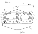
- articles M to be weighed which have been transported by means of a delivery conveyor 1 are dispensed through a dispensing feeder 2 into a plurality of driving or article-conducting feeders 31 to 3 n which subsequently loads fractions of the articles into respective weighing hoppers 61 to 6 n .
- a combination control means (not shown) selects some of the weighing hoppers 61 to 6 n to thereby select an appropriate combination of the weighing hoppers 61 to 6 n .
- the combination control means selects the appropriate combination of the weighing hoppers 61 to 6 n which would eventually provide a bag of the articles having a total value equal or generally equal to a target combined value.
- the respective fractions of the articles M accommodated within the weighing hoppers 61 to 6 n of the selected combination are discharged into a collecting chute 9 for loading to a bag or any other receptacle.
- the amount of the articles M to be supplied into each of the weighing hoppers 61 to 6 n is equal or approximate to a predetermined supply value T (for example, the quotient of the target combined value T M divided by the number m of the weighing hoppers selected for the optimum combination) to which the articles are supplied into the respective weighing hoppers 61 to 6 n .
- a predetermined supply value T for example, the quotient of the target combined value T M divided by the number m of the weighing hoppers selected for the optimum combination
- parameters for controlling a supply ability of each of the driving feeders 31 to 3 n are controlled in the following manner.
- a parameter setting means determines, for each of the driving feeders 31 to 3 n , parameters for the current weighing cycle on the basis of the parameters for the previous weighing cycle and the amounts of the articles actually supplied into the weighing hoppers 61 to 6 n during the previous weighing cycle.
- the driving feeders 31 to 3 n are vibrated according to the parameter so determined for the current weighing cycle that the amounts of the articles M corresponding to the predetermined supply value T can be supplied into the respective weighing hoppers 61 to 6 n .
- the value of the articles actually supplied into each weighing hopper 61 to 6 n does unavoidably take a value somewhat differing from the predetermined supply value T. Because of this, the measured value W1 to W n of the articles M accommodated in each of the weighing hoppers 61 to 6 n may often become short of the predetermined supply value T to which the articles should be supplied into the respective weighing hopper 61 to 6 n as shown in Fig. 15. In such case, the combined value W M corresponding to a combination of measured values W i of m articles expected for the value measurement becomes slightly smaller than the target combined value T M . On the other hand, the combined value W M obtained by summing a combination of the measured values Wi given by the selected combination of m + 1 weighing hoppers exceeds considerably over the target combined value T M .
- a combinational weighing or counting method comprises the steps of: driving a plurality of driving feeders for supplying articles from an upstream side into a plurality of weighing hoppers according to a predetermined parameter for controlling a supply ability of the driving feeder; determining a new parameter for each of the driving feeders on the basis of a target supply value for each weighing hopper, to which the respective weighing hopper is supplied with the articles, and a measured weight of the articles supplied into each weighing hopper; and selecting a combination of the articles on the basis of the measured values and a target combined value, some or all of the target supply values for the respective weighing hoppers being chosen to be different from each other.
- a combinational weighing or counting apparatus comprises a plurality of weighing hoppers; a plurality of driving feeders for supplying articles from an upstream side towards the corresponding weighing hoppers; a feeder drive control for driving the driving feeders for supplying articles to the weighing hoppers according to a predetermined parameter; a parameter setting means for setting a new parameter for each of the driving feeders on the basis of a target supply value for each weighing hopper to which the respective weighing hopper is supplied with the articles, and a measured weight of the articles supplied into each weighing hopper; a combination control means for selecting a combination of the measured weights of the articles supplied into the weighing hoppers which combination has a value equal to a target combined value or within an allowance thereof; and a target supply value calculating means for setting some or all of the target supply values for the respective weighing hoppers to be of values different from each other.
- a combinational weighing or counting apparatus comprises a plurality of weighing hoppers; a plurality of driving feeders for supplying articles from an upstream side towards the corresponding weighing hoppers; a feeder drive control for driving the driving feeders for supplying articles to the weighing hoppers according to a predetermined parameter; a parameter setting means for setting a new parameter for each of the driving feeders on the basis of a target supply value for each weighing hopper, to which the respective weighing hopper is supplied with the articles, and a measured weight of the articles supplied into each weighing hopper; a combination control means for selecting a combination of the measured weight of the articles supplied into the weighing hoppers which combination has a value equal to a target combined value or within an allowance thereof; and a target supply value storage means for storing the target supply value for each weighing hopper.
- the use is made of some or all of the target supply values for the respective weighing hoppers which are different from each other. Accordingly, actual amounts of supply of the articles to the respective weighing hoppers can take different values and combinational calculation of those actual amounts which are combined results in various values. Consequently, results of the combinational calculation approximating to the target combined value can be obtained.
- the various combinational calculated weights W M can be obtained and, therefore, it is preferred that the target supply values T1 to T n differ from each other to some extent.
- the difference between the target supply values T1 to T n is excessively large, the actual amount of supply of the articles into some of the weighing hoppers which have a relatively small target supply value will become zero, that is, empty weighing hoppers will occur, resulting in undesirable reduction in number of the weighing hoppers that can be selected for the combination.
- the combinational weighing or counting apparatus comprises, in addition to the target supply value calculating means for setting some or all of the target supply values for the corresponding weighing hoppers to be of respective values different from each other, a target supply value control means for controlling the target supply value calculating means on the basis of the measured weights of the articles in the weighing hoppers so as to minimize the probability that the weight of the articles subsequently supplied into the respective weighing hopper may become zero.
- a target supply value control means for controlling the target supply value calculating means on the basis of the measured weights of the articles in the weighing hoppers so as to minimize the probability that the weight of the articles subsequently supplied into the respective weighing hopper may become zero.
- the combinational weighing or counting apparatus is provided with a target supply value storage means for storing the target supply value for each weighing hopper, and a target supply value calculating means for calculating the target supply value for each weighing hopper on the basis of the target combined value or the average value of the target supply values for all weighing hoppers and for outputting the calculated target supply value to the target supply value storage means for storage thereof in such target supply value storage means.
- the target supply value calculating means calculates the target supply value for each weighing hopper on the basis of the target combined value or the average value of the target supply values and, therefore, an operator of the apparatus need not calculate and input the target supply value for each weighing hopper. Therefore, the apparatus is easy to operate and there is no possibility of an error occuring during the inputting.
- the measured weights associated with the respective weighing hoppers may deviate relative to the target supply values. If this deviation is small, it may occur that the measured weights will coordinate at a small value. To avoid this possibility, it is necessary to render the difference between the target supply values for the corresponding weighing hoppers to be great.
- the deviation referred to above is greater than a predetermined value the difference between the target supply values for the corresponding weighing hoppers is made large, some of the weighing hoppers will be supplied with the articles in an excessively great or smaller quantity (in terms of the measured weight) and such weighing hoppers will no longer be utilized for selection of the combination and, in such case, the number of combinations will decrease substantially. Accordingly, where the deviation referred to above is greater than the predetermined value, it is necessary to decrease the difference between the target supply values for the corresponding weighing hoppers.
- the combinational weighing or counting apparatus is provided with, in addition to the target supply value storage means, a target supply value calculating means for calculating the target supply value for each weighing hopper and for storing the calculated target supply value in the target supply value storage means; a deviation calculating means for calculating a degree of deviation in measured weight of each weighing hopper on the basis of the measured weights of the articles which have previously been supplied into the weighing hoppers during previous weighing cycles; and a target supply value control means for controlling the target value calculating means on the basis of the degree of deviation.
- a deviation may occur in the target supply value to such an extent that, statistically, no measured weight closer to the target supply value can be obtained.
- the combinational weighing or counting apparatus has the weighing hoppers divided into a first group of the weighing hoppers having a relatively great target supply value and a second group of weighing hoppers having a relatively small target supply values, said first and second groups of the weighing hoppers being disposed around a periphery of a circular dispensing feeder, and is provided with a delivery conveyor supplying by gravity the articles to the dispensing feeder so that the articles are supplied into the first group of the weighing hoppers in a quantity greater than those supplied into the second group of the weighing hoppers.
- the calculated weights in which an arbitrarily chosen number m of the measured weights W1 to W n are combined and the combinational calculated weight in which a number (m + 1) of the measured weights W1 to W n are combined may take scattering values, respectively, and therefore, it is necessary to render the measured weight to have a deviation.
- the combinational weighing or counting apparatus is provided with an average measured weight calculating means, a standard parameter setting means and a deviated parameter calculating means.
- the average measured weight calculating means is operable to calculate, for each of the weighing hoppers, an average value of the measured weights of the articles which have previously been supplied into the weighing hoppers during previous weighing cycles.
- the standard parameter setting means is operable to determine a standard parameter, which may be used as a reference for a new parameter, on the basis of excess or shortage of the amount of supply of the articles determined as a result of comparison between the average measured value and the target supply value.
- the deviated parameter calculating means is operable to calculate, for each of the weighing hoppers, a new parameter having a deviation in reference to the standard parameter.
- the driving feeders can be driven by calculating the new reference parameter based on the average measured weight calculated on the basis of the previously measured weights of the articles supplied into the respective weighing hoppers during the previous weighing cycles and the target supply value and by applying a deviation to the reference parameter. Therefore, the deviation can be given to the measured weight for each of the weighing hopper, giving rise to a result of combination which further approximates to the target supply value.
- the measured weights W i may take a varying value relative to the target supply value T, if the deviation of the measured weights W i is smaller than a predetennined value to a certain extent, a case may occur in which both of the combinational calculated weight in which an arbitrarily chosen number m of the measured weights W1 to W n shown in Fig. 15 are combined and the combinational calculated weight in which a number (m + 1) of the measured weights W1 to W n are combined may take a scattering value, and therefore, it is necessary to impart a deviation to the measured weights W i .
- the present invention provides the combinational weighing or counting apparatus which is provided with all average measured value calculating means, a standard parameter setting means, a deviation determining means and a deviated parameter calculating means.
- the average measured value calculating means is operable to calculate, for each of the weighing hoppers, an average value of the measured weights of the articles which have previously been supplied into the weighing hoppers during previous weighing cycles.
- the standard parameter setting means is operable to detennine a standard parameter, which may be used as a reference for a new parameter, on the basis of excess or shortage of the amount of supply of the articles determined as a result of comparison between the average measured value and the target supply value.
- the deviation determining means operates to determine, on the basis of the measured weights of the articles which have previously been supplied into the weighing hoppers during previous weighing cycles, excess or shortage of a degree of deviation of each of the measured weight.
- the deviated parameter calculating means calculates, for each of the weighing hoppers, a new parameter on the basis of the standard parameter and the excess or shortage of the degree of deviation.
- the respective target supply values T for the weighing hoppers may be equal to each other in this case.
- Figs. 1 to 5 illustrates a first preferred embodiment of the present invention.
- a delivery conveyor 1 is operable to fall articles M to be weighed onto a central portion of a generally flat conical distributing feeder 2.
- a number n of driving or article-conducting feeders 31 to 3 n are disposed around and substantially beneath an outer peripheral edge of the distributing feeder 2.
- Each of these driving feeders 31 to 3 n is, while driven according to predetermined parameters, that is, while vibrated at a predetermined amplitude for a predetermined length of time, operable to feed the articles M to be weighed on the distributing feeder 2 onto an equal number n of pooling hoppers 41 to 4 n each provided with a respective gate 51 to 5 n .
- Weighing hoppers 61 to 6 n are disposed immediately beneath the associated pooling hoppers 41 to 4 n .
- Each of the weighing hoppers 61 to 6 n is provided with a respective hopper weight measuring device 71 to 7 n and a respective gate 81 to 8 n .
- a relatively large-sized discharge chute 9 Positioned beneath the gates 81 to 8 n are a relatively large-sized discharge chute 9.
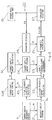
- each of the hopper weight measuring devices 7 i comprises, for example, a load cell and is operable to measure the weight of the articles M within the corresponding weighing hopper 6 i (Fig. 2) and also to output the measured weight W i to a combination control means 10 and a parameter setting means 20.
- a suffix "i" affixed to some of the reference numerals is intended to means that the element or signal designated by the relevant reference numeral to which the suffix is affixed is employed in a plural number n.
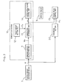
- both of the combination control means 10 and the parameter setting means 20 are comprised of a microcomputer (CPU).
- the combination control means 10 is operable to select an appropriate combination of the weighing hoppers 6 i by combining some of the weights of the articles M measured respectively by the weighing hoppers 61 to 6 n shown in Fig. 2.
- the combination control means 10 shown in Fig. 2 comprises a combined weight calculating unit 11, a target weight setting unit 12, a combination determining unit 13 and a hopper oper/close control unit 14.
- the combined weight calculating unit 11 performs a summation of a combination of arbitrarily chosen m measured weights W i out from the measured weights W1 to W n measured respectively by the hopper weight measuring devices 71 to 7 n and then outputs the summed weight W M , that is, the total weight of the number m of the measured weights W i to the combination determining unit 13. This summation and the outputting of the summed weight W M are carried out subject to all combinations.
- the combination determining unit 13 compares the summed weight W M from the combined weight calculating unit 11 with a target combined value T M fed from the target weight setting unit 12 to select the weight of the articles M which is equal to the target combined value T M or within an allowance between a lower limit value (normally, equal to the target combined value T M ) and an upper limit value, and then outputs a selection signal a to the hopper open/close control unit 14 and a feeder control unit 15 i .
- the hopper open/close control unit 14 opens the gates 8 i of a selected number m of the weighing hoppers 6 i . In this way, the articles M are discharged from the selected weighing hoppers 6 i , subsequently collected together in the collecting and discharge chute 9 and finally supplied onto a packaging machine 9A. Also, the hopper open/close control units 14 (Fig. 3) opens the gates 5 i of some of the pool hoppers 4 i which are associated with the emptied weighing hoppers 6 i , thereby allowing the articles M to be supplied from such pool hopper 4 i onto such weighing hoppers 6 i .
- the feeder drive control unit 15 i is employed for each of the drive feeders 3 i and is operable to drive the drive feeders 3 i associated with the emptied pooling hoppers 4 i shown in Fig. 2 according to the predetermined parameter to deliver the articles M to the pool hoppers 41.
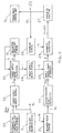
- the parameter setting means 20 comprises various means shown by the sold lines.
- Each measured weight storage means 21 i receives the measured weight W i from the associated hopper weight measuring device 7 i and stores a number of the measured weights W i1 to W iN which have previously been measured during a number N of measuring cycles.
- each measured weight storage means 21 i stores, as shown in Fig. 5(b), the measured weights W i1 to W iN measured by the associated hopper weight measuring device 7 i during the first to N-th measuring cycles.
- the measured weights W i1 to W iN stored in each measured weight storage means 21 i are supplied to an average measured weight calculating means 22 i by which, according to the following equation (2) and as shown in Fig. 5(c), an average value W ia of the weights measured by the i-th hopper weight measuring device 7 i is obtained.
- W ia (W i1 + W i2 + ⁇ + W ij + ⁇ + W iN )/N wherein W ij represents the measured weight measured by the i-th hopper weight measuring device 7 i during the measuring cycle preceding j times and N represents a natural integer selected within the range of, for example, 1 to 20.
- the average measured weight calculating means 22 i outputs the average measured weight W ia to a supply excess/short determining means 23 i shown in Fig. 9.
- This supply short/excess determining means 23 i compares the average measured weight W ia with a target supply value T i for each weighing hopper 6 i (Fig. 2) which is stored in a target supply value storage means 24 and then outputs an excess/short signal b to a parameter calculating means 25 i .
- the target supply value T i will be described in detail later.
- each parameter calculating means 25 i calculates a new parameter P i + ⁇ P i .
- the parameter calculating means 25 calculates the new parameter P i + ⁇ P i by subtracting a single unit from the parameter P i for the previous weighing cycle in the event that the average measured weight W ia is greater than the target supply value T i (in this case, ⁇ P i takes a negative value), but calculates the new parameter P i + ⁇ P i by adding a single unit to the parameter P i for the previous weighing cycle in the event that the average measured weight W ia is smaller than the target supply value T i (in this case, ⁇ P i takes a positive value).
- the new parameter P i + ⁇ P i is outputted from the parameter calculating means 25 i to a parameter adjusting means 27.
- This parameter adjusting means 27 determines whether or not the new parameter P i + ⁇ P i is proper in the light of the balance between the weighing hopper 61 to 6 n and, in the event that the parameter P i + ⁇ P i is found not proper, modifies it to provide a parameter P1 i for the next succeeding weighing cycle.
- the parameter adjusting means 27 referred to above stores a predetermined balance control value ⁇ and is, therefore, operable to adjust the parameter P1 i for the next succeeding weighing cycle to a value greater than the lowermost limit value (Pa - ⁇ ) and smaller than the uppermost limit value (Pa + ⁇ ).
- Pa referred to above represents a calculated average value (a simple average value) of the new parameters (P1 + ⁇ P1) to (P n + ⁇ P n ).
- the parameter P1 i for the next succeeding weighing cycle is outputted to both of a feeder drive control device 15 i and the parameter storage means 26 i .
- Each feeder drive control unit 15 i is operable to control the length of time during which the associated driving feeder 3 i (Fig. 2) is to be vibrated, which time is hereinafter referred to as the vibrating time, and the amplitude of vibration according to the parameter P1 i for the next succeeding weighing cycle.
- the parameter storage means 26 i stores the parameter P1 i for the next succeeding weighing cycle as the parameter P i for the previous weighing cycle so that the latter can be used for the determination of the parameter P1 i for a further next succeeding weighing cycle.
- the target supply value storage means 24 stores target supply values T1 to T n for the associated weighing hoppers 61 to 6 n shown in Fig. 2.
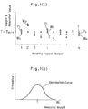
- All of the target supply values T i to T n stored in the previously discussed target supply value storage means 24 are set to respective values different from each other as shown in Fig.5(a).
- Each of these target supply values T i is calculated by a target supply value calculating means 30 according to the following equation (3), and the target supply value calculating means 30 supplies the respective target supply value T i , so calculated thereby, to the target supply value storage means 24 to update the contents stored in such target supply value storage means 24.
- T i (T M /m) + A ⁇ [i - ⁇ (n + 1)/2 ⁇ ]
- A represents a coefficient of inclination
- T M represents a target combined value
- n represents the total number of the hoppers.
- each target supply value T i is defined as a linear function of i as shown in, for example, Fig. 1(a). It is to be noted that, in the foregoing equation (3), the target combined value T M , the number m and the total number n of the hoppers are determined beforehand.
- the target supply values T i to T n calculated according to the foregoing equation (3) take respective values T i to Tn different from each other, and the target supply value T i+1 and T i-1 which are greater and smaller, respectively, than the target supply value T i for the arbitrarily chosen weighing hopper 6 i and closest to the target supply value T i satisfy the following equation (1).
- T i+1 - T i T i - T i-1
- the difference among the target supply values for the weighing hoppers 6 i is constant and, accordingly, all of the target supply values T1 to T n vary linearly. In the practice of the present invention, however, the difference referred to above may not be always constant and the target supply values T1 to T n may accordingly vary so as to depict a curve.
- the coefficient of inclination A is a parameter to be updated by the target supply value calculating means 30 each time the combination weighing is to be performed, and is updated and stored in an inclination coefficient storage means 31 for each weighing cycle.
- the target supply value calculating means 30 is controlled by a target supply value control means 32 in the manner which will now be described.
- the target supply value control means 32 is inputted with both of the measured weight W1, given by one of the hopper weight measuring devices 71 to 7 n that is associated with the weighing hopper 61 for which the target supply value is minimum, and the measured weight W n given by another one of the hopper weight measuring devices 71 to 7 n that is associated with the weighing hopper 6 n for which the target supply value is maximum, and is also inputted with the lowermost limit value W MIN and the uppermost limit value W MAX from a uppermost and lowermost limit value storage means 33.
- the target supply value control means 32 also compares the maximum measured weight W n with the uppermost limit value W MAX and outputs a control command c necessary to reduce the coefficient A of inclination to the target supply value calculating means 30 in the event that the measured weight W1 is greater than the uppermost limit value W MAX .
- a counter not shown starts counting.
- the target supply value control means 32 outputs a control command c necessary to increase the coefficient A of inclination to the target supply value calculating means 30.
- the target supply value control means 32 minimizes the probability that the weight of the articles M to be dispensed into each weighing hopper 6 i becomes zero or excessive. It is, however, to be noted that, in the event that the average value of the target supply values T i is, for example, 20 grams, the lowermost limit value W MIN is set to about 10 grains and the uppermost limit value W MAX is set to about 30 grams.
- the articles M to be weighed are supplied from the delivery conveyor 1 shown in Fig. 2 to a position above the distributing feeder 2 and are, after having been passed through the driving feeder 3 i , the pooling hopper 4 i , the weighing hopper 6 i and the collecting and discharge chute 9, collected and packaged by the packaging machine 9A.
- the combination control means 10 shown in Fig. 3 selects a combination of an appropriate number m of the weighing hoppers 6 i (Fig. 2) as hereinbefore described. Subsequently, the combination control means 10 selects a combination of the remaining weighing hoppers 6 i and, similarly, a combinational discharge is carried out.
- the hopper open/close control unit 14 opens the gates 5 i of the pooling hoppers 41 associated with the weighing hoppers 6 i as shown in Fig. 2 from which the articles M have been discharged, to allow the articles M to be delivered from the pooling hoppers 4 i to the empty weighing hoppers 6 i . Also, the driving feeders 3 i associated with the pooling hoppers 4 i from which the articles M have been discharged are driven to supply the articles M onto the empty pooling hopper 4 i .
- the target supply value control means 32 shown in Fig. 4 compares the small measured weight W1, measured by the hopper weight measuring device 71, with the lowermost limit value W MIN and also compares the great measured weight W n , measured by the hopper weight measuring device 7 n , with the uppermost limit value W MAX .
- the target supply value control means 32 determines that the small measured weight W1 is greater than the lowermost limit value W MIN and the great measured weight W n is smaller than the uppermost limit value W MAX , and also that this condition is repeated a predetermined number of times, the target supply value control means 32 outputs a control command c necessary to increase the coefficient A of inclination to the target supply value calculating means 30.
- the target supply value calculating means 30 updates the previous coefficient A of inclination by one unit greater thereby calculating the target supply value T1 for each hopper weight measuring device. Because of this, the target supply values T1 to T n shown in Fig. 1 take respective values different from each other as shown by the single-dotted chain line and, therefore, the measured weights W1 to W n may seldom take the same value. Accordingly, the calculated combination weight W M corresponding to a combination of one or more of the measured weights W1 to W n takes one of various values. Consequently, the combination selected weight W s selected from the calculated combination weights W M is apt to take a value approximating to the target combined value T M .
- the target supply values T1 to T n are so chosen to be respective values which satisfy the equations (1) and (3) discussed hereinbefore. Accordingly, since the target supply values T1 to T n are available as distributed evenly within a predetermined range, the measured weights W1 to W n can be more easily differentiated from each other. Therefore, the combination selected weight W S is apt to be of a value approximating to the target combined value T M .
- the target supply value control means 32 shown in Fig. 4 outputs the control command c necessary to reduce the coefficient A of inclination, in the event that the small measured weight W1 measured by the hopper weight measuring device 71 is smaller than the lowermost limit value W MIN . Where the great measured weight W n measured by the hopper weight measuring device 7 n is greater than the uppermost limit value W MAX , the target supply value control means 32 outputs the control command c necessary to reduce the coefficient A of inclination.
- the target supply value calculating means 30 calculates the target supply value T i by updating to a value smaller by one unit the previous coefficient A of inclination read from the inclination coefficient storage means 31 in the event that the small measured weight W1 is smaller than the lowermost limit value W MIN or the great measured weight W n is greater than the uppermost limit value W MAX . Accordingly, since the target supply values T1 to T n vary as shown by the double-dotted line in Fig. 1, there is less possibility that the empty or excessively loaded weighing hoppers 6 i exists. As a result thereof, since there occur no weighing hopper 6 i that cannot be used for the selection of the combination, the efficiency of the combinational weighing operation increases.
- each target supply value T1 to T n comes to take a proper value as the weighing continues. Accordingly, the setting of appropriate target supply value T1 to T n is easy and simple to perform.
- the target supply values T i for the respective weighing hoppers 6 i have been controlled in dependence on both of the uppermost and lowermost limit values W MAX and W MIN
- the target supply values T i for the respective weighing hoppers 6 i may be controlled in dependence on only the lowermost limit values W MIN .
- a possible embodiment wherein only control is carried out to minimize the possibility that the supply weight W i may become zero should be construed as included within the scope of the present invention.
- the target supply value control means 32 may be so designed and so structured as to control the target supply value calculating means 30 in the following manner. That is, in the event that the smallest measured weight W1 or the greatest measured weight W n is out of the range of the uppermost limit value W MAX to the lowermost limit value W MIN , the target supply value control means 32 stores the departure of the smallest or greatest measured weight W1 or W n from the range and, in the event that, within a predetermined frequency of supply of the articles counted by a counter into the weighing hoppers, the smallest measured weight W1 or the greatest measured weight W n again departs from the range of the uppermost limit value W MAX to the lowermost limit value W MIN , the target supply value control means 32 resets the counter and outputs to the target supply value calculating means 30 a control command c necessary to decrease the coefficient A of inclination.
- the target supply value control means 32 stores that the smallest measured weight W1 and the greatest measured weight W n are within the range of the uppermost limit value W MAX to the lowermost limit value W MIN and, in the event that, within the predetermined frequency of supply of the articles into the weighing hoppers, the smallest measured weight W1 and the greatest measured weight W n stay within the range of the uppermost limit value W MAX to the lowermost limit value W MIN , the target supply value control means 32 outputs to the target supply value calculating means 30 a control command c necessary to increase the coefficient A of inclination and, at the same time, resets the counter.
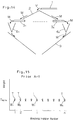
- the first hopper group of the weighing hoppers 61 to 63, 69 and 610 having the smaller respective target supply values T1 to T3, T9 and T10 are positioned on a right-hand side with respect to the center 0 of the dispensing feeder 2 whereas the second hopper group of the weighing hoppers 64 to 68 having the greater respective target supply values T4 to T8 are positioned on a left-hand side with respect to the center 0 of the dispensing feeder 2.
- the target supply values T1 to T10 have a relationship of T1 ⁇ T10 ⁇ T2 ⁇ T9 ⁇ T3 ⁇ T8 ⁇ T4 ⁇ T7 ⁇ T5 ⁇ T6 and that the difference between every two of the target supply values which are numerically close to each other remains the same throughout the target supply values of the weighing hoppers. In other words, re-arrangement of the target supply values T1 to T10 results in the same pattern of the target supply values as shown in Fig. 1.
- the point Q shown in Fig. 6 represents the coordinates where the articles M fall from the delivery conveyor 1 in Fig. 2 and is set at a position offset from the center 0 shown in Fig. 6(b) in a direction close towards the second hopper group of the weighing hoppers 64 to 68 each having the greater target supply value T4 to T8. For this reason, the delivery conveyor 1 allows the articles M, shown in Fig.
- this modification although the amount of supply of the articles M from the dispensing feeder 2 onto the driving feeders 3 i varies from one driving feeder to another, this amount of supply of the articles M can easily become equal to or generally equal to the target supply value T i . Accordingly, the measured weight W i corresponding to the target supply value T i can be obtained easily.
- Fig. 7(a) there is shown another modification of the present invention.
- the weighing hoppers 61 to 6 n are so disposed around the round dispensing feeder 2 that the weighing hoppers 6 i having the smaller respective target supply values T i and the weighing hoppers 6 i having the greater respective target supply values T i alternate with each other circumferentially of the dispensing feeder 2.
- the target supply values T1 to T10 have a relationship of T1 ⁇ T9 ⁇ T3 ⁇ T7 ⁇ T5 ⁇ T6 ⁇ T4 ⁇ T8 ⁇ T2 ⁇ T10 and that the difference between every two of the target supply values which are numerically close to each other remains the same throughout the target supply values of the weighing hoppers.
- re-arrangement of the target supply values T1 to T10 shown in Fig. 7 results in the same pattern of the target supply values as shown in Fig. 1.
- the weighing hoppers each having a relatively large difference between the associated target supply value and the average weight Ta are neighboring with each other while the weighing hoppers each having a relatively small difference between the associated target supply value and the average weight Ta are neighboring with each other.
- are preferably neighboring with each other while the weighing hoppers 6 i having a relatively small value of
- the target supply value T i has been described as detennined from the previously discussed equation (3) on the basis of the combined target supply value T M , the ideal number m of the weighing hoppers to be combined and the total number n of the weighing hoppers to be used. It is, however, to be noted that, in accordance with the present invention, in place of the combined target weight T M and the ideal number m of the weighing hoppers, the average value Ta of the target supply values may be inputted to the target supply value calculating means 30 so that the latter can calculate the target supply value T i on the basis of the average weight Ta in place of T M /m.
- FIG. 8 A second preferred embodiment of the present invention is shown in Fig. 8.
- the parameter setting means 20 is not provided with the target supply value calculating means 30, the inclination coefficient storage means 31, the target supply value control means 32 and the uppermost and lowermost limit value storage means 33 all of which have been described as employed in the parameter setting means 20 according to the foregoing embodiment of the present invention as shown in Fig. 4.
- the target supply value storage means 24 is connected to a manipulatable input means 50 through which an operator can input the target supply value T i .
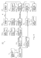
- FIG. 9 illustrates a schematic structural diagram of the parameter setting means 20 (Fig. 3) designed according to the third embodiment of the present invention.
- the parameter setting means 20 includes a number n of the measured weight storage means 21 i , the average measured weight calculating means 22 i and the supply excess/short determining means 23 i in association with each weighing hopper.
- the measured weight storage means 21 i and the average measured weight calculating means 22 i are operable to supply the measured weight W ij and the average measured weight W ia to an actual standard deviation calculating means 40 i , respectively.
- the actual standard deviation calculating means 40 i constitutes, in the case of the illustrated embodiment, a deviation calculating means for calculating the magnitude of deviation of the measured weight W i1 to W iN , outputted from each weighing hopper 6 i , on the basis of the associated weights W i1 to W iN measured during the previous weighing cycles (N times) and outputs the actual standard deviation ⁇ i , actually determined for each weighing hopper 6 i , to a target supply value control means 32B.
- the target supply value control means 32B calculates the coefficient A of inclination which is subsequently outputted therefrom to the target supply value calculating means 30 to control the target supply value calculating means 30.
- the target supply value calculating means 30 makes use of the coefficient A of inclination supplied from the target supply value control means 32B to calculate the target supply value T i according to the previously described equation (3) and then outputs the calculated target supply value T i to the target supply value storage means 24 for the storage thereof.
- Other structural features than those described above are substantially similar to those shown in and described in connection with the first preferred embodiment of the present invention and, therefore, the details are not herein reiterated for the sake of brevity while like parts are designated by like reference numerals.
- the coefficient A of inclination becomes great. Accordingly, it does hardly occur that the measured weights W1 to W n outputted from the respective weighing hoppers 6 i to 6 n will take the same value, and therefore, the combinational selected weight Ws approximating to the combined target weight TM can be obtained easily.
- the measured weights W i1 to W iN for the respective weighing hoppers 6 i deviate considerably largely, that is, if the average value ⁇ a shown in the equation (7) takes a value greater than 6, the coefficient A of inclination becomes zero.
- the measured weight W i takes a value deviated from the target supply value T i , the measured weight W i can take various values even though the coefficient A of inclination is zero, and therefore, the measured weights W1 to W n take respective values differing from each other.
- the coefficient A of inclination has been shown and described as determined based on the average value ⁇ a of the actual standard deviations ⁇ i .
- the coefficient A of inclination may be determined using the minimum or maximum value of the actual standard deviations ⁇ 1 to ⁇ n , or using a value such as a D value, as will be described later, representative of the magnitude of deviation other than the actual standard deviation ⁇ i .
- FIG. 11 schematically illustrates the parameter setting means 20 (Fig. 3) according to this fourth embodiment.
- the parameter setting means 20 shown therein is similar to that employed in the practice of the third embodiment of the present invention and includes the measured weight storage means 21 i , the average measured weight calculating means 22 i , the supply excess/short determining means 23 i , the actual standard deviation calculating means 40 i , the target supply value control means 32B and the target supply value calculating means 30.
- the actual standard deviation calculating means 40 i associated with each weighing hopper 6 i outputs the respective actual standard deviation ⁇ i to both of the target supply value control means 32B and the deviation determining means 41 i .
- the deviation determining means 41 i reads out the target standard deviation ⁇ t, which has been inputted to and stored in a target standard deviation storage means 42, from such target standard deviation storage means 42 and then compare the actual standard deviation ⁇ i with the target standard deviation ⁇ t so that it can be determined if the respective weights of the articles M supplied into the weighing hoppers 6 i are deviated from each other such as shown in a pattern of distribution of Fig. 10(b). In other words, the deviation determining means 41 i shown in Fig.
- the deviation determining means 41 i outputs a deviation excess/short signal d to a deviation coefficient setting means 43 i according to the magnitude of deviation so determined by the deviation determining means 41 i .
- the deviation coefficient setting means 43 i calculates a new deviation coefficient B i + ⁇ B on the basis of the deviation coefficient B i for the previous weighing cycle, which is supplied from the deviation coefficient storage means 44 i , and the deviation excess/short signal d outputted from the deviation determining means 41 i .
- the deviation coefficient setting means 43 i subtracts a single unit from the deviation coefficient B i for the previous weighing cycle to determine the new deviation coefficient B i + ⁇ B (in such case, ⁇ B being a negative value), but should the actual standard deviation ⁇ i be smaller than the target standard deviation ⁇ t, it adds a single unit to the deviation coefficient B i for the previous weighing cycle to determine the new deviation coefficient B i + ⁇ B (in such case, ⁇ B being a positive value).
- the new deviation coefficient B i + ⁇ B referred to above is supplied from the deviation coefficient setting means 43 i to both of the deviation coefficient storage means 44 i and a deviation parameter calculating means 25B i .
- the supply excess/short determining means 23 i compares the target supply value T i , supplied from the target supply value storage means 24, with the average measured weight W ia supplied from the average measured weight calculating means 22 i to provide a supply excess/short signal b to a standard parameter setting means 25A i .
- the standard parameter setting means 25A i referred to above is operable to calculate a new standard parameter P i a + ⁇ P i based on an average parameter P i a, calculated by the average parameter calculating means 45 i during the previous weighing cycles (for example, during the weighing cycles preceding the current weighing cycle) and the supply excess/short signal b supplied from the supply excess/short determining means 23 i .
- the average parameter P i a referred to above is a statistically averaged parameter of the parameters P i1 to P iN .
- the parameters P i1 to P iN calculated prior to the current weighing cycle are stored in the parameter storage means 46 i and are selectively read out by the average parameter calculating means 45 i .
- the deviation parameter calculating means 25B i calculates the new parameter P i on the basis of the average parameter P i a + ⁇ P i and the magnitude of the deviation of the measured weights W ij .
- the new parameter P i since the new parameter P i is calculated by multiplying the standard parameter P i + ⁇ P i by the random number Rn ⁇ (B i + ⁇ B), the new parameter P i will not take a value corresponding to the target supply value T i as shown in Fig. 10(a). Because of this feature, even the actual supply amount W i having a correlation that is generally proportional to the new parameter P i can positively take a value diverting from the target supply value T i . Accordingly, the calculated combination weight W M that can be obtained by combining an arbitrarily chosen number m of the measured weights W i can take a varying value and, therefore, a combinational weighing result close to the target combined value T M can be obtained.
- the measured weight W i may take a null value (indicative of an occurrence of the empty weighing hopper 6 i ) or the excessively loaded weighing hopper 6 i which can hardly be selected for the combination may occur.
- the deviation determining means 41 i determines the magnitude of deviation from the weights W ij measured prior to the current weighing cycle and, based on the result of determination given by the deviation determining means 41 i , the deviation coefficient setting means 43 i modifies the deviation coefficient B i for the previous weighing cycle to provide the new deviation coefficient B i + ⁇ B. Accordingly, as shown in Fig. 10(b), the measured weights W ij to W iN for the respective weighing hoppers 6 i can easily take respective values varying as shown in the pattern of distribution of Fig. 10(b) and, also, the possibility that the empty or excessively loaded weighing hopper 6 i may occur is advantageously minimized.
- the target standard deviation ⁇ t may be of a value differing from one weighing hopper 6 i to another weighing hopper 6 i .
- the target standard deviation ⁇ t i may be registered in terms of a function including the target supply value T i as an independent valuable. In such case, the target standard deviation ⁇ t i may be automatically updated with a change of the target supply value T i .
- the parameter setting means 20 shown therein includes such component means as shown by the solid lines in Fig. 12.
- the measured weight storage means 21 i receive the respective measured weights W i fed from the corresponding hopper weight measuring devices 7 i and store the measured weights W i1 to W iN measured during the N cycles preceding the current cycle. In other words, the measured weight storage means 21 i store, as shown in Fig. 13(a), the measured weights W i1 to W iN measured by the associated hopper weight measuring devices 7 i during the first to N-th cycles prior to the current cycle.
- the deviation determining means 41 i reads out the target standard deviation ⁇ t inputted to and stored in the target standard deviation storage means 42 and compares the target standard deviation ⁇ t with the actual standard deviation ⁇ i to determine if the weights of the articles M supplied into the weighing hoppers 6 i vary as shown by a pattern of distribution shown in Fig. 1(d).
- the target supply value storage means 24A employed in the fifth embodiment of the present invention supplies the same target supply value T for all of the weighing hoppers 6 i to 6 n to the supply short/excess determining means 23 i .
- the target supply value T is determined by the target supply value calculating means 30A by dividing the target combined value T M by the hopper number m and is stored in the target supply value storage means 24A.
- the standard parameter setting means 25A i performs the equation (8) referred to hereinbefore to determine the previous average parameter P i a (calculated, for example, until the preceding cycle) supplied from the average parameter calculating means 45 i .
- a new standard parameter P i a + ⁇ P i is determined, for example, by the following manner. If the average measured weight W ia is greater than the target supply value T, the standard parameter setting means 25A i subtracts one unit from the average parameter P i a calculated according to the equation (8) to determine the new standard parameter P i a + ⁇ P i (in such case, ⁇ P i is a negative value), whereas if the average measured weight W ia is smaller than the target supply value T, the standard parameter setting means 25A i adds one unit to the average parameter P i a calculated according to the equation (8) to determine the new standard parameter P i a + ⁇ P i (in such case, ⁇ P i is a positive value). The new standard parameter P i a + ⁇ P i is outputted from the standard parameter setting means 25A i to the deviation parameter calculating means 25B i .
- the deviation parameter calculating means 25B i calculates the parameter P i for the subsequent weighing cycle according to the previously discussed equation (9).
- the new parameter P i is determined by multiplying the standard parameter P i a + ⁇ P i by a random number Rn ⁇ (B i + ⁇ B), the new parameter P i does not take a value corresponding to the target supply value T as shown in Fig. 1(c).
- the actual supply weights W i which is substantially proportional to the new parameter P i are apt to take varying values relative to the target supply value T.
- the combinational calculated weights W M obtained by combining an arbitrarily chosen number m of the measured weights W i can take various values and, therefore, the result approximating to the target combined value T M can be obtained.
- the combinational weighing apparatus according to this embodiment of the present invention, the use has been made of the deviation determining means 41 i to determine the degree of deviation on the basis of the measured weights W i1 to W iN calculated up until the preceding weighing cycle and, based on the result of determination done by the deviation determining means 41 i , the deviation coefficient setting means 43 i modifies the deviation coefficient B i for the previous weighing cycle to provide the new deviation coefficient B i + ⁇ B and multiplies the standard parameter P i a + ⁇ P i by a controlled random number Rn ⁇ (B i + ⁇ B) to provide a new parameter P i . Accordingly, as shown by the pattern of distribution in Fig. 1(d), the measured weights W i1 to W iN of the respective weighing hoppers 6 i are apt to properly vary and there is no possibility of some of the weighing hoppers 6 i being excessively loaded or emptied.
- the number of the articles M held in the weighing hoppers 6 i is detected by measuring the weight of the articles M therein, and an appropriate combination of the weighing hoppers 6 i is chosen so as to obtain a combined number of the articles M equal to the target combined count or within the allowance.
- the average measured weight W i a has been determined by arithmetically averaging the weights W i1 to W iN measured N times prior to the preceding weighing cycle.
- the average measured weight W i a may be employed in the form of, not the arithmetically averaged value, any average value such as, for example, the weighed average value in which weight W ij measured immediately before the current weighing cycle is weighed largely.
- the parameter P i is updated for each combinational weighing operation by determining the average measured weight W i a for the N times immediately before the preceding weighing cycle, that is, by determining a moving average.
- the updating of the parameter P i may be carried out periodically once in N cycles of combinational weighing operation.
- the average measured value W i a may not be always determined.
- the target supply value calculating means 30A determines the target supply value T on the basis of the target combined value T M and the ideal number m of the weighing hoppers to be combined.
- the target combined value T instead of the target combined value T M and the ideal hopper number m, the target combined value T may be inputted directly to and stored in the target supply value storage means 24A.
- the target supply values T1 to T n need not always be varied linearly.
- the target supply value T i may be determined as a second or higher-order function of the number i of the associated weighing hopper.
- the target supply values T1 to T n have been shown and described as having different values, some of the target supply values T i may be set to have the same value.
- the magnitude of deviation of the measured weights W ij has been determined by the use of the actual standard deviation ⁇ i
- the use may not be always made of the actual standard deviation ⁇ i in the determination of the magnitude of deviation of the measured weights W ij .
- any other random number such as a uniform random number than the normalized random number may be employed as generated from the random number generating means 47 i .
Landscapes
- Physics & Mathematics (AREA)
- General Physics & Mathematics (AREA)
- Engineering & Computer Science (AREA)
- Mathematical Physics (AREA)
- Theoretical Computer Science (AREA)
- Weight Measurement For Supplying Or Discharging Of Specified Amounts Of Material (AREA)
Applications Claiming Priority (4)
| Application Number | Priority Date | Filing Date | Title |
|---|---|---|---|
| JP24883393A JP3388832B2 (ja) | 1993-09-08 | 1993-09-08 | 組合せ計量または計数方法および組合せ計量または計数装置 |
| JP248833/93 | 1993-09-08 | ||
| JP30346693A JP3388843B2 (ja) | 1993-11-08 | 1993-11-08 | 組合せ計量または計数装置 |
| JP303466/93 | 1993-11-08 |
Publications (2)
| Publication Number | Publication Date |
|---|---|
| EP0642003A1 true EP0642003A1 (fr) | 1995-03-08 |
| EP0642003B1 EP0642003B1 (fr) | 1998-05-27 |
Family
ID=26538964
Family Applications (1)
| Application Number | Title | Priority Date | Filing Date |
|---|---|---|---|
| EP94306609A Expired - Lifetime EP0642003B1 (fr) | 1993-09-08 | 1994-09-08 | Pesage ou comptage combinatoire avec réglage des valeurs de placement ou avec des valeurs différentes |
Country Status (3)
| Country | Link |
|---|---|
| US (1) | US5854446A (fr) |
| EP (1) | EP0642003B1 (fr) |
| DE (1) | DE69410556T2 (fr) |
Families Citing this family (6)
| Publication number | Priority date | Publication date | Assignee | Title |
|---|---|---|---|---|
| JP4245909B2 (ja) * | 2002-11-29 | 2009-04-02 | 株式会社イシダ | 組合せ計量装置 |
| US20060162970A1 (en) * | 2003-07-17 | 2006-07-27 | Petur Gudjonsson | Method and a system for batching items into receptacles |
| JP5015639B2 (ja) * | 2007-03-16 | 2012-08-29 | 勝三 川西 | 連係装置とそれを用いた計量装置、包装装置及び計量包装システム |
| US8546704B1 (en) * | 2010-06-16 | 2013-10-01 | Maurice Minardi | Precise count high volume preform delivery system |
| CN103906693B (zh) * | 2011-10-25 | 2016-02-17 | 钻石工程株式会社 | 粉体供给装置以及粉体供给方法 |
| US9829295B2 (en) * | 2016-01-29 | 2017-11-28 | Jimmie Christopher Todd | Ammunition reloading system |
Citations (4)
| Publication number | Priority date | Publication date | Assignee | Title |
|---|---|---|---|---|
| JPS57160021A (en) * | 1981-03-19 | 1982-10-02 | Ishida Scales Mfg Co Ltd | Automatic weighing device |
| JPS6330725A (ja) * | 1986-07-24 | 1988-02-09 | Anritsu Corp | 組合せ計量装置 |
| EP0298736A2 (fr) * | 1987-07-08 | 1989-01-11 | Yamato Scale Company, Limited | Dispositif pour mettre au point les conditions opérationnelles pour une machine de pesage combinatoire |
| EP0319225A2 (fr) * | 1987-11-30 | 1989-06-07 | Kliklok Corporation | Méthode et appareil pour pesage combinatoire linéaire |
Family Cites Families (11)
| Publication number | Priority date | Publication date | Assignee | Title |
|---|---|---|---|---|
| GB2074329B (en) * | 1980-03-25 | 1984-05-16 | Ishida Scale Mfg Co Ltd | Automatic weighing apparatus |
| JPS5756721A (en) * | 1980-09-22 | 1982-04-05 | Ishida Scales Mfg Co Ltd | Combined measuring or counting method and supply controller used for said method |
| AU545681B2 (en) * | 1981-09-07 | 1985-07-25 | Kabushiki Kaisha Ishida Koki Seisakusho | Method for counting parts |
| JPS58124918A (ja) * | 1982-01-22 | 1983-07-25 | Ishida Scales Mfg Co Ltd | 計量方法 |
| JPS5927425U (ja) * | 1982-08-13 | 1984-02-20 | 株式会社石田衡器製作所 | 組合せ計量装置 |
| JPS59198324A (ja) * | 1983-04-27 | 1984-11-10 | Ishida Scales Mfg Co Ltd | 組合せ計量方法 |
| US4676325A (en) * | 1985-05-10 | 1987-06-30 | Yamato Scale Company, Limited | Combination weighing method with two discharge paths and two target weights |
| JPS6330724A (ja) * | 1986-07-24 | 1988-02-09 | Anritsu Corp | 組合せ計量装置 |
| US4880142A (en) * | 1987-05-12 | 1989-11-14 | Fuji Photo Film Co., Ltd. | Powder weighing mixer and method thereof |
| US4813503A (en) * | 1988-05-31 | 1989-03-21 | Package Machinery Company | Method and apparatus for preparing a blended product charge |
| US5270495A (en) * | 1992-02-28 | 1993-12-14 | Package Machinery Company | Combination weighing machine with feed control |
-
1994
- 1994-09-08 EP EP94306609A patent/EP0642003B1/fr not_active Expired - Lifetime
- 1994-09-08 DE DE69410556T patent/DE69410556T2/de not_active Expired - Lifetime
-
1997
- 1997-10-06 US US08/943,228 patent/US5854446A/en not_active Expired - Fee Related
Patent Citations (4)
| Publication number | Priority date | Publication date | Assignee | Title |
|---|---|---|---|---|
| JPS57160021A (en) * | 1981-03-19 | 1982-10-02 | Ishida Scales Mfg Co Ltd | Automatic weighing device |
| JPS6330725A (ja) * | 1986-07-24 | 1988-02-09 | Anritsu Corp | 組合せ計量装置 |
| EP0298736A2 (fr) * | 1987-07-08 | 1989-01-11 | Yamato Scale Company, Limited | Dispositif pour mettre au point les conditions opérationnelles pour une machine de pesage combinatoire |
| EP0319225A2 (fr) * | 1987-11-30 | 1989-06-07 | Kliklok Corporation | Méthode et appareil pour pesage combinatoire linéaire |
Non-Patent Citations (2)
| Title |
|---|
| PATENT ABSTRACTS OF JAPAN vol. 12, no. 238 (P - 726)<3085> 7 July 1988 (1988-07-07) * |
| PATENT ABSTRACTS OF JAPAN vol. 6, no. 265 (P - 165)<1143> 24 December 1982 (1982-12-24) * |
Also Published As
| Publication number | Publication date |
|---|---|
| US5854446A (en) | 1998-12-29 |
| DE69410556T2 (de) | 1998-11-19 |
| DE69410556D1 (de) | 1998-07-02 |
| EP0642003B1 (fr) | 1998-05-27 |
Similar Documents
| Publication | Publication Date | Title |
|---|---|---|
| US4534428A (en) | Vibratory feeder control for a weighing system | |
| US5596179A (en) | Weighing machine which subtracts tare weights | |
| EP0640814B1 (fr) | Pesage ou comptage combinatoire avec une probabilité élevée de combinaisons | |
| JPWO1993023724A1 (ja) | 風袋重量引き付き組合せ計量装置 | |
| JPWO1995031702A1 (ja) | 組合せ計量装置 | |
| EP3258227B1 (fr) | Appareil transporteur et appareil de pesage combiné | |
| EP0642003B1 (fr) | Pesage ou comptage combinatoire avec réglage des valeurs de placement ou avec des valeurs différentes | |
| JP2001255198A (ja) | 組合せ計量計数装置 | |
| JPH0115807B2 (fr) | ||
| US6310454B1 (en) | Apparatus and control method for feeder system for flowable material | |
| EP0103476B1 (fr) | Méthode de pesage combinatoire et dispositif y relatif | |
| EP2672239B1 (fr) | Balance de combinaison | |
| EP0105756B1 (fr) | Dispositif de pesage combinatoire et méthode | |
| JPH04118528A (ja) | 組合せ計量の装置と方法 | |
| US4630695A (en) | Combinatorial weigher employing double group split logic | |
| JP3388832B2 (ja) | 組合せ計量または計数方法および組合せ計量または計数装置 | |
| JPH0251131B2 (fr) | ||
| JP3254287B2 (ja) | 組合せ計量装置 | |
| JP2002062185A (ja) | 組合せ計量装置 | |
| US4552237A (en) | Combinatorial weighing method and apparatus | |
| JP2003207384A (ja) | 粉粒体計量装置及び粉粒体計量方法 | |
| JPH095150A (ja) | 定量供給装置 | |
| JPH07128124A (ja) | 組合せ計量または計数装置 | |
| JP6647568B2 (ja) | 組合せ計量装置 | |
| JP3088532B2 (ja) | 組合せ秤用追加投入装置及び追加投入制御装置 |
Legal Events
| Date | Code | Title | Description |
|---|---|---|---|
| PUAI | Public reference made under article 153(3) epc to a published international application that has entered the european phase |
Free format text: ORIGINAL CODE: 0009012 |
|
| AK | Designated contracting states |
Kind code of ref document: A1 Designated state(s): DE FR GB IT |
|
| 17P | Request for examination filed |
Effective date: 19950501 |
|
| 17Q | First examination report despatched |
Effective date: 19970226 |
|
| GRAG | Despatch of communication of intention to grant |
Free format text: ORIGINAL CODE: EPIDOS AGRA |
|
| GRAG | Despatch of communication of intention to grant |
Free format text: ORIGINAL CODE: EPIDOS AGRA |
|
| GRAH | Despatch of communication of intention to grant a patent |
Free format text: ORIGINAL CODE: EPIDOS IGRA |
|
| GRAH | Despatch of communication of intention to grant a patent |
Free format text: ORIGINAL CODE: EPIDOS IGRA |
|
| GRAA | (expected) grant |
Free format text: ORIGINAL CODE: 0009210 |
|
| AK | Designated contracting states |
Kind code of ref document: B1 Designated state(s): DE FR GB IT |
|
| ET | Fr: translation filed | ||
| REF | Corresponds to: |
Ref document number: 69410556 Country of ref document: DE Date of ref document: 19980702 |
|
| ITF | It: translation for a ep patent filed | ||
| PLBE | No opposition filed within time limit |
Free format text: ORIGINAL CODE: 0009261 |
|
| STAA | Information on the status of an ep patent application or granted ep patent |
Free format text: STATUS: NO OPPOSITION FILED WITHIN TIME LIMIT |
|
| 26N | No opposition filed | ||
| REG | Reference to a national code |
Ref country code: GB Ref legal event code: IF02 |
|
| PGFP | Annual fee paid to national office [announced via postgrant information from national office to epo] |
Ref country code: IT Payment date: 20100918 Year of fee payment: 17 Ref country code: FR Payment date: 20100921 Year of fee payment: 17 |
|
| PGFP | Annual fee paid to national office [announced via postgrant information from national office to epo] |
Ref country code: GB Payment date: 20100908 Year of fee payment: 17 |
|
| PGFP | Annual fee paid to national office [announced via postgrant information from national office to epo] |
Ref country code: DE Payment date: 20100901 Year of fee payment: 17 |
|
| GBPC | Gb: european patent ceased through non-payment of renewal fee |
Effective date: 20110908 |
|
| PG25 | Lapsed in a contracting state [announced via postgrant information from national office to epo] |
Ref country code: IT Free format text: LAPSE BECAUSE OF NON-PAYMENT OF DUE FEES Effective date: 20110908 |
|
| REG | Reference to a national code |
Ref country code: FR Ref legal event code: ST Effective date: 20120531 |
|
| REG | Reference to a national code |
Ref country code: DE Ref legal event code: R119 Ref document number: 69410556 Country of ref document: DE Effective date: 20120403 |
|
| PG25 | Lapsed in a contracting state [announced via postgrant information from national office to epo] |
Ref country code: DE Free format text: LAPSE BECAUSE OF NON-PAYMENT OF DUE FEES Effective date: 20120403 |
|
| PG25 | Lapsed in a contracting state [announced via postgrant information from national office to epo] |
Ref country code: GB Free format text: LAPSE BECAUSE OF NON-PAYMENT OF DUE FEES Effective date: 20110908 Ref country code: FR Free format text: LAPSE BECAUSE OF NON-PAYMENT OF DUE FEES Effective date: 20110930 |