EP0643236B1 - Anker - Zusammenbau einer elektromagnetischen Kupplung anpassungsfähig an verscheidene Arten von Naben - Google Patents
Anker - Zusammenbau einer elektromagnetischen Kupplung anpassungsfähig an verscheidene Arten von Naben Download PDFInfo
- Publication number
- EP0643236B1 EP0643236B1 EP94306652A EP94306652A EP0643236B1 EP 0643236 B1 EP0643236 B1 EP 0643236B1 EP 94306652 A EP94306652 A EP 94306652A EP 94306652 A EP94306652 A EP 94306652A EP 0643236 B1 EP0643236 B1 EP 0643236B1
- Authority
- EP
- European Patent Office
- Prior art keywords
- hub
- disc
- armature assembly
- shaft
- hole
- Prior art date
- Legal status (The legal status is an assumption and is not a legal conclusion. Google has not performed a legal analysis and makes no representation as to the accuracy of the status listed.)
- Expired - Lifetime
Links
- 230000008878 coupling Effects 0.000 title claims description 8
- 238000010168 coupling process Methods 0.000 title claims description 8
- 238000005859 coupling reaction Methods 0.000 title claims description 8
- 241000239290 Araneae Species 0.000 claims description 20
- 239000004033 plastic Substances 0.000 claims description 10
- 230000002093 peripheral effect Effects 0.000 claims description 9
- 239000000463 material Substances 0.000 claims description 6
- 210000001331 nose Anatomy 0.000 description 10
- 238000000465 moulding Methods 0.000 description 8
- 230000000712 assembly Effects 0.000 description 6
- 238000000429 assembly Methods 0.000 description 6
- 230000000694 effects Effects 0.000 description 3
- 238000010276 construction Methods 0.000 description 2
- 210000003128 head Anatomy 0.000 description 2
- 230000004048 modification Effects 0.000 description 2
- 238000012986 modification Methods 0.000 description 2
- 239000012255 powdered metal Substances 0.000 description 2
- 229910000831 Steel Inorganic materials 0.000 description 1
- 239000004957 Zytel Substances 0.000 description 1
- 229920006102 Zytel® Polymers 0.000 description 1
- 238000004378 air conditioning Methods 0.000 description 1
- 230000015572 biosynthetic process Effects 0.000 description 1
- 238000006243 chemical reaction Methods 0.000 description 1
- 230000000295 complement effect Effects 0.000 description 1
- 230000004907 flux Effects 0.000 description 1
- 238000002347 injection Methods 0.000 description 1
- 239000007924 injection Substances 0.000 description 1
- 238000004519 manufacturing process Methods 0.000 description 1
- 239000010959 steel Substances 0.000 description 1
- 238000004804 winding Methods 0.000 description 1
Images
Classifications
-
- F—MECHANICAL ENGINEERING; LIGHTING; HEATING; WEAPONS; BLASTING
- F16—ENGINEERING ELEMENTS AND UNITS; GENERAL MEASURES FOR PRODUCING AND MAINTAINING EFFECTIVE FUNCTIONING OF MACHINES OR INSTALLATIONS; THERMAL INSULATION IN GENERAL
- F16D—COUPLINGS FOR TRANSMITTING ROTATION; CLUTCHES; BRAKES
- F16D27/00—Magnetically- or electrically- actuated clutches; Control or electric circuits therefor
- F16D27/14—Details
-
- F—MECHANICAL ENGINEERING; LIGHTING; HEATING; WEAPONS; BLASTING
- F16—ENGINEERING ELEMENTS AND UNITS; GENERAL MEASURES FOR PRODUCING AND MAINTAINING EFFECTIVE FUNCTIONING OF MACHINES OR INSTALLATIONS; THERMAL INSULATION IN GENERAL
- F16D—COUPLINGS FOR TRANSMITTING ROTATION; CLUTCHES; BRAKES
- F16D27/00—Magnetically- or electrically- actuated clutches; Control or electric circuits therefor
- F16D27/10—Magnetically- or electrically- actuated clutches; Control or electric circuits therefor with an electromagnet not rotating with a clutching member, i.e. without collecting rings
- F16D27/108—Magnetically- or electrically- actuated clutches; Control or electric circuits therefor with an electromagnet not rotating with a clutching member, i.e. without collecting rings with axially movable clutching members
- F16D27/112—Magnetically- or electrically- actuated clutches; Control or electric circuits therefor with an electromagnet not rotating with a clutching member, i.e. without collecting rings with axially movable clutching members with flat friction surfaces, e.g. discs
-
- Y—GENERAL TAGGING OF NEW TECHNOLOGICAL DEVELOPMENTS; GENERAL TAGGING OF CROSS-SECTIONAL TECHNOLOGIES SPANNING OVER SEVERAL SECTIONS OF THE IPC; TECHNICAL SUBJECTS COVERED BY FORMER USPC CROSS-REFERENCE ART COLLECTIONS [XRACs] AND DIGESTS
- Y10—TECHNICAL SUBJECTS COVERED BY FORMER USPC
- Y10T—TECHNICAL SUBJECTS COVERED BY FORMER US CLASSIFICATION
- Y10T403/00—Joints and connections
- Y10T403/10—Selectively engageable hub to shaft connection
Definitions
- This invention relates generally to an electromagnetic coupling such as a clutch or brake and, more particularly, to an armature assembly for such a coupling.
- Booth et al United States Patent No. 5,036,964 and Booth United States Patent No. 5,150,779 each disclose an electromagnetic clutch in which an armature is connected to a driven hub on a rotatable shaft and is adapted to be frictionally coupled to a driving rotor when an electromagnet is energized to engage the clutch. When the clutch is engaged, the rotor acts through the armature to rotate the driven hub and the shaft.
- the armature assembly disclosed in each of the aforementioned patents includes a resilient plastic spider with a web which acts to connect a low magnetic reluctance armature plate for rotation with the driven hub.
- the web flexes axially in order to permit the armature plate to move toward and away from the rotor when the clutch is engaged and disengaged.
- the hub is insert molded in place when the spider is molded and thus the plastic of the spider is bonded to and encapsulates part of the hub in order to join the hub to the spider.
- Clutches are used with different types of shafts which require different types of armature hubs. As a result, it has been necessary in the past to customize various armature assemblies having different types of hubs molded in place in the spider. A substantial tooling investment is required to achieve this and, in addition, several different types of customized armature assemblies must be maintained in inventory.
- the general aim of the present invention is to provide a new and improved armature assembly of the foregoing general character which is more universally adaptable to different types of hubs and shafts so as to reduce the cost of both producing and inventorying armature assemblies.
- a more detailed object of the invention is to achieve the foregoing by standardizing the resiliently yieldable spider of the armature assembly and by insert molding a relatively simple mounting disc in the spider, the mounting disc being adapted for assembly with a separately formed hub.
- the external configuration of mounting discs for various types of hubs is identical and thus substantially common tooling may be used to effect insert molding of the mounting discs.
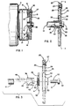
- FIGURE 1 is a side elevational view of a typical electromagnetic coupling equipped with a new and improved armature assembly incorporating the unique features of the present invention, certain parts of the coupling being broken away and shown in section.
- FIG. 2 is an enlarged view of the shaft, hub and armature assembly shown in FIG. 1.
- FIG. 3 is an exploded view of the components shown in FIG. 2.
- FIG. 4 is a cross-section, on a reduced scale, taken substantially along the line 4-4 of FIG. 2.
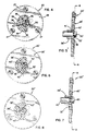
- FIG. 5 is a view generally similar to FIG. 2 but shows a modified hub and armature assembly.
- FIG. 6 is a cross-section, on a reduced scale, taken substantially along the line 6-6 of FIG. 5.
- FIG. 7 is another view generally similar to FIG. 2 but shows still another modified hub and armature assembly.
- FIG. 8 is a cross-section, on a reduced scale, taken substantially along the line 8-8 of FIG. 7.
- an electromagnetic coupling 10 which could be a brake but which herein is in the form of an electromagnetic clutch.
- the clutch 10 is shown as being used in conjunction with a vehicular air conditioning compressor 11 having a rotatable drive shaft 12.
- the clutch 10 includes an electromagnet which is formed in part by a rotor 13 coaxial with the shaft 12 and adapted to be driven by an endless belt 14. Located in opposing relation with a face 15 of the rotor is an armature assembly 20. When a winding 21 is excited, magnetic flux draws part of the armature assembly into frictional engagement with the rotor face 15 so as to couple the armature assembly and the rotor for rotation in unison. Rotation of the armature assembly is transmitted to the shaft 12 in order to drive the compressor 11.
- the armature assembly 20 is similar to that disclosed in Booth United States Patent No. 5,150,779.
- the armature assembly includes a spider 25 which is injection molded of resiliently yieldable material such as plastic.
- a suitable material for the spider is Dupont Zytel ST 801-HS.
- the spider 25 includes a web 26 which is preferably circular and which is comparatively thin in the axial direction so that the web is capable of flexing axially.
- a web 26 Connected by angularly spaced rivets 27 to the outer peripheral portion of the web is an annular disc or plate 29 which forms the actual armature of the armature assembly 20.
- the plate 29 is made of low magnetic reluctance material such as AISI 1010 steel and is normally spaced axially from the rotor face 15 as shown in FIG. 1.
- the web 26 flexes to allow the armature plate to be drawn axially into coupling engagement with the rotor face.
- annular mounting sleeve 30 Molded integrally with the inner peripheral portion of the web 26 is an annular mounting sleeve 30 having a centrally located and axially extending hole 31 (FIG. 3) therein.
- the relatively thin web 26 is capable of flexing axially relative to the sleeve 30.
- a relatively simple mounting disc 35 is joined intimately to the sleeve 30 of the spider 25.
- the mounting disc is adapted to be secured to a tubular hub 36 which, in turn, is coupled to the compressor shaft 12.
- the use of the mounting disc 35 and the separately formed hub 36 allows for more economical manufacture of armature assemblies 20 useable with different types of hubs and shafts and reduces the number of types of armature assemblies which must be made and inventoried in order to accommodate various types of hub and shaft configurations.
- the mounting disc 35 is preferably but not necessarily made of powdered metal.
- the disc is comparatively thin in the axial direction and its outer periphery is formed with a series of angularly spaced and radially projecting lugs 38 (FIG. 4) which are separated by intervening spaces.
- the disc is insert molded in place when the spider 25 is molded and, during the molding operation, plastic of the sleeve 30 flows into and fills the spaces between the lugs. When the plastic cures, it encapsulates and becomes bonded intimately to the outer peripheral portion of the disc 35 and its angularly spaced lugs 36. By virtue of being bonded to the lugs and filling the spaces therebetween, the plastic couples the spider and the disc for rotation in unison.
- the hub 36 is formed separately of the mounting disc 35 and also may be made of powdered metal.
- the hub is in the form of a relatively long sleeve whose forward end portion or nose 43 is externally threaded.
- a comparatively small diameter hole 44 (FIG. 3) is formed in the forward end portion of the hub while a larger counterbore 45 is formed in the rear end portion of the hub and is sized to telescopically receive the shaft 12.
- a key 46 is adapted to fit in keyways formed in the hub and the shaft in order to couple the hub for rotation with the shaft.
- a threaded bore 47 (FIG. 2) is formed in the shaft and opens axially out of the free end thereof.
- the spider 25 with the molded in place mounting disc 35 may be assembled to the hub 36 by screwing the disc tightly onto the externally threaded nose 43 of the hub. Thereafter, the hub may be telescoped onto the shaft 12 and coupled for rotation therewith by the key 46.
- a screw 50 having a threaded shank 51 and a head 52, the shank being sized to slip through a washer 53.
- the shank 51 of the screw is extended through the hole 44 and the counterbore 45 in the hub 36 and is threaded into the bore 47 in the shaft 12.
- its head 52 presses the washer 53 against the end of the nose 43 of the hub in order to clamp the bottom of the counterbore against the end of the shaft and thereby captivate the armature assembly on the shaft.
- the hub 36' is somewhat shorter than the hub 36 and, rather than having an externally threaded nose 43, is formed with a hexagonally-shaped nose 43', there being an annular shoulder 55 (FIG. 5) at the rear end of the nose.
- the disc 35' is formed with a central hole 40' (FIG. 6) which also is shaped as a hex.
- the washer 53' engages the forward face of the disc 35' and clamps the collar 41' of the disc against the shoulder 55 of the hub in order to captivate the disc axially on the hub.
- either the hub 36 or the hub 36' may be formed with an internally tapered bore so as to mate with a tapered compressor shaft.
- the discs 35 and 35' may be used universally with either tapered or non-tapered hubs and also may be used universally with internally splined hubs or smooth bored hubs.
- FIGS. 7 and 8 Still another embodiment of an armature assembly 20'' is shown in FIGS. 7 and 8.
- the hub 36'' is formed with a cylindrical nose 43'' and thus the disc 35'' is formed with a complementary cylindrical hole 40''.
- Rotation of the disc 35'' relative to the hub 36'' is prevented by a circumferentially continuous laser weld 60 (FIG. 8) which joins the outer end of the nose 43'' to the edge of the hole 40''.
Landscapes
- Engineering & Computer Science (AREA)
- General Engineering & Computer Science (AREA)
- Mechanical Engineering (AREA)
- Physics & Mathematics (AREA)
- Electromagnetism (AREA)
- Braking Arrangements (AREA)
- Mechanical Operated Clutches (AREA)
Claims (7)
- Ankeranordnung (20) zum Einsatz mit einer elektromagnetischen Kupplung (10), welche eine drehbare Welle (12) hat, wobei die Ankeranordnung einen im allgemeinen kreisförmigen Kern (25) aufweist, welcher einen Steg (26) hat, der aus einem federnd nachgiebigen, biegbaren Kunststoffmaterial hergestellt ist, und eine zentral angeordnete Öffnung (31) hat, welche axial denselben durchsetzt, ferner eine ringförmige Ankerplatte (29) aus Material mit niedriger magnetischer Reluktanz aufweist, welche fest mit dem äußeren Umfangsteil des Stegs verbunden ist, eine Befestigungsscheibe (35) aufweist, welche in der Öffnung angeordnet ist und eng sitzend mit dem Kern verbunden ist, wobei die Scheibe eine zentrisch liegende Öffnung (40) hat, welche axial durch dieselbe geht, sowie eine rohrförmige Nabe (36), welche gesondert von der Scheibe ausgebildet und durch die Öffnung in der Scheibe durchgeführt ist, wobei die Nabe derart bemessen und ausgebildet ist, daß sie teleskopartig auf der Welle anordenbar ist, eine erste Einrichtung, welche verhindert, daß sich die Scheibe relativ zu der Nabe bewegt, und eine zweite Einrichtung aufweist, welche verhindert, daß die Nabe sich relativ zu der Welle (46) bewegt.
- Ankeranordnung (20) nach Anspruch 1, bei der die erste Einrichtung ein Innengewinde in der Öffnung (40) der Scheibe (35) und ferner ein Außengewinde auf der Nabe (36) aufweist, welches in Gewindeeingriff mit dem Innengewinde ist.
- Ankeranordnung (20) nach Anspruch 1, bei der die erste Einrichtung teilweise durch den Rand der Öffnung (40) in der Scheibe (35') gebildet wird, der Rand nicht kreisförmig ausgebildet ist, und die erste Einrichtung ebenfalls teilweise durch eine nicht kreisförmige Umfangsfläche der Nabe (36') gebildet wird, welche mit dem Rand zusammenarbeitet, um eine Verdrehung der Scheibe auf der Nabe zu verhindern.
- Ankeranordnung (20") nach Anspruch 1, bei der die erste Einrichtung wenigstens teilweise durch eine Schweißung (60) zwischen der Scheibe (35") und der Nabe (36") gebildet wird.
- Ankeranordnung (20) nach Anspruch 1, bei der die zweite Einrichtung einen Keil (46) aufweist, welcher zwischen der Nabe (36) und der Welle (12) angeordnet ist und verhindert, daß die Nabe sich auf der Welle dreht.
- Ankeranordnung (20) nach Anspruch 5, bei der die zweite Einrichtung ferner eine Schraube (50) aufweist, welche derart beschaffen und ausgelegt ist, daß sie axial in das Ende der Welle (12) mittels einer Gewindeverbindung greift und eine Einrichtung (3) hat, welche die Nabe (36) axial auf der Welle festlegt.
- Ankeranordnung (20) nach Anspruch 1, bei der der Steg innere und äußere Umfangsteile hat, eine Hülse (30) vorgesehen ist, welche integral mit dem inneren Umfangsteil des Stegs ausgebildet ist, die mittig angeordnete Öffnung (31) durch die Hülse ausgebildet ist, die Befestigungsscheibe (35), welche einen Außenumfangsteil hat, welcher von einer Reihe von in Winkelrichtung beabstandeten Ansätzen (38) und dazwischenliegenden Zwischenräumen gebildet wird, wobei das äußere Umfangsteil der Scheibe in der Hülse angeordnet ist und die Zwischenräume mit Kunststoffmaterial ausgefüllt sind, und das Kunststoffmaterial innig mit den Ansätzen verbunden ist.
Applications Claiming Priority (2)
| Application Number | Priority Date | Filing Date | Title |
|---|---|---|---|
| US119729 | 1993-09-10 | ||
| US08/119,729 US5370209A (en) | 1993-09-10 | 1993-09-10 | Electromagnetic coupling armature assembly adaptable to various types of hubs |
Publications (2)
| Publication Number | Publication Date |
|---|---|
| EP0643236A1 EP0643236A1 (de) | 1995-03-15 |
| EP0643236B1 true EP0643236B1 (de) | 1997-01-29 |
Family
ID=22386013
Family Applications (1)
| Application Number | Title | Priority Date | Filing Date |
|---|---|---|---|
| EP94306652A Expired - Lifetime EP0643236B1 (de) | 1993-09-10 | 1994-09-09 | Anker - Zusammenbau einer elektromagnetischen Kupplung anpassungsfähig an verscheidene Arten von Naben |
Country Status (4)
| Country | Link |
|---|---|
| US (1) | US5370209A (de) |
| EP (1) | EP0643236B1 (de) |
| JP (1) | JPH07269601A (de) |
| DE (1) | DE69401628T2 (de) |
Families Citing this family (6)
| Publication number | Priority date | Publication date | Assignee | Title |
|---|---|---|---|---|
| US5632366A (en) * | 1996-03-13 | 1997-05-27 | General Motors Corporation | Electromagnetic clutch with improved torque cushion |
| US5642798A (en) * | 1996-03-22 | 1997-07-01 | General Motors Corporation | Electromagentic compressor clutch with combined torque cushion and armature cooling |
| US6194803B1 (en) | 1998-02-27 | 2001-02-27 | Warner Electric Technology, Inc. | Sound damping armature assembly for an electromagnetic coupling |
| US6129194A (en) * | 1998-08-13 | 2000-10-10 | Warner Electric Technology, Inc. | Electromagnetic coupling armature assembly with counterweight |
| DE202013002597U1 (de) * | 2013-03-18 | 2013-03-26 | Erwin A. Lang Gmbh & Co. Kg | Elektromagnetische Kupplungsvorrichtung |
| DE102014117088A1 (de) * | 2014-11-21 | 2016-05-25 | Kendrion (Markdorf) Gmbh | Kupplung sowie Verfahren zum Einstellen eines Kupplungsluftspaltes |
Family Cites Families (16)
| Publication number | Priority date | Publication date | Assignee | Title |
|---|---|---|---|---|
| US4187939A (en) * | 1977-12-14 | 1980-02-12 | Warner Electric Brake & Clutch Company | Armature assembly for electromagnetic coupling |
| US4493407A (en) * | 1981-12-14 | 1985-01-15 | Warner Electric Brake & Clutch Company | Armature assembly for an electromagnetic clutch |
| US4445606A (en) * | 1981-12-14 | 1984-05-01 | Warner Electric Brake & Clutch Company | Armature assembly for electromagnetic coupling |
| US4642031A (en) * | 1985-05-20 | 1987-02-10 | Tecumseh Products Company | Alternator-compressor construction |
| JPS6319427A (ja) * | 1986-07-10 | 1988-01-27 | Sanden Corp | 電磁クラツチ |
| JPS6323031A (ja) * | 1986-07-14 | 1988-01-30 | Sanden Corp | 電磁クラツチ |
| US4749073A (en) * | 1987-05-11 | 1988-06-07 | Dana Corporation | Soft-start electromagnetic coupling |
| JPH0217229A (ja) * | 1988-07-04 | 1990-01-22 | Toyota Autom Loom Works Ltd | 電磁クラッチの制御方法 |
| JPH0359530U (de) * | 1989-10-13 | 1991-06-12 | ||
| US5036964A (en) * | 1990-03-28 | 1991-08-06 | Dana Corporation | Armature assembly for an electromagnetic coupling |
| US5080214A (en) * | 1990-06-29 | 1992-01-14 | Inertia Dynamics, Inc. | Electromagnetic clutch |
| US5184705A (en) * | 1990-07-16 | 1993-02-09 | Ogura Corporation | Electromagnetic clutch |
| US5250921A (en) * | 1990-10-19 | 1993-10-05 | Dana Corporation | Field assembly for an electromagnet |
| US5052534A (en) * | 1990-10-30 | 1991-10-01 | Dana Corporation | Electromagnetic synchronizing and shifting clutch |
| US5150779A (en) * | 1992-01-14 | 1992-09-29 | Dana Corporation | Armature assembly for an electromagnetic coupling |
| US5195625A (en) * | 1992-05-29 | 1993-03-23 | General Motors Corporation | Torque cushion for electromagnetic clutch |
-
1993
- 1993-09-10 US US08/119,729 patent/US5370209A/en not_active Expired - Lifetime
-
1994
- 1994-09-09 EP EP94306652A patent/EP0643236B1/de not_active Expired - Lifetime
- 1994-09-09 DE DE69401628T patent/DE69401628T2/de not_active Expired - Lifetime
- 1994-09-12 JP JP6254100A patent/JPH07269601A/ja active Pending
Also Published As
| Publication number | Publication date |
|---|---|
| DE69401628T2 (de) | 1997-05-28 |
| US5370209A (en) | 1994-12-06 |
| DE69401628D1 (de) | 1997-03-13 |
| EP0643236A1 (de) | 1995-03-15 |
| JPH07269601A (ja) | 1995-10-20 |
Similar Documents
| Publication | Publication Date | Title |
|---|---|---|
| US5372228A (en) | Sound-damping armature assembly for an electromagnetic coupling | |
| US4828090A (en) | Electromagnetic clutch | |
| GB2243195A (en) | Armature assembly for an electromagnetic coupling | |
| US5305865A (en) | Rotor for electromagnetic coupling | |
| US5119915A (en) | Electromagnetic coupling armature assembly with flux isolator springs | |
| EP0604190B1 (de) | Kupplung mit Distanzhülse für die Befestigung eines Lagers | |
| US20090186728A1 (en) | Power transmission apparatus | |
| EP0953784B1 (de) | Magnetische Brems- und Kupplungseinheit | |
| EP0836026A2 (de) | Elektromagnetische Kupplung | |
| US4793455A (en) | Electromagnetic coupling | |
| US6857835B2 (en) | Wheel end assembly with locking fastener | |
| GB2339861A (en) | Sound damping armature assembly for an electromagnetic coupling | |
| US5370209A (en) | Electromagnetic coupling armature assembly adaptable to various types of hubs | |
| EP0713026B1 (de) | Armaturenanordnung für eine elektromagnetische Kupplung | |
| EP0645550B1 (de) | Elektromagnetische Kupplungsscheibe | |
| US5601176A (en) | Armature assembly in an electromagnetic coupling device | |
| EP1602847B1 (de) | Elektromagnetkupplung | |
| US5310034A (en) | Supporting hub for clutch and pump assembly | |
| KR100898912B1 (ko) | 전자클러치의 디스크 및 허브 조립체의 제조방법 | |
| EP0947719B1 (de) | Servolenksystem | |
| KR20030011795A (ko) | 반경방향 플레이트의 회전 및 병진 운동 방지 방법, 및 그방법에 의한 허브 및 반경방향 플레이트의 조립체 | |
| JPH0625718Y2 (ja) | 電磁クラッチ等におけるアーマチュアとハブの連結構造 | |
| KR100531659B1 (ko) | 전자클러치용 디스크 및 허브 조립체_ | |
| KR20030020564A (ko) | 전자 클러치의 디스크/허브 조립체 및 그 제조방법 | |
| JPH0823375B2 (ja) | 電磁クラツチ |
Legal Events
| Date | Code | Title | Description |
|---|---|---|---|
| PUAI | Public reference made under article 153(3) epc to a published international application that has entered the european phase |
Free format text: ORIGINAL CODE: 0009012 |
|
| AK | Designated contracting states |
Kind code of ref document: A1 Designated state(s): DE FR GB |
|
| 17P | Request for examination filed |
Effective date: 19950908 |
|
| GRAG | Despatch of communication of intention to grant |
Free format text: ORIGINAL CODE: EPIDOS AGRA |
|
| 17Q | First examination report despatched |
Effective date: 19960402 |
|
| GRAH | Despatch of communication of intention to grant a patent |
Free format text: ORIGINAL CODE: EPIDOS IGRA |
|
| GRAH | Despatch of communication of intention to grant a patent |
Free format text: ORIGINAL CODE: EPIDOS IGRA |
|
| GRAA | (expected) grant |
Free format text: ORIGINAL CODE: 0009210 |
|
| AK | Designated contracting states |
Kind code of ref document: B1 Designated state(s): DE FR GB |
|
| REF | Corresponds to: |
Ref document number: 69401628 Country of ref document: DE Date of ref document: 19970313 |
|
| ET | Fr: translation filed | ||
| PLBE | No opposition filed within time limit |
Free format text: ORIGINAL CODE: 0009261 |
|
| STAA | Information on the status of an ep patent application or granted ep patent |
Free format text: STATUS: NO OPPOSITION FILED WITHIN TIME LIMIT |
|
| 26N | No opposition filed | ||
| REG | Reference to a national code |
Ref country code: GB Ref legal event code: IF02 |
|
| REG | Reference to a national code |
Ref country code: GB Ref legal event code: 732E |
|
| PGFP | Annual fee paid to national office [announced via postgrant information from national office to epo] |
Ref country code: GB Payment date: 20090929 Year of fee payment: 16 |
|
| PGFP | Annual fee paid to national office [announced via postgrant information from national office to epo] |
Ref country code: DE Payment date: 20090929 Year of fee payment: 16 |
|
| GBPC | Gb: european patent ceased through non-payment of renewal fee |
Effective date: 20100909 |
|
| REG | Reference to a national code |
Ref country code: FR Ref legal event code: ST Effective date: 20110531 |
|
| REG | Reference to a national code |
Ref country code: DE Ref legal event code: R119 Ref document number: 69401628 Country of ref document: DE Effective date: 20110401 |
|
| PG25 | Lapsed in a contracting state [announced via postgrant information from national office to epo] |
Ref country code: DE Free format text: LAPSE BECAUSE OF NON-PAYMENT OF DUE FEES Effective date: 20110401 Ref country code: FR Free format text: LAPSE BECAUSE OF NON-PAYMENT OF DUE FEES Effective date: 20100930 |
|
| PG25 | Lapsed in a contracting state [announced via postgrant information from national office to epo] |
Ref country code: GB Free format text: LAPSE BECAUSE OF NON-PAYMENT OF DUE FEES Effective date: 20100909 |
|
| PGFP | Annual fee paid to national office [announced via postgrant information from national office to epo] |
Ref country code: FR Payment date: 20091006 Year of fee payment: 16 |