EP0643633B1 - A method for joining together two or several overlaying sheet formed members, an apparatus for carrying out said method - Google Patents
A method for joining together two or several overlaying sheet formed members, an apparatus for carrying out said method Download PDFInfo
- Publication number
- EP0643633B1 EP0643633B1 EP94913111A EP94913111A EP0643633B1 EP 0643633 B1 EP0643633 B1 EP 0643633B1 EP 94913111 A EP94913111 A EP 94913111A EP 94913111 A EP94913111 A EP 94913111A EP 0643633 B1 EP0643633 B1 EP 0643633B1
- Authority
- EP
- European Patent Office
- Prior art keywords
- punch
- die
- sheet formed
- die cavity
- cup
- Prior art date
- Legal status (The legal status is an assumption and is not a legal conclusion. Google has not performed a legal analysis and makes no representation as to the accuracy of the status listed.)
- Expired - Lifetime
Links
Images


Classifications
-
- B—PERFORMING OPERATIONS; TRANSPORTING
- B21—MECHANICAL METAL-WORKING WITHOUT ESSENTIALLY REMOVING MATERIAL; PUNCHING METAL
- B21D—WORKING OR PROCESSING OF SHEET METAL OR METAL TUBES, RODS OR PROFILES WITHOUT ESSENTIALLY REMOVING MATERIAL; PUNCHING METAL
- B21D39/00—Application of procedures in order to connect objects or parts, e.g. coating with sheet metal otherwise than by plating; Tube expanders
- B21D39/03—Application of procedures in order to connect objects or parts, e.g. coating with sheet metal otherwise than by plating; Tube expanders of sheet metal otherwise than by folding
-
- B—PERFORMING OPERATIONS; TRANSPORTING
- B21—MECHANICAL METAL-WORKING WITHOUT ESSENTIALLY REMOVING MATERIAL; PUNCHING METAL
- B21D—WORKING OR PROCESSING OF SHEET METAL OR METAL TUBES, RODS OR PROFILES WITHOUT ESSENTIALLY REMOVING MATERIAL; PUNCHING METAL
- B21D39/00—Application of procedures in order to connect objects or parts, e.g. coating with sheet metal otherwise than by plating; Tube expanders
- B21D39/03—Application of procedures in order to connect objects or parts, e.g. coating with sheet metal otherwise than by plating; Tube expanders of sheet metal otherwise than by folding
- B21D39/031—Joining superposed plates by locally deforming without slitting or piercing
-
- Y—GENERAL TAGGING OF NEW TECHNOLOGICAL DEVELOPMENTS; GENERAL TAGGING OF CROSS-SECTIONAL TECHNOLOGIES SPANNING OVER SEVERAL SECTIONS OF THE IPC; TECHNICAL SUBJECTS COVERED BY FORMER USPC CROSS-REFERENCE ART COLLECTIONS [XRACs] AND DIGESTS
- Y10—TECHNICAL SUBJECTS COVERED BY FORMER USPC
- Y10T—TECHNICAL SUBJECTS COVERED BY FORMER US CLASSIFICATION
- Y10T29/00—Metal working
- Y10T29/49—Method of mechanical manufacture
- Y10T29/49826—Assembling or joining
- Y10T29/49908—Joining by deforming
- Y10T29/49915—Overedge assembling of seated part
-
- Y—GENERAL TAGGING OF NEW TECHNOLOGICAL DEVELOPMENTS; GENERAL TAGGING OF CROSS-SECTIONAL TECHNOLOGIES SPANNING OVER SEVERAL SECTIONS OF THE IPC; TECHNICAL SUBJECTS COVERED BY FORMER USPC CROSS-REFERENCE ART COLLECTIONS [XRACs] AND DIGESTS
- Y10—TECHNICAL SUBJECTS COVERED BY FORMER USPC
- Y10T—TECHNICAL SUBJECTS COVERED BY FORMER US CLASSIFICATION
- Y10T29/00—Metal working
- Y10T29/49—Method of mechanical manufacture
- Y10T29/49826—Assembling or joining
- Y10T29/49908—Joining by deforming
- Y10T29/49936—Surface interlocking
-
- Y—GENERAL TAGGING OF NEW TECHNOLOGICAL DEVELOPMENTS; GENERAL TAGGING OF CROSS-SECTIONAL TECHNOLOGIES SPANNING OVER SEVERAL SECTIONS OF THE IPC; TECHNICAL SUBJECTS COVERED BY FORMER USPC CROSS-REFERENCE ART COLLECTIONS [XRACs] AND DIGESTS
- Y10—TECHNICAL SUBJECTS COVERED BY FORMER USPC
- Y10T—TECHNICAL SUBJECTS COVERED BY FORMER US CLASSIFICATION
- Y10T29/00—Metal working
- Y10T29/49—Method of mechanical manufacture
- Y10T29/49826—Assembling or joining
- Y10T29/49908—Joining by deforming
- Y10T29/49938—Radially expanding part in cavity, aperture, or hollow body
-
- Y—GENERAL TAGGING OF NEW TECHNOLOGICAL DEVELOPMENTS; GENERAL TAGGING OF CROSS-SECTIONAL TECHNOLOGIES SPANNING OVER SEVERAL SECTIONS OF THE IPC; TECHNICAL SUBJECTS COVERED BY FORMER USPC CROSS-REFERENCE ART COLLECTIONS [XRACs] AND DIGESTS
- Y10—TECHNICAL SUBJECTS COVERED BY FORMER USPC
- Y10T—TECHNICAL SUBJECTS COVERED BY FORMER US CLASSIFICATION
- Y10T29/00—Metal working
- Y10T29/53—Means to assemble or disassemble
- Y10T29/53709—Overedge assembling means
-
- Y—GENERAL TAGGING OF NEW TECHNOLOGICAL DEVELOPMENTS; GENERAL TAGGING OF CROSS-SECTIONAL TECHNOLOGIES SPANNING OVER SEVERAL SECTIONS OF THE IPC; TECHNICAL SUBJECTS COVERED BY FORMER USPC CROSS-REFERENCE ART COLLECTIONS [XRACs] AND DIGESTS
- Y10—TECHNICAL SUBJECTS COVERED BY FORMER USPC
- Y10T—TECHNICAL SUBJECTS COVERED BY FORMER US CLASSIFICATION
- Y10T29/00—Metal working
- Y10T29/53—Means to assemble or disassemble
- Y10T29/53996—Means to assemble or disassemble by deforming
Definitions
- This invention relates to a method for joining together two or several overlaying sheet formed members, an apparatus for carrying out said method and a joint resulting from said method.
- Such joining procedures could e.g. be carried out by first drawing and then laterally extruding the material of the two sheet formed members to be joined into an enlarged shape which will interlock the members.
- a joint produced by means of this method will typically be of the leakproof type.
- the members could also be joined by lancing and forming a part of one member through an unblanked part of the other member and thereafter staking the lanced and formed part of the one member to an adjacent surface of the other member to secure the members together in overlaying relation.
- a joint produced by means of this method will typically be of the non-leakproof type.
- US-A-4 459 735 discloses an apparatus, a method and a joint of this type.
- the method is of the single stroke type which means that the whole procedure takes place during one single relative movement between a punch and a coacting die.
- an anvil is arranged fixed at the bottom of the die cavity which cavity is laterally expandable.
- Double-stroke methods are also known from e.g. WO 89/07020 according to which the compression takes place during a second stroke outside the die cavity. This cavity is generally laterally non-expandable.
- One object of the present invention is to provide a method for joining sheet metal and/or other sheet material producing a joint of the leakproof or non-leakproof type having considerably improved strength in relation to known joints.
- Another object of the invention is to provide an apparatus which is less sensitive to variations in the total thickness of the sheet members.
- the claimed apparatus utilizes a new punch construction which considerably will contribute to the strength of the joint.
- An advantage of the invention is the simplicity of the solution.
- a stroke is defined as the relative approaching between the punch and the die.
- the joint is carried out on two superimposed metal sheets. The lateral expansion of the joint will take place outside the die. It is, however, once again emphasized that the invention is also applicable on single-stroke procedures with laterally flexible or fixed dies and on more than two sheet formed members and for creating non-leakproof joints.
- Figure 1 shows a section through a joint produced by means of a known method with too small gap between the punch and the die cavity.
- the lateral expansion of the bottom wall of the cup-formed or protruding portion is satisfactory.
- the member forming the inner wall of the cup-formed or protruding portion has a good grip inside the mushroom formed cavity in the other member.
- the inner side wall of the cup-formed portion is, due to the drawing of the material, very thin and this part will constitute the weak zone of the joint.
- figure 2 is shown a section through a known joint with too big gap between the punch and the die cavity.
- the lateral expansion of the bottom wall of the cup-formed portion is not satisfactory in this case.
- the member forming the inner wall of the cup-formed portion does not grip sufficiently inside the mushroom formed cavity in the other member. When exposed to forces the members will separate as indicated. The same effect will be created if the drawing depth would be too small.
- the drawing depth and/or the gap between the punch and the die cavity are thus critical to the strength of the joint and have to be carefully chosen with regard to total thickness of the members, material etc.. It is evident that a change of for instance the total thickness, number of sheets etc., if not compensated for, will be detrimental to the quality of the joint.
- Figures 3a-d show, partly in section, the relative movements of a punch, a die and an anvil during a joint forming operation in an apparatus according to an embodiment of the invention.
- the two metal sheets 1,2 to be joined are positioned on top of the die 3.
- a punch 4 is arranged coaxially with the die to cooperate with the same in a relative movement. This is to say that in a machine-fixed coordinate system the die 3 or the punch 4 or both can be moving.
- the relative movement between the punch and the die is the essential.
- Inside the die an anvil 5 is arranged to move coaxially with the die 3 and the punch 4. The relative movement between the anvil and the die is the essential.
- the tip 7 of the core portion 6 of the punch has an essentially cylindrical or sometimes a slightly conical form and can have a circular section perpendicular to the axis or an oval section or any other suitable section.
- the die cavity 9 will have a suitable cooperating section in each case chosen depending on the material thickness, the kind of joint to be produced etc..
- the punch has been activated by means of any suitable drive system, mechanical, pneumatic, hydraulic, electrical etc. and the punch has due to the applied forces drawn the material of the two sheet formed members 1,2 down and into the die cavity 9, thereby creating on the surfaces of the two members a cup-formed or protruding portion 10.
- the anvil 5 which could be spring loaded is moved downwards against the spring force.
- the essentially cylindrical core portion of the punch 6 has been provided with an external extension 8 around its rear end.
- This extension 8 will, by means of the applied forces, deform and displace material from the area around the opening 11 of the created cup-formed portion 10 in the direction of the die 3, thus modifying the weak zone in the sidewall of the joint with the view of an overall reinforcement of said wall, as defined above.
- This deformation and displacement of material will act on both members 1,2 but to the greatest extent on the upper member 1 which is directly acted upon by the punch.
- the anvil 5 is activated by means of a suitable power system to exit the cup-formed portion 10 from the die cavity 9.
- the punch is released and follows the movement of the members upwards.
- the anvil 5 is then locked in a predefined position in which its tip could be flush with the top surface of the die, somewhat protruding over this surface or being positioned somewhat below said surface.
- the tip of the anvil and/or the punch is/are not necessarily flat, but can have ridges or grooves arranged e.g. for increasing the extrusion of the material.
- an lateral extension 8 around the rear end of the core portion 6 of the punch 4 makes it possible to considerably increase the strength of the joint.
- the cross section and dimensions of the extension can be chosen to suit the actual forces applied, the material used, the thickness of the individual sheets, the total thickness, the friction, the hardness and strength properties of the different materials etc..
- Figure 4 shows another punch according to an embodiment of the invention provided with a lateral extension 8 in the form of a coaxial sleeve movable in relation to the core 6 of the punch 4 and a sidepressing device 13.
- the extension 8 could be arranged adjustable on the core to be preset on the same before the start of the process. During the process the extension 8 will then follow the movement of the core 6.
- the sleeve could be spring mounted following the movement of the core 6 in the first part of the punching process only.
- the sleeve could be freely movable and separately actuated e.g. by means of a pneumatic or hydraulic system.
- the sleeve could be operated prior to, simultaneously with or after the actuation of the punch core in order to achieve different desired effects on the deformation and displacement of the material of the sheet formed members.
- the external extension 8 can have a non-uniform action around the circumference of the punch-core.
- a sidepressing device 13 can be arranged around the punch 4. If the punch is provided with a sleeve 8, as in figure 4, the sidepressing device will be arranged on the outside of the sleeve. Such an arrangement could e.g. be implemented by means of a ring of elastic material around the punch-core or the sleeve. Another example could be a spring mounted ring or a ring actuated by means of an active pneumatic or hydraulic control mechanism, not shown. In the example according to figure 3 the sidepressing device forms an integral part of the punch.
- the lateral extension 8 of the punch-core 6 can have different cross sections. In all cases it contributes, however, to the deformation and displacement of the material from the area around the opening 11 of the created cup-formed or protruding portion 10 in the direction of the die 3.
- the lateral extension has been shown as an integral part of the punch. It is, however, understood that in each case the extension can be implemented in the form of a sleeve around the punch-core.
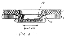
- Figure 6 shows a joint which may be formed by the method according to the invention.
- the deformation and displacement of the material in the direction of the die has further laterally extruded the material around the tip 7 of the punch-core 6 so that the inner sidewall of the joint only touches the punch in the annular zone designated 14. This means that the forces needed to extract the punch from the joint will be much smaller due to the lower friction between the wall and the punch. Additionally the grip between the sheet formed members is increased due to the increased lateral extrusion.
- an undesired annular pocket 15 is formed between the sheets around the joint. It has been shown that this pocket can be eliminated or almost eliminated by the method according to the invention.
- one set of punch, die and anvil will allow a certain range of total thickness or number of sheet layers of the processed sheet formed members, still giving a higher strength of the joint than what is achieved by means of other methods.
Landscapes
- Engineering & Computer Science (AREA)
- Mechanical Engineering (AREA)
- Lining Or Joining Of Plastics Or The Like (AREA)
- Shaping Metal By Deep-Drawing, Or The Like (AREA)
- Making Paper Articles (AREA)
- Road Paving Structures (AREA)
- Conveying And Assembling Of Building Elements In Situ (AREA)
- Forging (AREA)
- Pressure Welding/Diffusion-Bonding (AREA)
- Wrappers (AREA)
- Laminated Bodies (AREA)
- Moulds For Moulding Plastics Or The Like (AREA)
Applications Claiming Priority (3)
| Application Number | Priority Date | Filing Date | Title |
|---|---|---|---|
| SE19939301097A SE9301097D0 (sv) | 1993-03-31 | 1993-03-31 | A method for joining together two or several overlaying sheet formed members, an apparatus for carrying out said method and a joint resulting from said method |
| SE9301097 | 1993-03-31 | ||
| PCT/EP1994/001029 WO1994022613A1 (en) | 1993-03-31 | 1994-03-31 | A method for joining together two or several overlaying sheet formed members, an apparatus for carrying out said method and a joint resulting from said method |
Publications (2)
| Publication Number | Publication Date |
|---|---|
| EP0643633A1 EP0643633A1 (en) | 1995-03-22 |
| EP0643633B1 true EP0643633B1 (en) | 1997-12-29 |
Family
ID=20389446
Family Applications (1)
| Application Number | Title | Priority Date | Filing Date |
|---|---|---|---|
| EP94913111A Expired - Lifetime EP0643633B1 (en) | 1993-03-31 | 1994-03-31 | A method for joining together two or several overlaying sheet formed members, an apparatus for carrying out said method |
Country Status (16)
| Country | Link |
|---|---|
| US (1) | US6205640B1 (cs) |
| EP (1) | EP0643633B1 (cs) |
| JP (1) | JP3564132B2 (cs) |
| KR (1) | KR100306030B1 (cs) |
| CN (1) | CN1060977C (cs) |
| AT (1) | ATE161447T1 (cs) |
| AU (1) | AU683055B2 (cs) |
| BR (1) | BR9404797A (cs) |
| CA (1) | CA2136437A1 (cs) |
| CZ (1) | CZ286317B6 (cs) |
| DE (1) | DE69407520T2 (cs) |
| ES (1) | ES2114684T3 (cs) |
| FI (1) | FI945622A7 (cs) |
| PL (1) | PL174479B1 (cs) |
| SE (1) | SE9301097D0 (cs) |
| WO (1) | WO1994022613A1 (cs) |
Cited By (1)
| Publication number | Priority date | Publication date | Assignee | Title |
|---|---|---|---|---|
| DE10248551B3 (de) * | 2002-10-18 | 2004-05-27 | Audi Ag | Verfahren zur Herstellung einer punktuellen, mechanischen Dreiblech-Fügeverbindung und Vorrichtung zur Durchführung des Verfahrens |
Families Citing this family (33)
| Publication number | Priority date | Publication date | Assignee | Title |
|---|---|---|---|---|
| JPH10503427A (ja) * | 1994-07-22 | 1998-03-31 | ビーティーエム コーポレイション | 薄板材の結合装置、およびこの装置で成形された結合部 |
| GB2334474B (en) | 1999-05-19 | 2000-01-19 | Colin Maxwell Wade | Ductile material clinch joiner |
| DE19959585A1 (de) * | 1999-12-10 | 2001-06-13 | Mannesmann Sachs Ag | Kupplungsscheibe |
| US6345438B1 (en) * | 2000-06-08 | 2002-02-12 | Homac Manufacturing Company | Method for making bus and post electrical connector using locking pins |
| US7121047B2 (en) * | 2001-05-14 | 2006-10-17 | Stepfast, Ltd. | Flashing assembly |
| AU2002367924A1 (en) * | 2002-05-08 | 2003-11-11 | Hans Bergkvist | A method for mechanically joining two or more layers of sheet material |
| DE10245604A1 (de) * | 2002-09-30 | 2004-04-15 | Fraunhofer-Gesellschaft zur Förderung der angewandten Forschung e.V. | Verfahren und Vorrichtung zum dauerhaften Verbinden von einander überlappenden, plattenförmigen Bauteilen |
| US7155953B1 (en) | 2004-05-19 | 2007-01-02 | Nikkel Robert E | Anvil driving assembly |
| DE102005000023A1 (de) * | 2005-03-22 | 2006-09-28 | Hilti Ag | Durchzuganordnung und Verfahren dazu |
| USD557128S1 (en) | 2005-09-22 | 2007-12-11 | Btm Corporation | Button shape for clinch joint |
| CN100341639C (zh) * | 2005-11-30 | 2007-10-10 | 天津理工大学 | 加工快速连接结构的可分式模具 |
| US8491745B2 (en) * | 2007-02-03 | 2013-07-23 | The Boeing Company | Method and material efficient tooling for continuous compression molding |
| ES2365373T3 (es) * | 2007-02-13 | 2011-10-03 | Inventio Ag | Procedimiento para clinchar piezas metálicas gruesas y utilización de una herramienta de clinchado. |
| AU2008215090B2 (en) * | 2007-02-13 | 2013-01-10 | Inventio Ag | Method and tool for clinching thick sheet metal, and use of the tool |
| US7762034B2 (en) | 2008-09-26 | 2010-07-27 | Chicago Metallic Corporation | Rotary stitch for joining sheet metal stock |
| US8650730B2 (en) * | 2009-02-23 | 2014-02-18 | Btm Corporation | Clinching tool |
| EP2329905B1 (en) * | 2009-12-03 | 2012-05-30 | Helmholtz-Zentrum Geesthacht Zentrum für Material- und Küstenforschung GmbH | Method for joining metal and plastic workpieces |
| JP5937295B2 (ja) | 2010-04-12 | 2016-06-22 | シロキ工業株式会社 | 結合構造及びウインドレギュレータ |
| ES2663305T3 (es) | 2010-11-10 | 2018-04-11 | Henrob Limited | Método de remachado |
| JP5889547B2 (ja) * | 2011-05-18 | 2016-03-22 | 矢崎総業株式会社 | 金属接合体 |
| CN102284629A (zh) * | 2011-08-26 | 2011-12-21 | 苏州托克斯冲压设备有限公司 | 金属板件的冲压腰形点连接模具与冲压腰形点连接方法 |
| CN103084492A (zh) * | 2011-11-08 | 2013-05-08 | 北京世博金属制品有限公司 | 用于橱柜抽屉上的抽帮与调节机构的连接方式 |
| DE102012008179A1 (de) * | 2012-04-26 | 2013-10-31 | Tox Pressotechnik Gmbh & Co. Kg | Verbindungssystem und Verfahren zum Verbinden von wenigstens zwei Bauteillagen |
| CN102861828A (zh) * | 2012-10-19 | 2013-01-09 | 重庆大学 | 一种降低冲压变形连接点高度的方法 |
| JP5602960B1 (ja) * | 2014-01-16 | 2014-10-08 | 武延 本郷 | 接合治具、接合体の製造方法、及び、接合体 |
| US10328481B2 (en) | 2014-03-18 | 2019-06-25 | Btm Company Llc | Clinching punch and apparatus |
| DE102014211212A1 (de) * | 2014-06-12 | 2015-12-17 | Volkswagen Ag | Verfahren zur Herstellung einer Hybridplatine und hieraus hergestelltes Blechformteil |
| CN108883456B (zh) * | 2016-02-24 | 2019-09-24 | 日新制钢株式会社 | 成形件制造方法 |
| DE102017115296A1 (de) * | 2017-07-07 | 2019-01-10 | Welser Profile Austria Gmbh | Verfahren zur Herstellung eines Durchzugniets |
| JPWO2019131356A1 (ja) * | 2017-12-28 | 2020-12-24 | 株式会社Gsユアサ | 蓄電装置 |
| NL1043110B1 (en) * | 2018-12-24 | 2020-07-21 | Bosch Gmbh Robert | Process for manufacturing a laminate of stacked metal parts including a multi-layer blanking process step |
| CN111531045B (zh) * | 2020-04-06 | 2022-03-22 | 慈溪市汉德电器有限公司 | 一种金属件铆接工艺 |
| IT202000018163A1 (it) * | 2020-07-27 | 2022-01-27 | Claudio Cenci | Dispositivo per l’applicazione di etichette |
Family Cites Families (20)
| Publication number | Priority date | Publication date | Assignee | Title |
|---|---|---|---|---|
| US3387481A (en) * | 1964-12-11 | 1968-06-11 | Harvey Aluminum Inc | Process for the deformation of sheet material |
| US5267383A (en) * | 1980-09-08 | 1993-12-07 | Btm Corporation | Apparatus for joining sheet material |
| US5150513A (en) * | 1980-09-08 | 1992-09-29 | Btm Corporation | Apparatus for joining sheet material |
| US5208974A (en) * | 1980-09-08 | 1993-05-11 | Btm Corporation | Apparatus for attaching a fastener to sheet material |
| US5208973A (en) * | 1980-09-08 | 1993-05-11 | Btm Corporation | Apparatus for joining sheet material |
| US4531279A (en) * | 1982-08-23 | 1985-07-30 | Robertshaw Controls Company | Method of making a leakproof joint |
| DE8408795U1 (de) * | 1984-03-22 | 1985-07-18 | Walter Eckold GmbH & Co KG Vorrichtungs- und Gerätebau, 3424 St Andreasberg | Vorrichtung zum Verbinden eines Blechs mit einem perforierten Blech |
| AU572351B2 (en) * | 1984-10-11 | 1988-05-05 | Brake And Clutch Industries Australia Pty. Ltd. | Metal forming process and apparatus and product of same |
| US4825525A (en) * | 1986-08-29 | 1989-05-02 | Obrecht Robert E | Clinching tool |
| US4803767A (en) * | 1986-08-29 | 1989-02-14 | Lamb Robo | Clinching tool |
| JPS63192524A (ja) * | 1987-02-03 | 1988-08-09 | Sharp Corp | 金属板の接合装置 |
| SE8800407D0 (sv) * | 1988-02-05 | 1988-02-05 | Cerac Sa | A method for joining two or several overlaying sheet formed members together, metal or non-metal, and an apparatus for carrying out said method |
| US5051020A (en) * | 1989-11-13 | 1991-09-24 | Tech-Line Engineering Co. | Leak proof joint |
| US5528815A (en) * | 1990-04-03 | 1996-06-25 | Webb; Edward L. T. | Clinching tool for sheet metal joining |
| US5315743A (en) * | 1990-05-18 | 1994-05-31 | Tech-Line Engineering Co. | Apparatus for forming a clinch joint |
| IE61054B1 (en) * | 1990-06-01 | 1994-09-21 | Fairacre Ltd | Sheet metal joining apparatus |
| US5479687A (en) * | 1994-01-31 | 1996-01-02 | Btm Corporation | Apparatus for joining sheets of material |
| US5727302A (en) * | 1994-01-31 | 1998-03-17 | Btm Corporation | Die and punch for forming a joint and method of making the die |
| US5984563A (en) * | 1994-07-22 | 1999-11-16 | Btm Corporation | Apparatus for joining sheet material and joint formed therein |
| SE9502587D0 (sv) * | 1995-07-11 | 1995-07-11 | Attexor Equip | A tool for making joints between sheet-formed members |
-
1993
- 1993-03-31 SE SE19939301097A patent/SE9301097D0/xx unknown
-
1994
- 1994-03-31 AT AT94913111T patent/ATE161447T1/de not_active IP Right Cessation
- 1994-03-31 DE DE69407520T patent/DE69407520T2/de not_active Expired - Lifetime
- 1994-03-31 AU AU65388/94A patent/AU683055B2/en not_active Ceased
- 1994-03-31 CA CA002136437A patent/CA2136437A1/en not_active Abandoned
- 1994-03-31 EP EP94913111A patent/EP0643633B1/en not_active Expired - Lifetime
- 1994-03-31 WO PCT/EP1994/001029 patent/WO1994022613A1/en not_active Ceased
- 1994-03-31 US US08/736,788 patent/US6205640B1/en not_active Expired - Fee Related
- 1994-03-31 CZ CZ19943269A patent/CZ286317B6/cs not_active IP Right Cessation
- 1994-03-31 KR KR1019940704351A patent/KR100306030B1/ko not_active Expired - Lifetime
- 1994-03-31 BR BR9404797A patent/BR9404797A/pt not_active IP Right Cessation
- 1994-03-31 CN CN94190146A patent/CN1060977C/zh not_active Expired - Lifetime
- 1994-03-31 JP JP52168194A patent/JP3564132B2/ja not_active Expired - Fee Related
- 1994-03-31 ES ES94913111T patent/ES2114684T3/es not_active Expired - Lifetime
- 1994-03-31 PL PL94306415A patent/PL174479B1/pl not_active IP Right Cessation
- 1994-11-29 FI FI945622A patent/FI945622A7/fi not_active Application Discontinuation
Cited By (1)
| Publication number | Priority date | Publication date | Assignee | Title |
|---|---|---|---|---|
| DE10248551B3 (de) * | 2002-10-18 | 2004-05-27 | Audi Ag | Verfahren zur Herstellung einer punktuellen, mechanischen Dreiblech-Fügeverbindung und Vorrichtung zur Durchführung des Verfahrens |
Also Published As
| Publication number | Publication date |
|---|---|
| PL306415A1 (en) | 1995-04-03 |
| KR950701850A (ko) | 1995-05-17 |
| CZ286317B6 (cs) | 2000-03-15 |
| FI945622A0 (fi) | 1994-11-29 |
| DE69407520D1 (de) | 1998-02-05 |
| BR9404797A (pt) | 1999-06-15 |
| US6205640B1 (en) | 2001-03-27 |
| EP0643633A1 (en) | 1995-03-22 |
| FI945622A7 (fi) | 1994-11-29 |
| PL174479B1 (pl) | 1998-08-31 |
| SE9301097D0 (sv) | 1993-03-31 |
| CN1060977C (zh) | 2001-01-24 |
| ATE161447T1 (de) | 1998-01-15 |
| KR100306030B1 (ko) | 2002-02-19 |
| DE69407520T2 (de) | 1998-07-30 |
| JPH07507499A (ja) | 1995-08-24 |
| CZ326994A3 (en) | 1996-04-17 |
| CA2136437A1 (en) | 1994-10-13 |
| WO1994022613A1 (en) | 1994-10-13 |
| AU683055B2 (en) | 1997-10-30 |
| JP3564132B2 (ja) | 2004-09-08 |
| AU6538894A (en) | 1994-10-24 |
| CN1106192A (zh) | 1995-08-02 |
| ES2114684T3 (es) | 1998-06-01 |
Similar Documents
| Publication | Publication Date | Title |
|---|---|---|
| EP0643633B1 (en) | A method for joining together two or several overlaying sheet formed members, an apparatus for carrying out said method | |
| US5339509A (en) | Method for attachment of fastener to sheet material | |
| CA2334216C (en) | Method of forming a tubular member | |
| US8424351B2 (en) | Automated monitoring for clinching joints | |
| US5208973A (en) | Apparatus for joining sheet material | |
| US5208974A (en) | Apparatus for attaching a fastener to sheet material | |
| JPH11153114A (ja) | 切断可能なステムを有するブラインドリベットおよびこのブラインドリベットをセッティングするための装置 | |
| JP4526241B2 (ja) | ピールタイプ・ブラインドリベット | |
| GB2281527A (en) | Cold forming method and apparatus | |
| US4365495A (en) | Method of making a mandrel for a self plugging blind rivet | |
| JP7035695B2 (ja) | 接合装置および接合体の製造方法 | |
| US5651173A (en) | Method for doubly upsetting tubing flanges | |
| EP0638378B1 (en) | A method of making a mandrel of a blind rivet | |
| US3896621A (en) | Actuating unit | |
| JP2005512849A (ja) | 変形可能な管状プラスティック容器のヘッド部品を形成する成形型 | |
| US7284403B2 (en) | Apparatus and method for performing a hydroforming process | |
| US20050177993A1 (en) | Method for mechanically joining two or more layers of sheet material | |
| EP1228856A2 (en) | Powder compacting tool | |
| JPH0227058B2 (cs) | ||
| JPH10315058A (ja) | 壁に結合要素を取り付けるための方法および装置 | |
| US3952399A (en) | Uniting two elements | |
| JPH10216893A (ja) | 管材のフランジ加工装置及びその方法 | |
| JP3286647B2 (ja) | つば状部と曲面状部とを有する部材の製造方法 | |
| JPS5848264B2 (ja) | 底付中空金属製品の製造方法 | |
| JPH0729175B2 (ja) | 歯車素材の製造方法及びその装置 |
Legal Events
| Date | Code | Title | Description |
|---|---|---|---|
| PUAI | Public reference made under article 153(3) epc to a published international application that has entered the european phase |
Free format text: ORIGINAL CODE: 0009012 |
|
| 17P | Request for examination filed |
Effective date: 19941230 |
|
| AK | Designated contracting states |
Kind code of ref document: A1 Designated state(s): AT BE CH DE DK ES FR GB GR IE IT LI LU MC NL PT SE |
|
| 17Q | First examination report despatched |
Effective date: 19950427 |
|
| GRAG | Despatch of communication of intention to grant |
Free format text: ORIGINAL CODE: EPIDOS AGRA |
|
| GRAG | Despatch of communication of intention to grant |
Free format text: ORIGINAL CODE: EPIDOS AGRA |
|
| GRAG | Despatch of communication of intention to grant |
Free format text: ORIGINAL CODE: EPIDOS AGRA |
|
| GRAH | Despatch of communication of intention to grant a patent |
Free format text: ORIGINAL CODE: EPIDOS IGRA |
|
| GRAH | Despatch of communication of intention to grant a patent |
Free format text: ORIGINAL CODE: EPIDOS IGRA |
|
| GRAA | (expected) grant |
Free format text: ORIGINAL CODE: 0009210 |
|
| AK | Designated contracting states |
Kind code of ref document: B1 Designated state(s): AT BE CH DE DK ES FR GB GR IE IT LI LU MC NL PT SE |
|
| PG25 | Lapsed in a contracting state [announced via postgrant information from national office to epo] |
Ref country code: NL Free format text: LAPSE BECAUSE OF FAILURE TO SUBMIT A TRANSLATION OF THE DESCRIPTION OR TO PAY THE FEE WITHIN THE PRESCRIBED TIME-LIMIT Effective date: 19971229 Ref country code: GR Free format text: LAPSE BECAUSE OF FAILURE TO SUBMIT A TRANSLATION OF THE DESCRIPTION OR TO PAY THE FEE WITHIN THE PRESCRIBED TIME-LIMIT Effective date: 19971229 Ref country code: DK Free format text: LAPSE BECAUSE OF NON-PAYMENT OF DUE FEES Effective date: 19971229 Ref country code: BE Free format text: LAPSE BECAUSE OF FAILURE TO SUBMIT A TRANSLATION OF THE DESCRIPTION OR TO PAY THE FEE WITHIN THE PRESCRIBED TIME-LIMIT Effective date: 19971229 Ref country code: AT Free format text: LAPSE BECAUSE OF NON-PAYMENT OF DUE FEES Effective date: 19971229 |
|
| REF | Corresponds to: |
Ref document number: 161447 Country of ref document: AT Date of ref document: 19980115 Kind code of ref document: T |
|
| REG | Reference to a national code |
Ref country code: CH Ref legal event code: EP |
|
| REF | Corresponds to: |
Ref document number: 69407520 Country of ref document: DE Date of ref document: 19980205 |
|
| PGFP | Annual fee paid to national office [announced via postgrant information from national office to epo] |
Ref country code: DK Payment date: 19980311 Year of fee payment: 5 Ref country code: AT Payment date: 19980311 Year of fee payment: 5 |
|
| PGFP | Annual fee paid to national office [announced via postgrant information from national office to epo] |
Ref country code: NL Payment date: 19980326 Year of fee payment: 5 |
|
| ITF | It: translation for a ep patent filed | ||
| PGFP | Annual fee paid to national office [announced via postgrant information from national office to epo] |
Ref country code: IE Payment date: 19980327 Year of fee payment: 5 |
|
| PG25 | Lapsed in a contracting state [announced via postgrant information from national office to epo] |
Ref country code: PT Free format text: LAPSE BECAUSE OF FAILURE TO SUBMIT A TRANSLATION OF THE DESCRIPTION OR TO PAY THE FEE WITHIN THE PRESCRIBED TIME-LIMIT Effective date: 19980330 |
|
| PGFP | Annual fee paid to national office [announced via postgrant information from national office to epo] |
Ref country code: MC Payment date: 19980331 Year of fee payment: 5 |
|
| ET | Fr: translation filed | ||
| REG | Reference to a national code |
Ref country code: ES Ref legal event code: FG2A Ref document number: 2114684 Country of ref document: ES Kind code of ref document: T3 |
|
| NLV1 | Nl: lapsed or annulled due to failure to fulfill the requirements of art. 29p and 29m of the patents act | ||
| REG | Reference to a national code |
Ref country code: IE Ref legal event code: FG4D Free format text: 78072 |
|
| REG | Reference to a national code |
Ref country code: CH Ref legal event code: NV Representative=s name: PATECH S.A. |
|
| PLBE | No opposition filed within time limit |
Free format text: ORIGINAL CODE: 0009261 |
|
| STAA | Information on the status of an ep patent application or granted ep patent |
Free format text: STATUS: NO OPPOSITION FILED WITHIN TIME LIMIT |
|
| 26N | No opposition filed | ||
| PG25 | Lapsed in a contracting state [announced via postgrant information from national office to epo] |
Ref country code: LU Free format text: LAPSE BECAUSE OF NON-PAYMENT OF DUE FEES Effective date: 19990331 Ref country code: IE Free format text: LAPSE BECAUSE OF NON-PAYMENT OF DUE FEES Effective date: 19990331 |
|
| PG25 | Lapsed in a contracting state [announced via postgrant information from national office to epo] |
Ref country code: MC Free format text: LAPSE BECAUSE OF NON-PAYMENT OF DUE FEES Effective date: 19990930 |
|
| REG | Reference to a national code |
Ref country code: GB Ref legal event code: IF02 |
|
| PGFP | Annual fee paid to national office [announced via postgrant information from national office to epo] |
Ref country code: SE Payment date: 20020306 Year of fee payment: 9 |
|
| PG25 | Lapsed in a contracting state [announced via postgrant information from national office to epo] |
Ref country code: SE Free format text: LAPSE BECAUSE OF NON-PAYMENT OF DUE FEES Effective date: 20030401 |
|
| EUG | Se: european patent has lapsed | ||
| PGFP | Annual fee paid to national office [announced via postgrant information from national office to epo] |
Ref country code: GB Payment date: 20040407 Year of fee payment: 11 |
|
| PGFP | Annual fee paid to national office [announced via postgrant information from national office to epo] |
Ref country code: CH Payment date: 20040416 Year of fee payment: 11 |
|
| PG25 | Lapsed in a contracting state [announced via postgrant information from national office to epo] |
Ref country code: LI Free format text: LAPSE BECAUSE OF NON-PAYMENT OF DUE FEES Effective date: 20050331 Ref country code: GB Free format text: LAPSE BECAUSE OF NON-PAYMENT OF DUE FEES Effective date: 20050331 Ref country code: CH Free format text: LAPSE BECAUSE OF NON-PAYMENT OF DUE FEES Effective date: 20050331 |
|
| PGFP | Annual fee paid to national office [announced via postgrant information from national office to epo] |
Ref country code: FR Payment date: 20050930 Year of fee payment: 13 |
|
| REG | Reference to a national code |
Ref country code: CH Ref legal event code: PL |
|
| GBPC | Gb: european patent ceased through non-payment of renewal fee |
Effective date: 20050331 |
|
| PG25 | Lapsed in a contracting state [announced via postgrant information from national office to epo] |
Ref country code: FR Free format text: LAPSE BECAUSE OF NON-PAYMENT OF DUE FEES Effective date: 20051130 |
|
| REG | Reference to a national code |
Ref country code: FR Ref legal event code: ST Effective date: 20051130 |
|
| PGFP | Annual fee paid to national office [announced via postgrant information from national office to epo] |
Ref country code: IT Payment date: 20120326 Year of fee payment: 19 |
|
| PGFP | Annual fee paid to national office [announced via postgrant information from national office to epo] |
Ref country code: ES Payment date: 20130319 Year of fee payment: 20 Ref country code: DE Payment date: 20130322 Year of fee payment: 20 |
|
| REG | Reference to a national code |
Ref country code: DE Ref legal event code: R071 Ref document number: 69407520 Country of ref document: DE |
|
| REG | Reference to a national code |
Ref country code: DE Ref legal event code: R071 Ref document number: 69407520 Country of ref document: DE |
|
| PG25 | Lapsed in a contracting state [announced via postgrant information from national office to epo] |
Ref country code: DE Free format text: LAPSE BECAUSE OF EXPIRATION OF PROTECTION Effective date: 20140401 |
|
| REG | Reference to a national code |
Ref country code: ES Ref legal event code: FD2A Effective date: 20140926 |
|
| PG25 | Lapsed in a contracting state [announced via postgrant information from national office to epo] |
Ref country code: ES Free format text: LAPSE BECAUSE OF EXPIRATION OF PROTECTION Effective date: 20140401 |