EP0644281B1 - Procédé et dispositif pour la production d'un retors - Google Patents
Procédé et dispositif pour la production d'un retors Download PDFInfo
- Publication number
- EP0644281B1 EP0644281B1 EP94112095A EP94112095A EP0644281B1 EP 0644281 B1 EP0644281 B1 EP 0644281B1 EP 94112095 A EP94112095 A EP 94112095A EP 94112095 A EP94112095 A EP 94112095A EP 0644281 B1 EP0644281 B1 EP 0644281B1
- Authority
- EP
- European Patent Office
- Prior art keywords
- thread
- spinning
- fibre material
- balloon
- spindle
- Prior art date
- Legal status (The legal status is an assumption and is not a legal conclusion. Google has not performed a legal analysis and makes no representation as to the accuracy of the status listed.)
- Expired - Lifetime
Links
- 238000000034 method Methods 0.000 title claims description 23
- 238000009987 spinning Methods 0.000 claims description 71
- 239000000835 fiber Substances 0.000 claims description 30
- 239000000463 material Substances 0.000 claims description 18
- 238000004519 manufacturing process Methods 0.000 claims description 5
- 239000002657 fibrous material Substances 0.000 description 26
- 238000007383 open-end spinning Methods 0.000 description 7
- 238000004804 winding Methods 0.000 description 4
- 238000011161 development Methods 0.000 description 2
- 230000018109 developmental process Effects 0.000 description 2
- 238000003860 storage Methods 0.000 description 2
- 238000006243 chemical reaction Methods 0.000 description 1
- 230000001143 conditioned effect Effects 0.000 description 1
- 230000001419 dependent effect Effects 0.000 description 1
- 230000000694 effects Effects 0.000 description 1
- 238000005516 engineering process Methods 0.000 description 1
- 238000010040 friction spinning Methods 0.000 description 1
- 238000007378 ring spinning Methods 0.000 description 1
- 238000011144 upstream manufacturing Methods 0.000 description 1
Images


Classifications
-
- D—TEXTILES; PAPER
- D01—NATURAL OR MAN-MADE THREADS OR FIBRES; SPINNING
- D01H—SPINNING OR TWISTING
- D01H4/00—Open-end spinning machines or arrangements for imparting twist to independently moving fibres separated from slivers; Piecing arrangements therefor; Covering endless core threads with fibres by open-end spinning techniques
- D01H4/04—Open-end spinning machines or arrangements for imparting twist to independently moving fibres separated from slivers; Piecing arrangements therefor; Covering endless core threads with fibres by open-end spinning techniques imparting twist by contact of fibres with a running surface
-
- D—TEXTILES; PAPER
- D01—NATURAL OR MAN-MADE THREADS OR FIBRES; SPINNING
- D01H—SPINNING OR TWISTING
- D01H1/00—Spinning or twisting machines in which the product is wound-up continuously
-
- D—TEXTILES; PAPER
- D01—NATURAL OR MAN-MADE THREADS OR FIBRES; SPINNING
- D01H—SPINNING OR TWISTING
- D01H7/00—Spinning or twisting arrangements
- D01H7/02—Spinning or twisting arrangements for imparting permanent twist
- D01H7/90—Arrangements with two or more spinning or twisting devices of different types in combination
Definitions
- the most common way of producing a twine is that in a first stage of work using suitable spinning units, e.g. Rotor spinning or friction spinning devices are made from dissolved fiber material or ring spinning devices, which are spun in a subsequent work step by means of twisting devices, e.g. Double wire twisting devices to be processed into a twine.
- suitable spinning units e.g. Rotor spinning or friction spinning devices are made from dissolved fiber material or ring spinning devices, which are spun in a subsequent work step by means of twisting devices, e.g. Double wire twisting devices to be processed into a twine.
- twisting devices e.g. Double wire twisting devices to be processed into a twine.
- independent spinning machines acting on the one hand and threading machines on the other hand are required, which is complex both in terms of machine and in terms of the workflow.
- the invention is concerned in advance with the idea of creating a method for producing a thread in an integrated spinning-twisting process, which works on the double-wire principle.
- thread balloon An essential element in the double wire twisting process is the thread balloon, in which the thread forms an envelope around the stationary bobbin of the thread spindle, which was previously regarded as impenetrable in order to allow material flows, e.g. also fiber material to feed into the space enclosed by the thread balloon.
- DE-OS 1 785 366 dating from 1972, deals with a spinning process, which at this time is still referred to as "element spinning", in which fiber material is arranged into a fiber band, which is brought into the form of a rotating balloon, in which is given to the sliver at least two turns per revolution of the balloon and the resulting yarn is drawn off.
- the device for carrying out this known spinning process has a spinning chamber which is arranged on a spindle and into which the fiber material is introduced through a fiber inlet tube which runs coaxially to the spindle axis and a channel which runs radially through the spindle rotor. Inside the spinning chamber there is a collecting ring for the fiber material, which is formed into a fuse there.
- the stretched fiber sliver is guided through a channel lying in the spindle axis, in which it receives a first rotation and from which it emerges in the radial direction and enters a rotating balloon surrounding the spinning chamber, in which it receives the second rotation.
- the thread drawn off from the spinning rotor is returned to the common axis of the spinning rotor and the double-wire rotor by a draw-off channel arranged in the double-wire rotor and running in an arc around the outside of the spinning rotor, and is discharged upwards through the drive device of the double-wire rotor.
- a second turn is applied to the thread.
- the fiber material is fed to the spinning rotor through a feed channel in the double-wire rotor, the receiving opening of which is symmetrical and the discharge opening of which is eccentric to the axis of the double-wire rotor.
- the invention has for its object to provide a method for producing a thread from at least two yarn components, in which only twisted fiber material is fed to the twisting spindle and the finished twisted thread is withdrawn from the spindle.
- the basic idea of the invention in particular in terms of the design of the device, is to use the fiber material introduced into the twisting spindle through the rotating thread balloon directly for the production of a twist from at least two spun threads and this fiber material so that it does not disturb the balloon on the one hand and on the other hand there is enough space to accommodate several spinning units within the space defined by the thread balloon, to which the fiber material is fed in separate streams, while the spinning threads drawn off by the spinning devices together through the hollow spindle axis and Thread balloon are guided.
- the space previously occupied by the necessary supply spools is available to the spinning units and their drive mechanism.
- the spinning and twisting technology process in the open-end spinning-twisting system according to the invention is as follows:
- Dissolved fiber material is preferably fed through the thread balloon to the interior of the spindle just above or in the preferably upper region of a thread guide element that rotates with the thread balloon - balloon limiter or thread guide tube.
- the thread is preferably guided through a thread guide element attached to the rotating thread guide element.
- Each fiber stream supplies a spinning unit, for example a spinning rotor.
- the spinning rotors are driven by an electric motor in the opposite direction to the direction of rotation of the double-twisted spindle.
- a spinning thread is pulled up from each spinning rotor and fed to the spindle center, that is to say the hollow axis of the double-wire twisting spindle.
- the trade association is created, which is directly followed by the first twisting zone of the double-wire twisting spindle connects.
- the thread is then conveyed radially outwards through the usual thread guide channel and deflected upwards along the thread guide element which also rotates with the spindle rotor, whereby it is guided in the area of the fiber feed or fiber feed through the thread guide element which also rotates before it is in the extension of the hollow spindle axis Centering point, for example a balloon thread guide eyelet, passes through.
- a positively driven take-off unit which is fixed to the frame and which is followed by a conventional thread winding unit. Between the take-off unit and the take-up unit, a conventional thread length compensation unit is arranged, which has a certain thread storage function.
- the feeding or feeding of the dissolved fiber material to or into the spinning units is preferably carried out by means of negative pressure, which is built up in the area of the spinning units by a suction pipe running in the area of the spindle axis, which is connected at its outer end to a suction source, while to the Connect the inner end of this suction tube air channels, which are guided so that they are able to build up a negative pressure gradient in the direction of the fiber feed, causing the fiber feed to the spinning units, in the fiber material feed tubes of the spinning units.
- FIG. 1 shows a schematic representation of the process sequence of the open-end spinning-twisting method according to the invention within a space of a double-wire twisting spindle enclosed by a thread balloon.
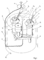
- FIG. 2 shows, partly in section, a perspective view of a double-wire twisting spindle with an upstream fiber-dissolving unit and a downstream thread winding unit.
- FIG. 3 shows a sectional view of a double-wire twisting spindle with integrated spinning units in the form of spinning rotors.
- the schematic representation according to FIG. 1 shows two rotor spinning devices R1 and R2 which are arranged directly adjacent to one another and driven by a motor M, and which have fiber material dissolved in the direction of arrows f1 and f2 through fiber material supply tubes 3 and 4 and directly in the spinning rotors 1 and 2 outgoing fiber material feed pipes 5 and 6 are supplied.
- the spun threads F1 and F2 produced within the spinning rotors 1 and 2 according to the usual open-end process are drawn upwards from the spinning rotors 1 and 2 open at the top and brought together at a union point P, from where they form a twine in accordance with the double-wire principle F3 can be combined by axially along the axial wire in the usual way through the double-wire twisting spindle shown schematically in FIG.
- the spindle axis is withdrawn and, after exiting the radial thread storage channel, forming a thread balloon up to the centering point defined in the extension of the spindle hollow axis, defined by the two roller bodies a and b , and from there it is carried on in the usual way to a thread winding unit.
- the spinning rotors 1 and 2 rotate in the same direction in one direction of rotation, while the spindle rotor, not shown, of the double-wire twisting spindle in the direction of the arrow f5 opposite to the two spinning rotors circulates.
- the thread or thread f3 is passed through a thread guide element 8 attached to the upper edge of the balloon limiter 7, which in the gap between the outer feed tubes 3, 4 and in the Spinning rotors, barrel material feed pipes 5, 6 protrude.
- the two spinning rotors 1 and 2 of the rotor spinning devices R1 and R2 are driven by the motor M by means of a drive belt 9.
- FIG. 2 shows an outer housing 10 which surrounds a double-wire twisting spindle, which is represented essentially by the balloon limiter 7, the upper inlet opening of the spindle hollow axis 11 and the thread travel path schematically represented by the arrows f6, f7 and f8.
- a chamber 12 is arranged within the space defined by the balloon limiter 7, in which one (R2) of the two rotor spinning devices indicated in FIG. 1 is housed.
- the fiber material feed pipe 6 opens into the spinning rotor 2, the outer fiber material feed opening of which lies in a cover 12.3 of the chamber 12.
- This feed opening is at a distance from the opening of the fiber material introduction tube 4 which is guided through the outer housing 10 and which forms part of a fiber material dissolving unit 14 to which a fiber band FB is fed from a can 20 for the rotor spinning device R1 (not shown in FIG. 2) the same fiber material dissolving unit 15 is provided.
- the two spinning threads drawn off from the spinning rotors 1 and 2 are combined with one another in the region of the upper inlet opening 11a of the hollow spindle axis 11, they pass through the hollow spindle axis in the direction of the arrow f6 downward, and are then drawn off radially outward in the direction of the arrow f7 before they are drawn off essentially upwards in the direction of arrow f8 along the inner surface of the balloon limiter 7 and are guided to a delivery mechanism 16, 17 through a thread outlet opening located coaxially to the spindle hollow axis on the upper side of the outer housing 10. Behind this delivery mechanism 16, 17, the finished twisting thread becomes a common thread via two deflection rollers 18, 19, of which at least one is pivotably mounted to form a thread length compensation mechanism against spring force. Traversing thread guide winding unit B continued.
- a hollow shaft 23 is rotatably mounted in a machine frame represented by a spindle bench 21 by means of a bearing block 22, whose outer, that is, the lower end, can be connected to a suction air source, not shown.
- a balloon limiter 7 is attached to the outer circumference of the spindle rotor disk 26 as a thread guide element for the thread F3 which carries a thread guide member 28 at its upper end.
- the spindle rotor is thus essentially formed by the following elements: hollow shaft 23, spindle rotor disk 26, balloon limiter 7, thread guide member 28 and thread guide tube 29.
- the essentially closed, rotation-proof chamber 12 On the upper end of the hollow shaft 23, with the interposition of suitable bearings, the essentially closed, rotation-proof chamber 12 is mounted, which preferably has the shape of a cylinder and comprises a bottom 12.1, an outer wall 12.2 and a removable cover 12.3.
- the two rotor spinning devices R1 and R2 are accommodated in this chamber 12, the spinning rotors 1 and 2 of which are driven by the motor M (not shown in FIG. 3) by means of the drive belt 9.
- the cover 12.3 Through the cover 12.3, the fiber material feed pipes 5 and 6 shown schematically in particular in FIGS. 1 and 2 open into the spinning rotors 1 and 2.
- thread take-off tubes 31 and 32 which run coaxially above the spinning rotor axes, through which the spinning threads F1 and F2 produced in the spinning rotors 1 and 2 are drawn off, before they enter through the upper inlet end 11a of the downwardly directed hollow spindle axis 11, which, for example, interposes one Annular gap seal 33 opens into the upper end of the thread guide tube 29.
- the hollow shaft 23 At the inner end of the hollow shaft 23 there are air channels 39, 40 which open into the interior of the chamber 12 in the area of the spinning rotors 1 and 2.
- the outer end of the hollow shaft 23 is connected in a manner not shown to a suction source, so that a vacuum is generated in the interior of the chamber 12 via the hollow shaft 23 and the air channels 39, 40, which acts in the fiber material feed pipes 5 and 6 and fiber feed to the spinning rotors 1 and 2.
- the spinning and twisting unit described so far in connection with FIG. 3 is surrounded by an outer housing 34 which carries a removable cover 35 into which, for example, holding magnets N are inserted, which cooperate with counter magnets S inserted in the cover 12.3 of the chamber 12 in order to achieve the To hold chamber 12 and thus the rotor spinning devices R1 and R2 as a non-contact holding device against rotation about the spindle axis.
- the motor M is supplied with energy through the spindle rotor disk 26 via a slip ring contact system 41, 42, 43 and 44, which is indicated schematically in FIG. 3, and corresponding electrical line connections. Dynamometric energy conversion can also be used to generate and supply the necessary electrical energy.
- the thread guide element which is shown in particular in FIGS. 2 and 3 in the form of a balloon limiter 7, can also have the shape of a thread guide tube adjoining the thread guide channel 27 and optionally guided up to the upper centering point, that is to say the thread outlet opening 37, the thread guide element shown in FIG. 3 then 28 can form part of this thread guide tube.
- the thread guide tube can also end at the level of the thread guide tube 28, with the upper end of this thread guide tube then taking over the function of the thread guide gate 28 which is otherwise present.
Landscapes
- Engineering & Computer Science (AREA)
- Mechanical Engineering (AREA)
- Textile Engineering (AREA)
- Spinning Or Twisting Of Yarns (AREA)
Claims (10)
- Procédé de fabrication d'un fil retors dans un processus de retordage à broche intégré, dans lequel au moyen d'au moins deux groupes de filage (R1, R2) disposés l'un à côté de l'autre, on produit des fils filables individuels à partir d'un matériau fibreux, ces fils filables étant groupés et soumis en continu, dans une première direction de passage de fil, conjointement à une rotation de retordage, caractérisé par le fait que les fils filables (F1, F2) sont ensuite guidés dans une deuxième direction de passage de fil, opposée à la première direction de passage de fil, et forment alors un ballon de fil tournant autour du groupe de filage, ballon qu'ils traversent et dans lequel ils sont soumis - de manière correspondante au principe de la double torsion - à la deuxième rotation de retordage, pour enfin être extraits en passant par un centre (37) situé dans le prolongement de l'axe du ballon de fil et qu'à chaque groupe de filage (R1, R2) est amené, en passant à travers la surface d'enveloppe définie par le ballon de fil, du matériau fibreux désagrégé.
- Procédé selon la revendication 1, caractérisé par le fait que le matériau fibreux est amené au groupe de filage (R1, R2) sensiblement de côté, ou radialement.
- Procédé selon l'une des revendications 1 et 2, caractérisé par le fait que l'amenée du matériau fibreux s'effectue sous l'action d'un gradient de pression qui est négatif dans la direction de l'amenée de fibres.
- Procédé selon la revendication 3, caractérisé par le fait que l'amenée du matériau fibreux s'effectue au moyen d'une dépression.
- Dispositif de mise en oeuvre du procédé selon la revendication 1, comportant au moins un rotor de broche pouvant être entraîné et tourillonnant dans un bâti machine (21) et un axe creux de broche (11, 29) auquel se raccorde un canal de guidage de fil (27) destiné à un fil et évoluant sensiblement radialement vers l'extérieur, fil qui, après être sorti du canal de guidage de fil (27) continue à être guidé avec la formation d'un ballon vers un centre (37) situé dans le prolongement de l'axe creux de broche (11, 29) puis continue à être guidé vers un groupe d'enroulement de fil (B) et avec un dispositif destiné à assurer l'amenée d'un matériau fibreux désagrégé, dans l'espace défini par le ballon de fil, caractérisé par le fait que, à l'intérieur de l'espace défini par le ballon de fil, sont disposés au moins deux groupes de filage (R1, R2) ayant chacun des tubes d'introduction de matériau fibreux (5, 6) associés, tubes dont les ouvertures d'introduction extérieures du matériau fibreux sont situées à l'extérieur de l'espace défini par le ballon de fil, des tubes d'amenée de matériau fibreux (3, 4) faisant partie de groupes de désagrégation (14, 15) de matériau fibreux, qu'aux groupes de filage sont associés des tubes d'évacuation de fil (31, 32), de manière que les fils filables (F1, F2), produits au moyen des groupes de filage, puissent être introduits conjointement et centralement dans l'axe creux de broche (11, 29) et que, sur le rotor de broche, est disposé à demeure un élément de guidage de fil (17) se raccordant à l'ouverture de sortie du canal de guidage de fil (27).
- Dispositif selon la revendication 5, caractérisé par le fait qu'à titre de partie de l'élément de guidage de fil (7) tournant avec le rotor de broche est prévu un organe de guidage de fil (8) qui pénètre dans l'intervalle existant entre les ouvertures d'introduction de matériau fibreux extérieures des tubes d'introduction de matériau fibreux (5, 6) et les ouvertures d'embouchure opposées des tubes d'amenée de matériau fibreux (3, 4).
- Dispositif selon la revendication 5 ou 6, caractérisé par le fait que le rotor de broche comprend un arbre creux (23) susceptible d'être raccordé à son extrémité extérieure à une conduite d'air, arbre creux sur lequel est montée une chambre (12) bloquée contre toute rotation et sensiblement fermée, chambre recevant les groupes de filage (R1, R2) et leurs mécanismes d'entraînement (M) et contenant des canaux d'air (39, 40) se raccordant à l'extrémité intérieure de l'arbre creux (23) et guidés de manière qu'ils permettent d'établir dans les tubes d'injection de matériau fibreux (5, 6) guidés à travers les sections de paroi de la chambre (12) et appartenant aux groupes de filage (R1, R2) un gradient de pression négatif, provoquant l'injection des fibres dans les groupes de filage.
- Dispositif selon la revendication 7, caractérisé par le fait que la chambre (12) présente un couvercle (12.3) amovible.
- Dispositif selon la revendication 5, caractérisé par un carter extérieur (34, 35) sensiblement fermé, stationnaire, entourant la chambre (12) et sur la face supérieure duquel est disposé, coaxialement par rapport à l'axe creux de broche, le centre qui se présente sous la forme d'une ouverture de sortie de fil (37) et dans la paroi latérale duquel sont disposées les ouvertures d'embouchure des tubes d'amenée de matériau fibreux (3, 4).
- Dispositif selon la revendication 9, caractérisé par le fait que le carter (34) a un couvercle (35) amovible.
Applications Claiming Priority (3)
| Application Number | Priority Date | Filing Date | Title |
|---|---|---|---|
| DE4331801 | 1993-09-18 | ||
| DE4331801A DE4331801C1 (de) | 1993-09-18 | 1993-09-18 | Verfahren und Vorrichtung zur Herstellung eines Zwirns in einem integrierten Spinn-Zwirnprozeß |
| US08/310,695 US5479771A (en) | 1993-09-18 | 1994-09-16 | Method and device for manufacturing a twisted yarn |
Publications (3)
| Publication Number | Publication Date |
|---|---|
| EP0644281A2 EP0644281A2 (fr) | 1995-03-22 |
| EP0644281A3 EP0644281A3 (fr) | 1995-07-19 |
| EP0644281B1 true EP0644281B1 (fr) | 1997-05-21 |
Family
ID=25929683
Family Applications (1)
| Application Number | Title | Priority Date | Filing Date |
|---|---|---|---|
| EP94112095A Expired - Lifetime EP0644281B1 (fr) | 1993-09-18 | 1994-08-03 | Procédé et dispositif pour la production d'un retors |
Country Status (6)
| Country | Link |
|---|---|
| US (1) | US5479771A (fr) |
| EP (1) | EP0644281B1 (fr) |
| JP (1) | JPH07150426A (fr) |
| CN (1) | CN1109523A (fr) |
| CZ (1) | CZ287433B6 (fr) |
| DE (1) | DE4331801C1 (fr) |
Families Citing this family (21)
| Publication number | Priority date | Publication date | Assignee | Title |
|---|---|---|---|---|
| DE4427876C1 (de) * | 1994-08-06 | 1995-09-28 | Palitex Project Co Gmbh | Vorrichtung zur Herstellung eines Zwirns |
| DE4427875C1 (de) * | 1994-08-06 | 1996-01-04 | Palitex Project Co Gmbh | Verfahren zur Herstellung eines Zwirns in einem integrierten Spinn-Zwirnprozess nach dem Doppeldrahtprinzip sowie Vorrichtung zur Durchführung des Verfahrens |
| DE4430917C1 (de) * | 1994-08-31 | 1995-09-28 | Palitex Project Co Gmbh | Verfahren und Vorrichtung zur Herstellung eines Zwirns |
| DE4431830C1 (de) | 1994-09-07 | 1995-10-26 | Palitex Project Co Gmbh | Verfahren zum Anspinnen eines Fadens in einer Vorrichtung zur Herstellung eines Zwirns in einem integrierten Spinn-Zwirnprozeß sowie Vorrichtung zur Durchführung des Verfahrens |
| EP0867541B1 (fr) * | 1997-03-15 | 2000-03-01 | Volkmann GmbH & Co. | Procédé pour fabriquer un fil retors dans un processus combiné de filature et retordage |
| DE19727176C1 (de) * | 1997-06-26 | 1998-11-12 | Volkmann Gmbh & Co | Verfahren zur kontinuierlichen Herstellung eines Zwirnes mit geringer Kringelneigung |
| DE19735651C1 (de) * | 1997-08-16 | 1998-08-20 | Volkmann Gmbh | Verfahren zur berührungslosen Energie- und Signalübertragung an Textilmaschinen, insbesondere Zwirnmaschinen sowie Einrichtung zur Durchführung des Verfahrens |
| DE19739282A1 (de) * | 1997-09-08 | 1999-03-11 | Volkmann Gmbh & Co | Vorrichtung zur Herstellung eines Zwirns in einem kombinierten Spinn-Zwirnprozeß |
| DE19807981C1 (de) * | 1998-02-25 | 1999-05-06 | Volkmann Gmbh & Co | Verfahren zur Herstellung eines Zwirns in einem integrierten Spinn-Zwirnprozeß nach dem Doppeldrahtprinzip sowie Vorrichtung zur Durchführung des Verfahrens |
| EP1026293A1 (fr) * | 1999-02-06 | 2000-08-09 | Volkmann GmbH & Co. | Tuyeau d'alimentation en fibres pour matériau de fibres ouvert |
| DE19905184C1 (de) * | 1999-02-09 | 2000-03-16 | Volkmann Gmbh & Co | Vorrichtung zur Herstellung eines Zwirns in einem integrierten Spinn-Zwirnprozeß |
| EP1045051A1 (fr) * | 1999-02-06 | 2000-10-18 | Volkmann GmbH | Dispositif pour la production d'un retors dans un processus de filature et de torsion combinés et un canal d'alimentation des fibres pour ce dispositif |
| DE19930284A1 (de) | 1999-07-01 | 2001-01-18 | Bosch Gmbh Robert | Kraftstofförderaggregat für eine Verbrennungskraftmaschine |
| DE10021160C1 (de) * | 2000-04-29 | 2001-05-17 | Volkmann Gmbh | Verfahren und Einrichtung zum Anspinnen der freien Enden von zwei Spinnfäden eines aus diesen Spinnfäden gebildeten Zwirnfadens im Rahmen eines integrierten OE-Spinn- und Doppeldrahtzwirn-Prozesses |
| DE10058723C1 (de) * | 2000-11-25 | 2002-01-10 | Volkmann Gmbh | Vorrichtung zur Herstellung eines Zwirns in einen integrierten Spinn-Zwirnprozeß |
| CN101429693B (zh) * | 2008-12-12 | 2011-12-28 | 宜昌经纬纺机有限公司 | 一种三股丝直接加捻成线的方法及捻线装置 |
| CN101824704B (zh) * | 2009-03-30 | 2011-07-27 | 张家港市维达纺织机械有限公司 | 钩编机的喂纱装置 |
| DE102010033666A1 (de) * | 2010-08-06 | 2012-02-09 | Rheinisch-Westfälische Technische Hochschule Aachen | Verfahren und Vorrichtung zur Herstellung eines Fasergarns |
| CN105019078A (zh) * | 2014-04-25 | 2015-11-04 | 苏州科技学院相城研究院 | 一步法纺制带压线的冰岛纱 |
| CN107475847A (zh) * | 2017-09-27 | 2017-12-15 | 浙江美来亚纺织有限公司 | 一种双头绒线输入回转头装置 |
| LU506057B1 (de) * | 2024-01-09 | 2025-07-09 | Saurer Spinning Solutions Gmbh & Co Kg | Spinnmaschine mit Kannensystem, Kannensystem |
Family Cites Families (5)
| Publication number | Priority date | Publication date | Assignee | Title |
|---|---|---|---|---|
| DE78710C (de) * | BADISCHE ANILIN- UND SODAFABRIK, Ludwigshafen a. Rh | Verfahren zur Darstellung beizenfärbender blauer Farbstoffe aus Nitrosodialkylm-amidophenol | ||
| US3439486A (en) * | 1967-09-15 | 1969-04-22 | Deering Milliken Res Corp | Spinning |
| BR7703747A (pt) * | 1976-06-09 | 1978-04-18 | Palitex Project Co Gmbh | Processo e dispositivo para o preparo de mechas de fibras texteis |
| DE3721364A1 (de) * | 1987-06-29 | 1989-01-19 | Palitex Project Co Gmbh | Spindelrotor als teil einer vorrichtung zum herstellen eines garnes oder zwirnes und mit einem solchen spingelrotor ausgeruestete doppeldraht-zwirnspindel |
| DE4023397A1 (de) * | 1990-07-23 | 1992-01-30 | Ssm Ag | Verfahren zum spinnen von fasern zu garn sowie spinnvorrichtung zur durchfuehrung des verfahrens |
-
1993
- 1993-09-18 DE DE4331801A patent/DE4331801C1/de not_active Expired - Fee Related
-
1994
- 1994-08-03 EP EP94112095A patent/EP0644281B1/fr not_active Expired - Lifetime
- 1994-09-16 US US08/310,695 patent/US5479771A/en not_active Expired - Fee Related
- 1994-09-16 CZ CZ19942279A patent/CZ287433B6/cs not_active IP Right Cessation
- 1994-09-16 CN CN94115343.6A patent/CN1109523A/zh active Pending
- 1994-09-19 JP JP6223324A patent/JPH07150426A/ja active Pending
Also Published As
| Publication number | Publication date |
|---|---|
| EP0644281A2 (fr) | 1995-03-22 |
| DE4331801C1 (de) | 1995-02-23 |
| CZ287433B6 (en) | 2000-11-15 |
| CZ227994A3 (en) | 1995-04-12 |
| JPH07150426A (ja) | 1995-06-13 |
| EP0644281A3 (fr) | 1995-07-19 |
| US5479771A (en) | 1996-01-02 |
| CN1109523A (zh) | 1995-10-04 |
Similar Documents
| Publication | Publication Date | Title |
|---|---|---|
| EP0644281B1 (fr) | Procédé et dispositif pour la production d'un retors | |
| CH678635A5 (fr) | ||
| EP2733241A1 (fr) | Dispositif de filage deux pour un | |
| EP1101847B1 (fr) | Cableuse et broche à retordre à double torsion avec dispositif d'enfilage pneumatique | |
| EP0701014B1 (fr) | Procédé pour rattacher un fil dans un dispositif pour fabriquer un retors dans un processus filature, torsion ainsi que dispositif pour réaliser le procédé | |
| EP0696656B1 (fr) | Procédé et dispositif pour fabriquer un retors | |
| DE4336109C2 (de) | Verfahren und Vorrichtung zur Herstellung eines Zwirns | |
| EP0616057B1 (fr) | Broche pour la production d'un fil textile | |
| EP0697476B1 (fr) | Procédé pour fabriquer un retors dans un processus filature-torsion d'après le principle à double torsion ainsi que dispositif pour réaliser le processus | |
| DE2364230B2 (de) | Verfahren und vorrichtung zur herstellung von kerngarn in einer offen-end- spinnvorrichtung | |
| EP0939152B1 (fr) | Procédé pour fabriquer un retors dans un processus filature-torsion d'après le principle à double torsion ainsi que dispositif pour réaliser le processus | |
| DE3025470C2 (de) | Offenend-Spinnvorrichtung | |
| EP1225258A1 (fr) | Procédé pour fabriquer des filés de fibres | |
| DE4427876C1 (de) | Vorrichtung zur Herstellung eines Zwirns | |
| EP0926275A2 (fr) | Métier à filer à bout ouvert pour fabriquer des fils à torsion S ou Z | |
| DE3246960A1 (de) | Verfahren und vorrichtung zum spinnen eines faserbuendelgarnes | |
| DE4430917C1 (de) | Verfahren und Vorrichtung zur Herstellung eines Zwirns | |
| DE19905184C1 (de) | Vorrichtung zur Herstellung eines Zwirns in einem integrierten Spinn-Zwirnprozeß | |
| DE2804542B1 (de) | Verfahren und Vorrichtung zum Herstellen eines Umwindegarnes | |
| DE10058723C1 (de) | Vorrichtung zur Herstellung eines Zwirns in einen integrierten Spinn-Zwirnprozeß | |
| EP1149938A2 (fr) | Procédé et dispositif pour rattacher deux bouts de fils duquels on fabriques un retors dans un processus filature à bout ouvert, torsion d'après le principle à double torsion | |
| DE4331802A1 (de) | Verfahren und Vorrichtung zur Herstellung eines Zwirns | |
| EP0468191A1 (fr) | Procédé pour le filage de fils à partir de fibres, et dispositif pour la mise en oeuvre du procédé | |
| EP0867541B1 (fr) | Procédé pour fabriquer un fil retors dans un processus combiné de filature et retordage | |
| DE69120519T2 (de) | Verfahren zum kontinuierlichen Spinne von Stapelfasern und Vorrichtung zur Durchführ des Verfahrens |
Legal Events
| Date | Code | Title | Description |
|---|---|---|---|
| PUAI | Public reference made under article 153(3) epc to a published international application that has entered the european phase |
Free format text: ORIGINAL CODE: 0009012 |
|
| AK | Designated contracting states |
Kind code of ref document: A2 Designated state(s): CH DE FR GB IT LI |
|
| PUAL | Search report despatched |
Free format text: ORIGINAL CODE: 0009013 |
|
| AK | Designated contracting states |
Kind code of ref document: A3 Designated state(s): CH DE FR GB IT LI |
|
| 17P | Request for examination filed |
Effective date: 19960113 |
|
| 17Q | First examination report despatched |
Effective date: 19960301 |
|
| GRAG | Despatch of communication of intention to grant |
Free format text: ORIGINAL CODE: EPIDOS AGRA |
|
| GRAH | Despatch of communication of intention to grant a patent |
Free format text: ORIGINAL CODE: EPIDOS IGRA |
|
| GRAH | Despatch of communication of intention to grant a patent |
Free format text: ORIGINAL CODE: EPIDOS IGRA |
|
| GRAA | (expected) grant |
Free format text: ORIGINAL CODE: 0009210 |
|
| AK | Designated contracting states |
Kind code of ref document: B1 Designated state(s): CH FR GB IT LI |
|
| ITF | It: translation for a ep patent filed | ||
| REG | Reference to a national code |
Ref country code: CH Ref legal event code: NV Representative=s name: A. BRAUN, BRAUN, HERITIER, ESCHMANN AG PATENTANWAE Ref country code: CH Ref legal event code: EP |
|
| GBT | Gb: translation of ep patent filed (gb section 77(6)(a)/1977) |
Effective date: 19970522 |
|
| ET | Fr: translation filed | ||
| PLBE | No opposition filed within time limit |
Free format text: ORIGINAL CODE: 0009261 |
|
| STAA | Information on the status of an ep patent application or granted ep patent |
Free format text: STATUS: NO OPPOSITION FILED WITHIN TIME LIMIT |
|
| 26N | No opposition filed | ||
| PGFP | Annual fee paid to national office [announced via postgrant information from national office to epo] |
Ref country code: GB Payment date: 20010725 Year of fee payment: 8 |
|
| PGFP | Annual fee paid to national office [announced via postgrant information from national office to epo] |
Ref country code: FR Payment date: 20010820 Year of fee payment: 8 |
|
| PGFP | Annual fee paid to national office [announced via postgrant information from national office to epo] |
Ref country code: CH Payment date: 20010904 Year of fee payment: 8 |
|
| REG | Reference to a national code |
Ref country code: GB Ref legal event code: IF02 |
|
| PG25 | Lapsed in a contracting state [announced via postgrant information from national office to epo] |
Ref country code: GB Free format text: LAPSE BECAUSE OF NON-PAYMENT OF DUE FEES Effective date: 20020803 |
|
| PG25 | Lapsed in a contracting state [announced via postgrant information from national office to epo] |
Ref country code: LI Free format text: LAPSE BECAUSE OF NON-PAYMENT OF DUE FEES Effective date: 20020831 Ref country code: CH Free format text: LAPSE BECAUSE OF NON-PAYMENT OF DUE FEES Effective date: 20020831 |
|
| GBPC | Gb: european patent ceased through non-payment of renewal fee |
Effective date: 20020803 |
|
| REG | Reference to a national code |
Ref country code: CH Ref legal event code: PL |
|
| PG25 | Lapsed in a contracting state [announced via postgrant information from national office to epo] |
Ref country code: FR Free format text: LAPSE BECAUSE OF NON-PAYMENT OF DUE FEES Effective date: 20030430 |
|
| REG | Reference to a national code |
Ref country code: FR Ref legal event code: ST |
|
| PG25 | Lapsed in a contracting state [announced via postgrant information from national office to epo] |
Ref country code: IT Free format text: LAPSE BECAUSE OF NON-PAYMENT OF DUE FEES;WARNING: LAPSES OF ITALIAN PATENTS WITH EFFECTIVE DATE BEFORE 2007 MAY HAVE OCCURRED AT ANY TIME BEFORE 2007. THE CORRECT EFFECTIVE DATE MAY BE DIFFERENT FROM THE ONE RECORDED. Effective date: 20050803 |