EP0645230A1 - Wulstmengeeinstellungsvorrichtung für Strangpresse - Google Patents
Wulstmengeeinstellungsvorrichtung für Strangpresse Download PDFInfo
- Publication number
- EP0645230A1 EP0645230A1 EP94114391A EP94114391A EP0645230A1 EP 0645230 A1 EP0645230 A1 EP 0645230A1 EP 94114391 A EP94114391 A EP 94114391A EP 94114391 A EP94114391 A EP 94114391A EP 0645230 A1 EP0645230 A1 EP 0645230A1
- Authority
- EP
- European Patent Office
- Prior art keywords
- bank
- pressure
- detecting means
- bank quantity
- correlation
- Prior art date
- Legal status (The legal status is an assumption and is not a legal conclusion. Google has not performed a legal analysis and makes no representation as to the accuracy of the status listed.)
- Granted
Links
- 239000000463 material Substances 0.000 claims abstract description 62
- 238000001514 detection method Methods 0.000 claims abstract description 34
- 230000007423 decrease Effects 0.000 claims description 4
- 238000012545 processing Methods 0.000 abstract description 13
- 238000012986 modification Methods 0.000 description 6
- 230000004048 modification Effects 0.000 description 6
- 238000006243 chemical reaction Methods 0.000 description 5
- 238000000034 method Methods 0.000 description 4
- 239000003638 chemical reducing agent Substances 0.000 description 2
- 238000007796 conventional method Methods 0.000 description 2
- 238000010586 diagram Methods 0.000 description 2
- 230000015572 biosynthetic process Effects 0.000 description 1
- 238000012937 correction Methods 0.000 description 1
- 230000003247 decreasing effect Effects 0.000 description 1
- 238000007599 discharging Methods 0.000 description 1
- 239000011347 resin Substances 0.000 description 1
- 229920005989 resin Polymers 0.000 description 1
- 238000012360 testing method Methods 0.000 description 1
Images


Classifications
-
- B—PERFORMING OPERATIONS; TRANSPORTING
- B29—WORKING OF PLASTICS; WORKING OF SUBSTANCES IN A PLASTIC STATE IN GENERAL
- B29C—SHAPING OR JOINING OF PLASTICS; SHAPING OF MATERIAL IN A PLASTIC STATE, NOT OTHERWISE PROVIDED FOR; AFTER-TREATMENT OF THE SHAPED PRODUCTS, e.g. REPAIRING
- B29C43/00—Compression moulding, i.e. applying external pressure to flow the moulding material; Apparatus therefor
- B29C43/22—Compression moulding, i.e. applying external pressure to flow the moulding material; Apparatus therefor of articles of indefinite length
- B29C43/24—Calendering
- B29C43/245—Adjusting calender parameters, e.g. bank quantity
-
- B—PERFORMING OPERATIONS; TRANSPORTING
- B29—WORKING OF PLASTICS; WORKING OF SUBSTANCES IN A PLASTIC STATE IN GENERAL
- B29B—PREPARATION OR PRETREATMENT OF THE MATERIAL TO BE SHAPED; MAKING GRANULES OR PREFORMS; RECOVERY OF PLASTICS OR OTHER CONSTITUENTS OF WASTE MATERIAL CONTAINING PLASTICS
- B29B7/00—Mixing; Kneading
- B29B7/30—Mixing; Kneading continuous, with mechanical mixing or kneading devices
- B29B7/34—Mixing; Kneading continuous, with mechanical mixing or kneading devices with movable mixing or kneading devices
- B29B7/38—Mixing; Kneading continuous, with mechanical mixing or kneading devices with movable mixing or kneading devices rotary
- B29B7/46—Mixing; Kneading continuous, with mechanical mixing or kneading devices with movable mixing or kneading devices rotary with more than one shaft
- B29B7/48—Mixing; Kneading continuous, with mechanical mixing or kneading devices with movable mixing or kneading devices rotary with more than one shaft with intermeshing devices, e.g. screws
- B29B7/484—Mixing; Kneading continuous, with mechanical mixing or kneading devices with movable mixing or kneading devices rotary with more than one shaft with intermeshing devices, e.g. screws with two shafts provided with screws, e.g. one screw being shorter than the other
-
- B—PERFORMING OPERATIONS; TRANSPORTING
- B29—WORKING OF PLASTICS; WORKING OF SUBSTANCES IN A PLASTIC STATE IN GENERAL
- B29B—PREPARATION OR PRETREATMENT OF THE MATERIAL TO BE SHAPED; MAKING GRANULES OR PREFORMS; RECOVERY OF PLASTICS OR OTHER CONSTITUENTS OF WASTE MATERIAL CONTAINING PLASTICS
- B29B7/00—Mixing; Kneading
- B29B7/30—Mixing; Kneading continuous, with mechanical mixing or kneading devices
- B29B7/34—Mixing; Kneading continuous, with mechanical mixing or kneading devices with movable mixing or kneading devices
- B29B7/38—Mixing; Kneading continuous, with mechanical mixing or kneading devices with movable mixing or kneading devices rotary
- B29B7/46—Mixing; Kneading continuous, with mechanical mixing or kneading devices with movable mixing or kneading devices rotary with more than one shaft
- B29B7/48—Mixing; Kneading continuous, with mechanical mixing or kneading devices with movable mixing or kneading devices rotary with more than one shaft with intermeshing devices, e.g. screws
- B29B7/488—Parts, e.g. casings, sealings; Accessories, e.g. flow controlling or throttling devices
- B29B7/489—Screws
-
- B—PERFORMING OPERATIONS; TRANSPORTING
- B29—WORKING OF PLASTICS; WORKING OF SUBSTANCES IN A PLASTIC STATE IN GENERAL
- B29B—PREPARATION OR PRETREATMENT OF THE MATERIAL TO BE SHAPED; MAKING GRANULES OR PREFORMS; RECOVERY OF PLASTICS OR OTHER CONSTITUENTS OF WASTE MATERIAL CONTAINING PLASTICS
- B29B7/00—Mixing; Kneading
- B29B7/30—Mixing; Kneading continuous, with mechanical mixing or kneading devices
- B29B7/34—Mixing; Kneading continuous, with mechanical mixing or kneading devices with movable mixing or kneading devices
- B29B7/52—Mixing; Kneading continuous, with mechanical mixing or kneading devices with movable mixing or kneading devices with rollers or the like, e.g. calenders
-
- B—PERFORMING OPERATIONS; TRANSPORTING
- B29—WORKING OF PLASTICS; WORKING OF SUBSTANCES IN A PLASTIC STATE IN GENERAL
- B29B—PREPARATION OR PRETREATMENT OF THE MATERIAL TO BE SHAPED; MAKING GRANULES OR PREFORMS; RECOVERY OF PLASTICS OR OTHER CONSTITUENTS OF WASTE MATERIAL CONTAINING PLASTICS
- B29B7/00—Mixing; Kneading
- B29B7/30—Mixing; Kneading continuous, with mechanical mixing or kneading devices
- B29B7/58—Component parts, details or accessories; Auxiliary operations
- B29B7/60—Component parts, details or accessories; Auxiliary operations for feeding, e.g. end guides for the incoming material
-
- B—PERFORMING OPERATIONS; TRANSPORTING
- B29—WORKING OF PLASTICS; WORKING OF SUBSTANCES IN A PLASTIC STATE IN GENERAL
- B29B—PREPARATION OR PRETREATMENT OF THE MATERIAL TO BE SHAPED; MAKING GRANULES OR PREFORMS; RECOVERY OF PLASTICS OR OTHER CONSTITUENTS OF WASTE MATERIAL CONTAINING PLASTICS
- B29B7/00—Mixing; Kneading
- B29B7/30—Mixing; Kneading continuous, with mechanical mixing or kneading devices
- B29B7/58—Component parts, details or accessories; Auxiliary operations
- B29B7/72—Measuring, controlling or regulating
- B29B7/726—Measuring properties of mixture, e.g. temperature or density
-
- B—PERFORMING OPERATIONS; TRANSPORTING
- B29—WORKING OF PLASTICS; WORKING OF SUBSTANCES IN A PLASTIC STATE IN GENERAL
- B29B—PREPARATION OR PRETREATMENT OF THE MATERIAL TO BE SHAPED; MAKING GRANULES OR PREFORMS; RECOVERY OF PLASTICS OR OTHER CONSTITUENTS OF WASTE MATERIAL CONTAINING PLASTICS
- B29B7/00—Mixing; Kneading
- B29B7/30—Mixing; Kneading continuous, with mechanical mixing or kneading devices
- B29B7/58—Component parts, details or accessories; Auxiliary operations
- B29B7/72—Measuring, controlling or regulating
- B29B7/728—Measuring data of the driving system, e.g. torque, speed, power, vibration
-
- B—PERFORMING OPERATIONS; TRANSPORTING
- B29—WORKING OF PLASTICS; WORKING OF SUBSTANCES IN A PLASTIC STATE IN GENERAL
- B29B—PREPARATION OR PRETREATMENT OF THE MATERIAL TO BE SHAPED; MAKING GRANULES OR PREFORMS; RECOVERY OF PLASTICS OR OTHER CONSTITUENTS OF WASTE MATERIAL CONTAINING PLASTICS
- B29B7/00—Mixing; Kneading
- B29B7/74—Mixing; Kneading using other mixers or combinations of mixers, e.g. of dissimilar mixers ; Plant
- B29B7/7476—Systems, i.e. flow charts or diagrams; Plants
- B29B7/7495—Systems, i.e. flow charts or diagrams; Plants for mixing rubber
-
- B—PERFORMING OPERATIONS; TRANSPORTING
- B29—WORKING OF PLASTICS; WORKING OF SUBSTANCES IN A PLASTIC STATE IN GENERAL
- B29C—SHAPING OR JOINING OF PLASTICS; SHAPING OF MATERIAL IN A PLASTIC STATE, NOT OTHERWISE PROVIDED FOR; AFTER-TREATMENT OF THE SHAPED PRODUCTS, e.g. REPAIRING
- B29C48/00—Extrusion moulding, i.e. expressing the moulding material through a die or nozzle which imparts the desired form; Apparatus therefor
- B29C48/03—Extrusion moulding, i.e. expressing the moulding material through a die or nozzle which imparts the desired form; Apparatus therefor characterised by the shape of the extruded material at extrusion
- B29C48/07—Flat, e.g. panels
- B29C48/08—Flat, e.g. panels flexible, e.g. films
-
- B—PERFORMING OPERATIONS; TRANSPORTING
- B29—WORKING OF PLASTICS; WORKING OF SUBSTANCES IN A PLASTIC STATE IN GENERAL
- B29C—SHAPING OR JOINING OF PLASTICS; SHAPING OF MATERIAL IN A PLASTIC STATE, NOT OTHERWISE PROVIDED FOR; AFTER-TREATMENT OF THE SHAPED PRODUCTS, e.g. REPAIRING
- B29C48/00—Extrusion moulding, i.e. expressing the moulding material through a die or nozzle which imparts the desired form; Apparatus therefor
- B29C48/25—Component parts, details or accessories; Auxiliary operations
- B29C48/30—Extrusion nozzles or dies
- B29C48/35—Extrusion nozzles or dies with rollers
-
- B—PERFORMING OPERATIONS; TRANSPORTING
- B29—WORKING OF PLASTICS; WORKING OF SUBSTANCES IN A PLASTIC STATE IN GENERAL
- B29C—SHAPING OR JOINING OF PLASTICS; SHAPING OF MATERIAL IN A PLASTIC STATE, NOT OTHERWISE PROVIDED FOR; AFTER-TREATMENT OF THE SHAPED PRODUCTS, e.g. REPAIRING
- B29C48/00—Extrusion moulding, i.e. expressing the moulding material through a die or nozzle which imparts the desired form; Apparatus therefor
- B29C48/25—Component parts, details or accessories; Auxiliary operations
- B29C48/36—Means for plasticising or homogenising the moulding material or forcing it through the nozzle or die
- B29C48/395—Means for plasticising or homogenising the moulding material or forcing it through the nozzle or die using screws surrounded by a cooperating barrel, e.g. single screw extruders
- B29C48/40—Means for plasticising or homogenising the moulding material or forcing it through the nozzle or die using screws surrounded by a cooperating barrel, e.g. single screw extruders using two or more parallel screws or at least two parallel non-intermeshing screws, e.g. twin screw extruders
- B29C48/402—Means for plasticising or homogenising the moulding material or forcing it through the nozzle or die using screws surrounded by a cooperating barrel, e.g. single screw extruders using two or more parallel screws or at least two parallel non-intermeshing screws, e.g. twin screw extruders the screws having intermeshing parts
-
- B—PERFORMING OPERATIONS; TRANSPORTING
- B29—WORKING OF PLASTICS; WORKING OF SUBSTANCES IN A PLASTIC STATE IN GENERAL
- B29C—SHAPING OR JOINING OF PLASTICS; SHAPING OF MATERIAL IN A PLASTIC STATE, NOT OTHERWISE PROVIDED FOR; AFTER-TREATMENT OF THE SHAPED PRODUCTS, e.g. REPAIRING
- B29C48/00—Extrusion moulding, i.e. expressing the moulding material through a die or nozzle which imparts the desired form; Apparatus therefor
- B29C48/25—Component parts, details or accessories; Auxiliary operations
- B29C48/92—Measuring, controlling or regulating
-
- B—PERFORMING OPERATIONS; TRANSPORTING
- B29—WORKING OF PLASTICS; WORKING OF SUBSTANCES IN A PLASTIC STATE IN GENERAL
- B29C—SHAPING OR JOINING OF PLASTICS; SHAPING OF MATERIAL IN A PLASTIC STATE, NOT OTHERWISE PROVIDED FOR; AFTER-TREATMENT OF THE SHAPED PRODUCTS, e.g. REPAIRING
- B29C2948/00—Indexing scheme relating to extrusion moulding
- B29C2948/92—Measuring, controlling or regulating
- B29C2948/92504—Controlled parameter
- B29C2948/92514—Pressure
-
- B—PERFORMING OPERATIONS; TRANSPORTING
- B29—WORKING OF PLASTICS; WORKING OF SUBSTANCES IN A PLASTIC STATE IN GENERAL
- B29C—SHAPING OR JOINING OF PLASTICS; SHAPING OF MATERIAL IN A PLASTIC STATE, NOT OTHERWISE PROVIDED FOR; AFTER-TREATMENT OF THE SHAPED PRODUCTS, e.g. REPAIRING
- B29C2948/00—Indexing scheme relating to extrusion moulding
- B29C2948/92—Measuring, controlling or regulating
- B29C2948/92504—Controlled parameter
- B29C2948/9258—Velocity
-
- B—PERFORMING OPERATIONS; TRANSPORTING
- B29—WORKING OF PLASTICS; WORKING OF SUBSTANCES IN A PLASTIC STATE IN GENERAL
- B29C—SHAPING OR JOINING OF PLASTICS; SHAPING OF MATERIAL IN A PLASTIC STATE, NOT OTHERWISE PROVIDED FOR; AFTER-TREATMENT OF THE SHAPED PRODUCTS, e.g. REPAIRING
- B29C2948/00—Indexing scheme relating to extrusion moulding
- B29C2948/92—Measuring, controlling or regulating
- B29C2948/92819—Location or phase of control
- B29C2948/92857—Extrusion unit
- B29C2948/92876—Feeding, melting, plasticising or pumping zones, e.g. the melt itself
- B29C2948/92885—Screw or gear
-
- B—PERFORMING OPERATIONS; TRANSPORTING
- B29—WORKING OF PLASTICS; WORKING OF SUBSTANCES IN A PLASTIC STATE IN GENERAL
- B29C—SHAPING OR JOINING OF PLASTICS; SHAPING OF MATERIAL IN A PLASTIC STATE, NOT OTHERWISE PROVIDED FOR; AFTER-TREATMENT OF THE SHAPED PRODUCTS, e.g. REPAIRING
- B29C2948/00—Indexing scheme relating to extrusion moulding
- B29C2948/92—Measuring, controlling or regulating
- B29C2948/92819—Location or phase of control
- B29C2948/92857—Extrusion unit
- B29C2948/92904—Die; Nozzle zone
-
- B—PERFORMING OPERATIONS; TRANSPORTING
- B29—WORKING OF PLASTICS; WORKING OF SUBSTANCES IN A PLASTIC STATE IN GENERAL
- B29C—SHAPING OR JOINING OF PLASTICS; SHAPING OF MATERIAL IN A PLASTIC STATE, NOT OTHERWISE PROVIDED FOR; AFTER-TREATMENT OF THE SHAPED PRODUCTS, e.g. REPAIRING
- B29C48/00—Extrusion moulding, i.e. expressing the moulding material through a die or nozzle which imparts the desired form; Apparatus therefor
- B29C48/25—Component parts, details or accessories; Auxiliary operations
- B29C48/36—Means for plasticising or homogenising the moulding material or forcing it through the nozzle or die
- B29C48/50—Details of extruders
- B29C48/505—Screws
- B29C48/52—Screws with an outer diameter varying along the longitudinal axis, e.g. for obtaining different thread clearance
- B29C48/525—Conical screws
Definitions
- the present invention relates to a bank quantity adjusting device for an extruder for extruding a polymeric material such as rubber to form a sheet.
- This kind of extruder is provided with a roller die consisting of a pair of upper and lower rollers on the downstream side of an outlet of an extruder body.
- a material supplied from a batch type mixer into the extruder body is extruded by a screw provided in the extruder body, and is then allowed to pass between the pair of upper and lower rollers of the roller die, thus forming a sheet from the extruded material.
- a bank quantity of the material accumulated in a bank portion defined between the outlet of the extruder body and the roller die must be properly controlled to uniform the shape (width, thickness, etc.) of the sheet to be discharged.
- a control method for the bank quantity is described in Japanese Patent Publication No. 55-4575, for example.
- the bank quantity is controlled by detecting a bank pressure and then controlling a screw speed or a roller die speed on the basis of the bank pressure detected.
- the bank quantity is not proportional to the bank pressure because of a variation in hardness of rubber due to a difference in composition of the material. Accordingly, accurate control is difficult to perform.
- Another control method for the bank quantity is described in Japanese Patent Laid-open No. 56-118841, for example.
- the bank quantity is controlled by detecting a bank quantity and then controlling a screw speed or a roller die speed on the basis of the bank quantity detected.
- this conventional method including detection of the bank quantity there is a problem that a movable portion for detecting the bank quantity is clogged with rubber.
- Examples of such a bank quantity detecting device for detecting the bank quantity are described in Japanese Patent Laid-open Nos. 4-10918 and 5-104607.
- the former discloses a contact type of bank quantity detecting device, while the latter discloses a noncontact type of bank quantity detecting device.
- a bank quantity adjusting device for an extruder comprising a plurality of screws for extruding a material, a roller die having a pair of upper and lower rollers for sheeting the material extruded by the screws, bank pressure detecting means for detecting a bank pressure, bank quantity detecting means for detecting a bank quantity, converting means for converting a target value of the bank quantity into a pressure value by using the bank quantity detected by the bank quantity detecting means and the bank pressure detected by the bank pressure detecting means, and control means for controlling one or both of a rotational speed of the screws and a rotational speed of the rollers of the roller die according to the pressure value obtained by the converting means.
- the bank quantity detecting means detects a single level of the material as the bank quantity. In another form of the present invention, the bank quantity detecting means detects a plurality of levels of the material as the bank quantity. In still another form of the present invention, the bank quantity adjusting device further comprises storing means for preliminarily storing a correlation between the bank quantity and the bank pressure, wherein the converting means corrects the correlation stored in the storing means and the control means controls the bank quantity by using the correlation corrected by the converting means.
- the bank quantity can be accurately controlled to a predetermined target value without being influenced by the change in the hardness of the material, because the bank quantity is controlled according to the correlation between the bank quantity and the bank pressure.
- a predetermined value of the bank quantity is detected by the bank quantity detecting means, and the bank pressure at the time of detection of the above predetermined value of the bank quantity is detected by the pressure sensor.
- the correlation between the bank quantity and the bank pressure is obtained from the detected bank quantity and the detected bank pressure.
- An optimum bank quantity (target quantity) for formation of a sheet material having a predetermined shape is a known value.
- the target quantity is converted into a pressure value by using the correlation obtained above, and this pressure value is set as a target pressure. According to the difference between a pressure detected by the pressure sensor and the target pressure, one or both of the rotational speed of the screws and the rotational speed of the rollers is/are controlled to thereby maintain the bank quantity at the target value.
- a change in hardness of the material to be extruded due to a difference in composition or the like of the material causes a change in the correlation between the bank quantity and the bank pressure. Therefore, the target pressure set above must be changed in accordance with the change in the hardness of the material.
- the correlation is first obtained from the detected bank quantity and the detected bank pressure, and then the target pressure is set according to the correlation obtained above. Accordingly, the target value of the bank quantity can be accurately maintained regardless of the change in the hardness of the material.
- the bank quantity detecting means comprises a sensor for detecting a single level of the material as the bank quantity
- the relation between the detected bank quantity and the detected bank pressure is represented as a single point. Accordingly, the correlation between the bank quantity and the bank pressure is obtained as a proportional constant.
- the bank quantity detecting means comprises a plurality of sensors for detecting a plurality of levels of the material as the bank quantity
- the relation between the detected bank quantities and the detected bank pressures is represented as a plurality of points plotted. Accordingly, the correlation between the bank quantity and the bank pressure is obtained as a broken line or a curved line.
- the correlation between the bank quantity and the bank pressure of a material having given characteristics is preliminarily obtained and stored in the storing means.
- a predetermined value of the bank quantity is detected by the bank quantity detecting means, and the bank pressure at this time is detected by the pressure sensor. Then, the relation between the detected bank quantity and the detected bank pressure is obtained. Further, the correlation stored in the storing means is corrected so that the relation obtained above satisfies the correlation, and the target value of the bank quantity is converted into a pressure value by using the correlation corrected above. Then, this pressure value is set as the target pressure.
- one or both of the rotational speed of the screws and the rotational speed of the rollers is/are controlled to thereby maintain the bank quantity at the target value.
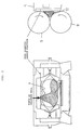
- an extruder including an extruder body 1 and a roller die 2.
- the extruder body 1 includes a pair of right and left extruding screws 3, a chamber 4 in which the screws 3 are rotatably supported, and a motor 5 for rotationally driving the screws 3.
- the chamber 4 includes a hopper 6 for charging a material to the upper surface and an outlet 7 for discharging the material from the front end.
- the pair of screws 3 are cooperatively connected together through a gear reducer 8 at the rear ends, and are exposed at the front ends to the outlet 7 of the chamber 6.
- the roller die 2 includes a pair of upper and lower rollers 9 located before the outlet 7 of the chamber 4.
- the pair of rollers 9 are cooperatively connected together through a gear reducer 10 so as to be rotated in reverse directions, and are rotationally driven by a calender roll drive motor 11.
- a bank portion 12 for accumulating a material to be extruded is defined between the outlet 7 of the chamber 4 and the rollers 9.
- the bank portion 12 is provided with a pair of pressure sensors 13 for detecting a bank pressure (pressure of the material accumulated in the bank portion 12) and bank quantity detecting means 14 for detecting a bank quantity (quantity of the material accumulated in the bank portion 12).
- Each pressure sensor 13 is constructed of a load cell, a resin pressure gage, etc.
- the pair of pressure sensors 13 are located in the bank portion 12 at right and left positions thereof between the two rollers 9.
- the bank quantity detecting means 14 is constructed as a level sensor employing a phototube or the like, and is located at such a position as to sense when the level of the material accumulated in the bank portion 12 reaches a predetermined level.
- the bank quantity detecting means 14 is designed to detect a single level.
- the screw drive motor 5, the calender roll drive motor 11, the pressure sensors 13, and the bank quantity detecting means 14 are connected to a control device 15.
- the control device 15 includes processing means 16 connected to the pressure sensors 13 and the bank quantity detecting means 14, a screw drive motor control panel 17 and a calender drive motor control panel 18 both adapted to be operated by commands from the processing means 16.
- the processing means 16 functions to feed back the difference between a pressure detected by the pressure sensors 13 and a set target pressure to the screw drive motor control panel 17 or the calender drive motor control panel 18, control a screw speed or a roller die speed, and maintain a bank quantity of the material accumulated in the bank portion 12 at a target quantity.
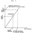
- the processing means 16 obtains the correlation between a bank quantity and a bank pressure from the detected bank quantity and the detected bank pressure.
- the bank quantity detecting means 14 detects a single level as mentioned above. Therefore, as shown in Fig. 4, the relation between the detected bank quantity and the detected bank pressure is obtained as a single point. That is, the correlation is obtained as a straight line, i.e., as a constant of proportion between a bank quantity and a bank pressure. As shown in Fig. 4, the processing means 16 functions to convert a target value of the bank quantity into a pressure value by using the proportional constant obtained above and set this pressure value to the target pressure mentioned above.
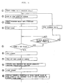
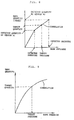
- Fig. 5 shows a flowchart of processing to be performed by the processing means 16, and Fig. 6 shows a change in bank quantity with time elapsed.
- the material fed into the bank portion 12 gradually increases in quantity.
- the detecting means 14 is turned on to detect the level of the material (step 2).
- the calender drive motor 11 for the roller die 2 is automatically started to rotate the rollers 9 at a line speed (constant speed) (step 3).
- the quantity of the material to be discharged from the outlet 7 corresponding to the initially set constant speed of the screws 3 is set greater than the quantity of the material to be extruded from the bank portion 12 corresponding to the line speed of the rollers 9. Therefore, the material fed into the bank portion 12 continues to increase over the predetermined detection level of the bank quantity detecting means 14.
- the level of the material in the bank portion 12 continues to be greater than the detection level of the bank quantity detecting means 14 for a predetermined time period (about 4 to 10 seconds) (steps 4 and 5)
- the screws 3 are once stopped (step 6).
- the bank quantity gradually decreases and the level of the material in the bank portion 12 reaches the predetermined detection level of the bank quantity detecting means 14 as shown in Fig. 3. At this time, the bank quantity detecting means 14 is turned off (step 7).
- step 8 the bank quantity detecting means 14 is turned off, the bank pressure is detected by the pressure sensors 13, and the constant of proportion between the bank quantity and the bank pressure is decided as shown in Fig. 4 (step 8).
- the target value (which is preliminarily set) of the bank quantity in the bank portion 12 is converted into a pressure value by proportional calculation with use of the above-obtained proportional constant as shown in Fig. 4.
- This pressure value is then set as the target pressure, and the difference between the target pressure and an actual measured value of the bank pressure is fed back to control the screw speed (steps 9 and 10).
- the quantity to pressure conversion is carried out after the level of the material in the bank portion 12 exceeds the detection level of the bank quantity detecting means 14 and is then decreased to reach the detection level.
- the quantity to pressure conversion may be carried out when the level of the material exceeds the detection level (i.e., at the time of step 2).
- the upper surface of the material present in the bank portion 12 is greatly uneven and not smooth as shown in Fig. 2. Accordingly, in terms of improvement in control accuracy, it is more preferable to carry out the quantity to pressure conversion after applying a downward force to a projecting portion of the uneven upper surface of the material to smoothen the upper surface and decrease the bank quantity by rotation of the rollers 9 as shown in Fig. 3.
- Figs. 7 and 8 show a modification of the above preferred embodiment, wherein two sensors as the bank quantity detecting means 14 are located at a lower position and an upper position in the bank portion 12.
- the bank pressure is detected by the pressure sensors 13. Accordingly, the correlation between the bank quantity and the bank pressure can be obtained as a broken line as shown in Fig. 8.
- a plurality of levels more than the two levels may be detected by the bank quantity detecting means 14.
- the correlation between the bank quantity and the bank pressure can be obtained as a curve f(x) as shown in Fig. 9.
- the correlation is obtained as an expression of conversion from a bank quantity to a bank pressure by the processing means 16.
- the processing means 16 converts the target value of the bank quantity in the bank portion 12 into a pressure value and sets this pressure value as the target pressure mentioned above. Then, the difference between the target pressure and an actual measured value of the bank pressure is fed back to control the screw speed.
- Fig. 10 shows another preferred embodiment of the present invention, in which the control device 15 further includes storing means 19.
- the correlation between the bank quantity and the bank pressure is obtained at the time of actual operation, whereas in this preferred embodiment the correlation between the bank-quantity and the bank pressure is preliminarily obtained and stored in the storing means 19.
- a preliminary test is performed by using a rubber material having given characteristics to obtain the correlation between the bank quantity and the bank pressure as shown in Fig. 11 and store it in the storing means 19.
- the processing means 16 in the control device 15 shown in Fig. 10 has the following function.
- a bank pressure is detected by the pressure sensors 13 to obtain the relation between the detected bank quantity and the detected bank pressure. Then, as shown in Fig. 12, the correlation stored in the storing means 19 is corrected so that the relation obtained in the actual operation satisfies the stored correlation. Then, with use of the corrected correlation, the target value of the bank quantity is converted into a pressure value, and this pressure value is set as the target pressure.
- the correction of the correlation means to keep the form of a curved line representing the correlation and expand or contract the graph so that the curved line passes the intersection between the detected bank quantity and the detected bank pressure. That is, even when the hardness of the rubber changes, the distribution of the rubber in the bank portion 12 is substantially uniform, so that the same relational expression can be applied.
- the present invention is not limited to the above preferred embodiments.
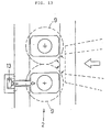
- the pressure sensors 13 for detecting the bank pressure are provided in the bank portion 12 in the above preferred embodiments, they may be constructed as a load cell provided outside the bank portion 12 so as to detect a load applied to the rollers 9 of the roller die 2, thus indirectly detecting the bank pressure as shown in Fig. 13. Further, pressure in the chamber 4 containing the extruding screws 3 may be detected to thereby indirectly detect the bank pressure.
- the kind and the location of the pressure sensor according to the present invention are not limited provided that it can detect the bank pressure.
- the bank quantity detecting means 14 is constructed as a level sensor for detecting a certain level, which sensor consists of a light emitting element and a light receiving element in the above preferred embodiments
- the bank quantity detecting means according to the present invention may be constructed as a sensor capable of continuously detecting the level or a contact type potentiometer as described in Japanese Patent Publication No. 57-26936.
- the bank quantity detecting means 14 in the above preferred embodiments detects the level of the material in the bank portion as the bank quantity
- the bank quantity detecting means according to the present invention may detect the volume, weight, etc. of the material as the bank quantity.
- the bank quantity used in the present invention includes not only the level of the material but also the volume, weight, etc. of the material or a dimensionless index etc.
- control device 15 controls the rotational speed of the screws 3 in the above preferred embodiments
- control device according to the present invention may control the rotational speed of the rollers 9 or control both the speed of the screws 3 and the speed of the rollers 9.
- a bank quantity adjusting device for an extruder capable of accurately controlling a bank quantity regardless of a difference in composition of a material to be extruded.
- the bank quantity adjusting device includes a pressure sensor 13 for detecting a bank pressure between an outlet 7 of an extruder body 1 provided with material extruding screws 3 and a roller die 2 provided before the outlet 7, and a control device 15 for controlling one or both of a screw speed and a roller die speed according to a difference between the bank pressure detected by the pressure sensor 13 and a set target pressure.
- the bank quantity adjusting device further includes bank quantity detecting means 14 for detecting a bank quantity between the outlet 7 and the roller die 2, and processing means 16 provided in the control device 15 for obtaining a correlation between the bank quantity and the bank pressure from a detection value of the bank quantity detected by the bank quantity detecting means 14 and a detection value of the bank pressure detected by the pressure sensor 13 upon detection of the bank quantity, converting a target value of the bank quantity into a pressure value by using the correlation obtained above, and setting this pressure value to the above target pressure.
Landscapes
- Engineering & Computer Science (AREA)
- Mechanical Engineering (AREA)
- Manufacturing & Machinery (AREA)
- Extrusion Moulding Of Plastics Or The Like (AREA)
- Casting Or Compression Moulding Of Plastics Or The Like (AREA)
Applications Claiming Priority (4)
| Application Number | Priority Date | Filing Date | Title |
|---|---|---|---|
| JP229079/93 | 1993-09-14 | ||
| JP22907993 | 1993-09-14 | ||
| JP5306611A JP2698037B2 (ja) | 1993-09-14 | 1993-12-07 | 押出機のバンク量調節装置 |
| JP306611/93 | 1993-12-07 |
Publications (2)
| Publication Number | Publication Date |
|---|---|
| EP0645230A1 true EP0645230A1 (de) | 1995-03-29 |
| EP0645230B1 EP0645230B1 (de) | 1998-07-15 |
Family
ID=26528624
Family Applications (1)
| Application Number | Title | Priority Date | Filing Date |
|---|---|---|---|
| EP94114391A Expired - Lifetime EP0645230B1 (de) | 1993-09-14 | 1994-09-13 | Wulstmengeeinstellungsvorrichtung für Strangpresse |
Country Status (5)
| Country | Link |
|---|---|
| US (1) | US5565219A (de) |
| EP (1) | EP0645230B1 (de) |
| JP (1) | JP2698037B2 (de) |
| KR (1) | KR0149067B1 (de) |
| DE (1) | DE69411649T2 (de) |
Cited By (1)
| Publication number | Priority date | Publication date | Assignee | Title |
|---|---|---|---|---|
| US6330024B1 (en) | 1996-09-05 | 2001-12-11 | The Goodyear Tire & Rubber Company | System and method for controlling the size of material banks in calenders, mills, and feed mills |
Families Citing this family (7)
| Publication number | Priority date | Publication date | Assignee | Title |
|---|---|---|---|---|
| JP2871565B2 (ja) * | 1995-12-26 | 1999-03-17 | 株式会社神戸製鋼所 | ローラヘッド押出機とその制御方法 |
| US6941019B1 (en) | 2000-05-10 | 2005-09-06 | International Business Machines Corporation | Reentry into compressed data |
| US7146053B1 (en) | 2000-05-10 | 2006-12-05 | International Business Machines Corporation | Reordering of compressed data |
| SE0300127D0 (sv) * | 2003-01-17 | 2003-01-17 | Imego Ab | Indicator arrangement |
| FR2922808B1 (fr) * | 2007-10-30 | 2010-02-19 | Michelin Soc Tech | Dispositif pour l'extrusion d'une bande de gomme. |
| JP5027717B2 (ja) * | 2008-04-08 | 2012-09-19 | 株式会社モリヤマ | 2軸押出機 |
| JP6662747B2 (ja) * | 2016-10-07 | 2020-03-11 | 株式会社神戸製鋼所 | スクリュ式押出機 |
Citations (7)
| Publication number | Priority date | Publication date | Assignee | Title |
|---|---|---|---|---|
| JPS6233615A (ja) * | 1985-08-08 | 1987-02-13 | Toshiba Mach Co Ltd | プラスチツクシ−ト成形方法 |
| JPS62236716A (ja) * | 1986-04-07 | 1987-10-16 | Fuji Electric Co Ltd | ストツクバンクセンサ |
| JPH01123720A (ja) * | 1987-11-10 | 1989-05-16 | Bridgestone Corp | ローラヘッド押出機 |
| DE4034144A1 (de) * | 1989-10-27 | 1991-05-02 | Goodyear Tire & Rubber | Strangpresswalz-vorrichtung und verfahren zu deren betrieb |
| EP0429161A1 (de) * | 1989-11-21 | 1991-05-29 | Toshiba Kikai Kabushiki Kaisha | Walzenknetstärke-Überwachungsverfahren und -vorrichtung, Folienherstellungsverfahren und -vorrichtung und Folientemperaturmessverfahren und -vorrichtung |
| JPH05104607A (ja) * | 1991-10-21 | 1993-04-27 | Kobe Steel Ltd | ローラダイ付押出機 |
| EP0560142A1 (de) * | 1992-03-10 | 1993-09-15 | Ishikawajima-Harima Heavy Industries Co., Ltd. | Verfahren und Vorrichtung zur Regelung der Walzspalte eines Kalanders |
Family Cites Families (9)
| Publication number | Priority date | Publication date | Assignee | Title |
|---|---|---|---|---|
| JPS554575A (en) * | 1978-06-27 | 1980-01-14 | Noboru Nakatani | Method and apparatus for measuring flow velocity distribution and flow rate by laser doppler method |
| JPS55166234A (en) * | 1979-06-12 | 1980-12-25 | Kobe Steel Ltd | Noncontact type extruding machine with roller die |
| JPS56118841A (en) * | 1980-02-25 | 1981-09-18 | Kobe Steel Ltd | Regulator for bank amount in extruder for rubber and the like |
| DE3730043A1 (de) * | 1987-09-08 | 1989-03-16 | Reifenhaeuser Masch | Verfahren und extrusionsanlage zum herstellen einer kunststoffbahn |
| US4810179A (en) * | 1988-01-27 | 1989-03-07 | Marshall & Williams Company | Force indicator for casting machines |
| JPH0316223A (ja) * | 1989-06-14 | 1991-01-24 | Matsushita Electron Corp | 半導体装置の製造方法 |
| GB2237239B (en) * | 1989-10-27 | 1993-09-01 | Reifenhaeuser Masch | A process for the production of a ribbon of synthetic thermoplastic material in sheet form |
| JPH0410917A (ja) * | 1990-04-27 | 1992-01-16 | Kobe Steel Ltd | ローラヘッド押出機のバンクボトムプレート移動装置 |
| JPH0410918A (ja) * | 1990-04-27 | 1992-01-16 | Kobe Steel Ltd | ローラヘッド押出機のバンク量検出装置 |
-
1993
- 1993-12-07 JP JP5306611A patent/JP2698037B2/ja not_active Expired - Lifetime
-
1994
- 1994-09-12 KR KR1019940022925A patent/KR0149067B1/ko not_active Expired - Fee Related
- 1994-09-13 US US08/305,349 patent/US5565219A/en not_active Expired - Fee Related
- 1994-09-13 DE DE69411649T patent/DE69411649T2/de not_active Expired - Fee Related
- 1994-09-13 EP EP94114391A patent/EP0645230B1/de not_active Expired - Lifetime
Patent Citations (7)
| Publication number | Priority date | Publication date | Assignee | Title |
|---|---|---|---|---|
| JPS6233615A (ja) * | 1985-08-08 | 1987-02-13 | Toshiba Mach Co Ltd | プラスチツクシ−ト成形方法 |
| JPS62236716A (ja) * | 1986-04-07 | 1987-10-16 | Fuji Electric Co Ltd | ストツクバンクセンサ |
| JPH01123720A (ja) * | 1987-11-10 | 1989-05-16 | Bridgestone Corp | ローラヘッド押出機 |
| DE4034144A1 (de) * | 1989-10-27 | 1991-05-02 | Goodyear Tire & Rubber | Strangpresswalz-vorrichtung und verfahren zu deren betrieb |
| EP0429161A1 (de) * | 1989-11-21 | 1991-05-29 | Toshiba Kikai Kabushiki Kaisha | Walzenknetstärke-Überwachungsverfahren und -vorrichtung, Folienherstellungsverfahren und -vorrichtung und Folientemperaturmessverfahren und -vorrichtung |
| JPH05104607A (ja) * | 1991-10-21 | 1993-04-27 | Kobe Steel Ltd | ローラダイ付押出機 |
| EP0560142A1 (de) * | 1992-03-10 | 1993-09-15 | Ishikawajima-Harima Heavy Industries Co., Ltd. | Verfahren und Vorrichtung zur Regelung der Walzspalte eines Kalanders |
Non-Patent Citations (4)
| Title |
|---|
| PATENT ABSTRACTS OF JAPAN vol. 11, no. 215 (M - 606) 11 July 1987 (1987-07-11) * |
| PATENT ABSTRACTS OF JAPAN vol. 12, no. 105 (M - 681) 6 April 1988 (1988-04-06) * |
| PATENT ABSTRACTS OF JAPAN vol. 13, no. 369 (M - 860) 16 August 1989 (1989-08-16) * |
| PATENT ABSTRACTS OF JAPAN vol. 17, no. 455 (M - 1466) 20 August 1993 (1993-08-20) * |
Cited By (1)
| Publication number | Priority date | Publication date | Assignee | Title |
|---|---|---|---|---|
| US6330024B1 (en) | 1996-09-05 | 2001-12-11 | The Goodyear Tire & Rubber Company | System and method for controlling the size of material banks in calenders, mills, and feed mills |
Also Published As
| Publication number | Publication date |
|---|---|
| DE69411649T2 (de) | 1999-01-21 |
| EP0645230B1 (de) | 1998-07-15 |
| KR0149067B1 (ko) | 1998-10-15 |
| KR950008084A (ko) | 1995-04-17 |
| JPH07132524A (ja) | 1995-05-23 |
| US5565219A (en) | 1996-10-15 |
| JP2698037B2 (ja) | 1998-01-19 |
| DE69411649D1 (de) | 1998-08-20 |
Similar Documents
| Publication | Publication Date | Title |
|---|---|---|
| EP0755885A1 (de) | Apparat zum Wickeln eines Streifens aus dünnem Material | |
| EP0645230B1 (de) | Wulstmengeeinstellungsvorrichtung für Strangpresse | |
| US4852515A (en) | Device for automatically controlling coating amount for use in coating machine | |
| US5855830A (en) | Controlling device and method for extruder | |
| US7018191B2 (en) | Plastics extruder dimension and viscosity control system | |
| WO1991013743A1 (en) | Method of controlling injection of injection molding machine | |
| JPH07265042A (ja) | 圧延シートの成形機及びその成形方法 | |
| EP0798097A1 (de) | Extruder mit Rückführungsregelung | |
| KR880002504B1 (ko) | 판두께의 자동제어장치 | |
| JPH0661806B2 (ja) | トグル式型締装置の自動型締力設定方法 | |
| US5076156A (en) | Grain cleaning machine | |
| EP0610268A1 (de) | Verfahren zur regelung einer mahlwalzenspeisevorrichtung zum mahlen von körnigemmaterial. | |
| JPH02137911A (ja) | インフレーション成形ラインにおける成形物の寸法制御装置 | |
| JP3610393B2 (ja) | 押出成形機の吐出量計測装置 | |
| JP2536321B2 (ja) | 押出成形機の押出制御装置 | |
| JPS63104802A (ja) | パリソン長さ自動調節方法 | |
| JP3717556B2 (ja) | 線条体被覆ラインの速度制御装置 | |
| JP2634097B2 (ja) | 精米機 | |
| JPH1086217A (ja) | インフレーション成形工程におけるフイルム厚さ制御装置 | |
| JP2832387B2 (ja) | インフレーシヨンフイルム製造機のフイルム幅制御装置 | |
| EP0477743A2 (de) | Vorrichtung zum Stangpressen und zum gleichzeitigen Schneiden von Gummi | |
| JPS63126719A (ja) | 押出機の制御方法 | |
| CN1180299A (zh) | 用于获得一定重量的用来生产面包的面团部分的方法及相应装置 | |
| JPS6158286B2 (de) | ||
| JPH06285524A (ja) | 圧延機の自動板厚制御方法 |
Legal Events
| Date | Code | Title | Description |
|---|---|---|---|
| PUAI | Public reference made under article 153(3) epc to a published international application that has entered the european phase |
Free format text: ORIGINAL CODE: 0009012 |
|
| 17P | Request for examination filed |
Effective date: 19940913 |
|
| AK | Designated contracting states |
Kind code of ref document: A1 Designated state(s): DE GB IT |
|
| 17Q | First examination report despatched |
Effective date: 19960322 |
|
| GRAG | Despatch of communication of intention to grant |
Free format text: ORIGINAL CODE: EPIDOS AGRA |
|
| GRAG | Despatch of communication of intention to grant |
Free format text: ORIGINAL CODE: EPIDOS AGRA |
|
| GRAH | Despatch of communication of intention to grant a patent |
Free format text: ORIGINAL CODE: EPIDOS IGRA |
|
| GRAH | Despatch of communication of intention to grant a patent |
Free format text: ORIGINAL CODE: EPIDOS IGRA |
|
| GRAA | (expected) grant |
Free format text: ORIGINAL CODE: 0009210 |
|
| AK | Designated contracting states |
Kind code of ref document: B1 Designated state(s): DE GB IT |
|
| REF | Corresponds to: |
Ref document number: 69411649 Country of ref document: DE Date of ref document: 19980820 |
|
| PLBE | No opposition filed within time limit |
Free format text: ORIGINAL CODE: 0009261 |
|
| STAA | Information on the status of an ep patent application or granted ep patent |
Free format text: STATUS: NO OPPOSITION FILED WITHIN TIME LIMIT |
|
| 26N | No opposition filed | ||
| PGFP | Annual fee paid to national office [announced via postgrant information from national office to epo] |
Ref country code: GB Payment date: 20010912 Year of fee payment: 8 |
|
| PGFP | Annual fee paid to national office [announced via postgrant information from national office to epo] |
Ref country code: DE Payment date: 20011001 Year of fee payment: 8 |
|
| REG | Reference to a national code |
Ref country code: GB Ref legal event code: IF02 |
|
| PG25 | Lapsed in a contracting state [announced via postgrant information from national office to epo] |
Ref country code: GB Free format text: LAPSE BECAUSE OF NON-PAYMENT OF DUE FEES Effective date: 20020913 |
|
| PG25 | Lapsed in a contracting state [announced via postgrant information from national office to epo] |
Ref country code: DE Free format text: LAPSE BECAUSE OF NON-PAYMENT OF DUE FEES Effective date: 20030401 |
|
| GBPC | Gb: european patent ceased through non-payment of renewal fee |
Effective date: 20020913 |
|
| PG25 | Lapsed in a contracting state [announced via postgrant information from national office to epo] |
Ref country code: IT Free format text: LAPSE BECAUSE OF NON-PAYMENT OF DUE FEES Effective date: 20050913 |