EP0645952A1 - Procédé de fabrication d'un circuit multicouche - Google Patents
Procédé de fabrication d'un circuit multicouche Download PDFInfo
- Publication number
- EP0645952A1 EP0645952A1 EP94114083A EP94114083A EP0645952A1 EP 0645952 A1 EP0645952 A1 EP 0645952A1 EP 94114083 A EP94114083 A EP 94114083A EP 94114083 A EP94114083 A EP 94114083A EP 0645952 A1 EP0645952 A1 EP 0645952A1
- Authority
- EP
- European Patent Office
- Prior art keywords
- layer
- conductive
- circuit
- sites
- plating
- Prior art date
- Legal status (The legal status is an assumption and is not a legal conclusion. Google has not performed a legal analysis and makes no representation as to the accuracy of the status listed.)
- Withdrawn
Links
Images


Classifications
-
- H—ELECTRICITY
- H10—SEMICONDUCTOR DEVICES; ELECTRIC SOLID-STATE DEVICES NOT OTHERWISE PROVIDED FOR
- H10W—GENERIC PACKAGES, INTERCONNECTIONS, CONNECTORS OR OTHER CONSTRUCTIONAL DETAILS OF DEVICES COVERED BY CLASS H10
- H10W70/00—Package substrates; Interposers; Redistribution layers [RDL]
- H10W70/01—Manufacture or treatment
- H10W70/05—Manufacture or treatment of insulating or insulated package substrates, or of interposers, or of redistribution layers
-
- H—ELECTRICITY
- H05—ELECTRIC TECHNIQUES NOT OTHERWISE PROVIDED FOR
- H05K—PRINTED CIRCUITS; CASINGS OR CONSTRUCTIONAL DETAILS OF ELECTRIC APPARATUS; MANUFACTURE OF ASSEMBLAGES OF ELECTRICAL COMPONENTS
- H05K3/00—Apparatus or processes for manufacturing printed circuits
- H05K3/10—Apparatus or processes for manufacturing printed circuits in which conductive material is applied to the insulating support in such a manner as to form the desired conductive pattern
- H05K3/20—Apparatus or processes for manufacturing printed circuits in which conductive material is applied to the insulating support in such a manner as to form the desired conductive pattern by affixing prefabricated conductor pattern
- H05K3/205—Apparatus or processes for manufacturing printed circuits in which conductive material is applied to the insulating support in such a manner as to form the desired conductive pattern by affixing prefabricated conductor pattern using a pattern electroplated or electroformed on a metallic carrier
-
- H—ELECTRICITY
- H05—ELECTRIC TECHNIQUES NOT OTHERWISE PROVIDED FOR
- H05K—PRINTED CIRCUITS; CASINGS OR CONSTRUCTIONAL DETAILS OF ELECTRIC APPARATUS; MANUFACTURE OF ASSEMBLAGES OF ELECTRICAL COMPONENTS
- H05K3/00—Apparatus or processes for manufacturing printed circuits
- H05K3/46—Manufacturing multilayer circuits
- H05K3/4611—Manufacturing multilayer circuits by laminating two or more circuit boards
- H05K3/4614—Manufacturing multilayer circuits by laminating two or more circuit boards the electrical connections between the circuit boards being made during lamination
- H05K3/4617—Manufacturing multilayer circuits by laminating two or more circuit boards the electrical connections between the circuit boards being made during lamination characterized by laminating only or mainly similar single-sided circuit boards
-
- H—ELECTRICITY
- H05—ELECTRIC TECHNIQUES NOT OTHERWISE PROVIDED FOR
- H05K—PRINTED CIRCUITS; CASINGS OR CONSTRUCTIONAL DETAILS OF ELECTRIC APPARATUS; MANUFACTURE OF ASSEMBLAGES OF ELECTRICAL COMPONENTS
- H05K3/00—Apparatus or processes for manufacturing printed circuits
- H05K3/46—Manufacturing multilayer circuits
- H05K3/4611—Manufacturing multilayer circuits by laminating two or more circuit boards
- H05K3/4626—Manufacturing multilayer circuits by laminating two or more circuit boards characterised by the insulating layers or materials
- H05K3/4632—Manufacturing multilayer circuits by laminating two or more circuit boards characterised by the insulating layers or materials laminating thermoplastic or uncured resin sheets comprising printed circuits without added adhesive materials between the sheets
-
- H—ELECTRICITY
- H05—ELECTRIC TECHNIQUES NOT OTHERWISE PROVIDED FOR
- H05K—PRINTED CIRCUITS; CASINGS OR CONSTRUCTIONAL DETAILS OF ELECTRIC APPARATUS; MANUFACTURE OF ASSEMBLAGES OF ELECTRICAL COMPONENTS
- H05K3/00—Apparatus or processes for manufacturing printed circuits
- H05K3/46—Manufacturing multilayer circuits
- H05K3/4644—Manufacturing multilayer circuits by building the multilayer layer by layer, i.e. build-up multilayer circuits
- H05K3/4647—Manufacturing multilayer circuits by building the multilayer layer by layer, i.e. build-up multilayer circuits by applying an insulating layer around previously made via studs
-
- H—ELECTRICITY
- H05—ELECTRIC TECHNIQUES NOT OTHERWISE PROVIDED FOR
- H05K—PRINTED CIRCUITS; CASINGS OR CONSTRUCTIONAL DETAILS OF ELECTRIC APPARATUS; MANUFACTURE OF ASSEMBLAGES OF ELECTRICAL COMPONENTS
- H05K3/00—Apparatus or processes for manufacturing printed circuits
- H05K3/46—Manufacturing multilayer circuits
- H05K3/4644—Manufacturing multilayer circuits by building the multilayer layer by layer, i.e. build-up multilayer circuits
- H05K3/4682—Manufacture of core-less build-up multilayer circuits on a temporary carrier or on a metal foil
-
- H—ELECTRICITY
- H10—SEMICONDUCTOR DEVICES; ELECTRIC SOLID-STATE DEVICES NOT OTHERWISE PROVIDED FOR
- H10W—GENERIC PACKAGES, INTERCONNECTIONS, CONNECTORS OR OTHER CONSTRUCTIONAL DETAILS OF DEVICES COVERED BY CLASS H10
- H10W70/00—Package substrates; Interposers; Redistribution layers [RDL]
- H10W70/60—Insulating or insulated package substrates; Interposers; Redistribution layers
- H10W70/611—Insulating or insulated package substrates; Interposers; Redistribution layers for connecting multiple chips together
-
- H—ELECTRICITY
- H10—SEMICONDUCTOR DEVICES; ELECTRIC SOLID-STATE DEVICES NOT OTHERWISE PROVIDED FOR
- H10W—GENERIC PACKAGES, INTERCONNECTIONS, CONNECTORS OR OTHER CONSTRUCTIONAL DETAILS OF DEVICES COVERED BY CLASS H10
- H10W70/00—Package substrates; Interposers; Redistribution layers [RDL]
- H10W70/60—Insulating or insulated package substrates; Interposers; Redistribution layers
- H10W70/67—Insulating or insulated package substrates; Interposers; Redistribution layers characterised by their insulating layers or insulating parts
- H10W70/68—Shapes or dispositions thereof
- H10W70/685—Shapes or dispositions thereof comprising multiple insulating layers
-
- H—ELECTRICITY
- H10—SEMICONDUCTOR DEVICES; ELECTRIC SOLID-STATE DEVICES NOT OTHERWISE PROVIDED FOR
- H10W—GENERIC PACKAGES, INTERCONNECTIONS, CONNECTORS OR OTHER CONSTRUCTIONAL DETAILS OF DEVICES COVERED BY CLASS H10
- H10W70/00—Package substrates; Interposers; Redistribution layers [RDL]
- H10W70/60—Insulating or insulated package substrates; Interposers; Redistribution layers
- H10W70/67—Insulating or insulated package substrates; Interposers; Redistribution layers characterised by their insulating layers or insulating parts
- H10W70/69—Insulating materials thereof
-
- H—ELECTRICITY
- H05—ELECTRIC TECHNIQUES NOT OTHERWISE PROVIDED FOR
- H05K—PRINTED CIRCUITS; CASINGS OR CONSTRUCTIONAL DETAILS OF ELECTRIC APPARATUS; MANUFACTURE OF ASSEMBLAGES OF ELECTRICAL COMPONENTS
- H05K1/00—Printed circuits
- H05K1/02—Details
- H05K1/0201—Thermal arrangements, e.g. for cooling, heating or preventing overheating
- H05K1/0203—Cooling of mounted components
- H05K1/0204—Cooling of mounted components using means for thermal conduction connection in the thickness direction of the substrate
- H05K1/0206—Cooling of mounted components using means for thermal conduction connection in the thickness direction of the substrate by printed thermal vias
-
- H—ELECTRICITY
- H05—ELECTRIC TECHNIQUES NOT OTHERWISE PROVIDED FOR
- H05K—PRINTED CIRCUITS; CASINGS OR CONSTRUCTIONAL DETAILS OF ELECTRIC APPARATUS; MANUFACTURE OF ASSEMBLAGES OF ELECTRICAL COMPONENTS
- H05K1/00—Printed circuits
- H05K1/02—Details
- H05K1/0286—Programmable, customizable or modifiable circuits
- H05K1/0287—Programmable, customizable or modifiable circuits having an universal lay-out, e.g. pad or land grid patterns or mesh patterns
- H05K1/0289—Programmable, customizable or modifiable circuits having an universal lay-out, e.g. pad or land grid patterns or mesh patterns having a matrix lay-out, i.e. having selectively interconnectable sets of X-conductors and Y-conductors in different planes
-
- H—ELECTRICITY
- H05—ELECTRIC TECHNIQUES NOT OTHERWISE PROVIDED FOR
- H05K—PRINTED CIRCUITS; CASINGS OR CONSTRUCTIONAL DETAILS OF ELECTRIC APPARATUS; MANUFACTURE OF ASSEMBLAGES OF ELECTRICAL COMPONENTS
- H05K2201/00—Indexing scheme relating to printed circuits covered by H05K1/00
- H05K2201/01—Dielectrics
- H05K2201/0104—Properties and characteristics in general
- H05K2201/0129—Thermoplastic polymer, e.g. auto-adhesive layer; Shaping of thermoplastic polymer
-
- H—ELECTRICITY
- H05—ELECTRIC TECHNIQUES NOT OTHERWISE PROVIDED FOR
- H05K—PRINTED CIRCUITS; CASINGS OR CONSTRUCTIONAL DETAILS OF ELECTRIC APPARATUS; MANUFACTURE OF ASSEMBLAGES OF ELECTRICAL COMPONENTS
- H05K2201/00—Indexing scheme relating to printed circuits covered by H05K1/00
- H05K2201/01—Dielectrics
- H05K2201/0137—Materials
- H05K2201/015—Fluoropolymer, e.g. polytetrafluoroethylene [PTFE]
-
- H—ELECTRICITY
- H05—ELECTRIC TECHNIQUES NOT OTHERWISE PROVIDED FOR
- H05K—PRINTED CIRCUITS; CASINGS OR CONSTRUCTIONAL DETAILS OF ELECTRIC APPARATUS; MANUFACTURE OF ASSEMBLAGES OF ELECTRICAL COMPONENTS
- H05K2201/00—Indexing scheme relating to printed circuits covered by H05K1/00
- H05K2201/09—Shape and layout
- H05K2201/09209—Shape and layout details of conductors
- H05K2201/095—Conductive through-holes or vias
- H05K2201/09563—Metal filled via
-
- H—ELECTRICITY
- H05—ELECTRIC TECHNIQUES NOT OTHERWISE PROVIDED FOR
- H05K—PRINTED CIRCUITS; CASINGS OR CONSTRUCTIONAL DETAILS OF ELECTRIC APPARATUS; MANUFACTURE OF ASSEMBLAGES OF ELECTRICAL COMPONENTS
- H05K2203/00—Indexing scheme relating to apparatus or processes for manufacturing printed circuits covered by H05K3/00
- H05K2203/07—Treatments involving liquids, e.g. plating, rinsing
- H05K2203/0703—Plating
- H05K2203/0726—Electroforming, i.e. electroplating on a metallic carrier thereby forming a self-supporting structure
-
- H—ELECTRICITY
- H05—ELECTRIC TECHNIQUES NOT OTHERWISE PROVIDED FOR
- H05K—PRINTED CIRCUITS; CASINGS OR CONSTRUCTIONAL DETAILS OF ELECTRIC APPARATUS; MANUFACTURE OF ASSEMBLAGES OF ELECTRICAL COMPONENTS
- H05K2203/00—Indexing scheme relating to apparatus or processes for manufacturing printed circuits covered by H05K3/00
- H05K2203/07—Treatments involving liquids, e.g. plating, rinsing
- H05K2203/0703—Plating
- H05K2203/0733—Method for plating stud vias, i.e. massive vias formed by plating the bottom of a hole without plating on the walls
-
- H—ELECTRICITY
- H05—ELECTRIC TECHNIQUES NOT OTHERWISE PROVIDED FOR
- H05K—PRINTED CIRCUITS; CASINGS OR CONSTRUCTIONAL DETAILS OF ELECTRIC APPARATUS; MANUFACTURE OF ASSEMBLAGES OF ELECTRICAL COMPONENTS
- H05K2203/00—Indexing scheme relating to apparatus or processes for manufacturing printed circuits covered by H05K3/00
- H05K2203/11—Treatments characterised by their effect, e.g. heating, cooling, roughening
- H05K2203/1189—Pressing leads, bumps or a die through an insulating layer
-
- H—ELECTRICITY
- H05—ELECTRIC TECHNIQUES NOT OTHERWISE PROVIDED FOR
- H05K—PRINTED CIRCUITS; CASINGS OR CONSTRUCTIONAL DETAILS OF ELECTRIC APPARATUS; MANUFACTURE OF ASSEMBLAGES OF ELECTRICAL COMPONENTS
- H05K3/00—Apparatus or processes for manufacturing printed circuits
- H05K3/10—Apparatus or processes for manufacturing printed circuits in which conductive material is applied to the insulating support in such a manner as to form the desired conductive pattern
- H05K3/20—Apparatus or processes for manufacturing printed circuits in which conductive material is applied to the insulating support in such a manner as to form the desired conductive pattern by affixing prefabricated conductor pattern
-
- H—ELECTRICITY
- H05—ELECTRIC TECHNIQUES NOT OTHERWISE PROVIDED FOR
- H05K—PRINTED CIRCUITS; CASINGS OR CONSTRUCTIONAL DETAILS OF ELECTRIC APPARATUS; MANUFACTURE OF ASSEMBLAGES OF ELECTRICAL COMPONENTS
- H05K3/00—Apparatus or processes for manufacturing printed circuits
- H05K3/22—Secondary treatment of printed circuits
- H05K3/24—Reinforcing of the conductive pattern
- H05K3/243—Reinforcing of the conductive pattern characterised by selective plating, e.g. for finish plating of pads
-
- H—ELECTRICITY
- H05—ELECTRIC TECHNIQUES NOT OTHERWISE PROVIDED FOR
- H05K—PRINTED CIRCUITS; CASINGS OR CONSTRUCTIONAL DETAILS OF ELECTRIC APPARATUS; MANUFACTURE OF ASSEMBLAGES OF ELECTRICAL COMPONENTS
- H05K3/00—Apparatus or processes for manufacturing printed circuits
- H05K3/22—Secondary treatment of printed circuits
- H05K3/28—Applying non-metallic protective coatings
-
- H—ELECTRICITY
- H05—ELECTRIC TECHNIQUES NOT OTHERWISE PROVIDED FOR
- H05K—PRINTED CIRCUITS; CASINGS OR CONSTRUCTIONAL DETAILS OF ELECTRIC APPARATUS; MANUFACTURE OF ASSEMBLAGES OF ELECTRICAL COMPONENTS
- H05K3/00—Apparatus or processes for manufacturing printed circuits
- H05K3/30—Assembling printed circuits with electric components, e.g. with resistors
- H05K3/32—Assembling printed circuits with electric components, e.g. with resistors electrically connecting electric components or wires to printed circuits
- H05K3/328—Assembling printed circuits with electric components, e.g. with resistors electrically connecting electric components or wires to printed circuits by welding
-
- H—ELECTRICITY
- H05—ELECTRIC TECHNIQUES NOT OTHERWISE PROVIDED FOR
- H05K—PRINTED CIRCUITS; CASINGS OR CONSTRUCTIONAL DETAILS OF ELECTRIC APPARATUS; MANUFACTURE OF ASSEMBLAGES OF ELECTRICAL COMPONENTS
- H05K3/00—Apparatus or processes for manufacturing printed circuits
- H05K3/40—Forming printed elements for providing electric connections to or between printed circuits
- H05K3/42—Plated through-holes or plated via connections
- H05K3/423—Plated through-holes or plated via connections characterised by electroplating method
-
- H—ELECTRICITY
- H05—ELECTRIC TECHNIQUES NOT OTHERWISE PROVIDED FOR
- H05K—PRINTED CIRCUITS; CASINGS OR CONSTRUCTIONAL DETAILS OF ELECTRIC APPARATUS; MANUFACTURE OF ASSEMBLAGES OF ELECTRICAL COMPONENTS
- H05K3/00—Apparatus or processes for manufacturing printed circuits
- H05K3/46—Manufacturing multilayer circuits
- H05K3/4644—Manufacturing multilayer circuits by building the multilayer layer by layer, i.e. build-up multilayer circuits
- H05K3/4652—Adding a circuit layer by laminating a metal foil or a preformed metal foil pattern
- H05K3/4658—Adding a circuit layer by laminating a metal foil or a preformed metal foil pattern characterized by laminating a prefabricated metal foil pattern, e.g. by transfer
-
- H—ELECTRICITY
- H10—SEMICONDUCTOR DEVICES; ELECTRIC SOLID-STATE DEVICES NOT OTHERWISE PROVIDED FOR
- H10P—GENERIC PROCESSES OR APPARATUS FOR THE MANUFACTURE OR TREATMENT OF DEVICES COVERED BY CLASS H10
- H10P72/00—Handling or holding of wafers, substrates or devices during manufacture or treatment thereof
- H10P72/70—Handling or holding of wafers, substrates or devices during manufacture or treatment thereof for supporting or gripping
- H10P72/74—Handling or holding of wafers, substrates or devices during manufacture or treatment thereof for supporting or gripping using temporarily an auxiliary support
- H10P72/7424—Handling or holding of wafers, substrates or devices during manufacture or treatment thereof for supporting or gripping using temporarily an auxiliary support used as a support during the manufacture of self-supporting substrates
-
- Y—GENERAL TAGGING OF NEW TECHNOLOGICAL DEVELOPMENTS; GENERAL TAGGING OF CROSS-SECTIONAL TECHNOLOGIES SPANNING OVER SEVERAL SECTIONS OF THE IPC; TECHNICAL SUBJECTS COVERED BY FORMER USPC CROSS-REFERENCE ART COLLECTIONS [XRACs] AND DIGESTS
- Y10—TECHNICAL SUBJECTS COVERED BY FORMER USPC
- Y10T—TECHNICAL SUBJECTS COVERED BY FORMER US CLASSIFICATION
- Y10T29/00—Metal working
- Y10T29/49—Method of mechanical manufacture
- Y10T29/49002—Electrical device making
- Y10T29/49117—Conductor or circuit manufacturing
- Y10T29/49124—On flat or curved insulated base, e.g., printed circuit, etc.
- Y10T29/49126—Assembling bases
-
- Y—GENERAL TAGGING OF NEW TECHNOLOGICAL DEVELOPMENTS; GENERAL TAGGING OF CROSS-SECTIONAL TECHNOLOGIES SPANNING OVER SEVERAL SECTIONS OF THE IPC; TECHNICAL SUBJECTS COVERED BY FORMER USPC CROSS-REFERENCE ART COLLECTIONS [XRACs] AND DIGESTS
- Y10—TECHNICAL SUBJECTS COVERED BY FORMER USPC
- Y10T—TECHNICAL SUBJECTS COVERED BY FORMER US CLASSIFICATION
- Y10T29/00—Metal working
- Y10T29/49—Method of mechanical manufacture
- Y10T29/49002—Electrical device making
- Y10T29/49117—Conductor or circuit manufacturing
- Y10T29/49124—On flat or curved insulated base, e.g., printed circuit, etc.
- Y10T29/49155—Manufacturing circuit on or in base
- Y10T29/49165—Manufacturing circuit on or in base by forming conductive walled aperture in base
Definitions
- This invention relates generally to methods of manufacturing multilayer circuit boards and multichip modules, referred to collectively herein as circuits. More particularly, this invention relates to new and improved methods of manufacturing multilayer circuits wherein interconnections between multichip module assemblies (circuit assemblies) is accomplished in a single lamination step utilizing a fluoropolymer composite material and diffusible conductive material (e.g. a noble metal).
- a fluoropolymer composite material and diffusible conductive material e.g. a noble metal
- a multichip module can be viewed as a packaging technique in which several I/C chips, which may include complex microprocessor chips, memory chips, etc., are interconnected by a high density substrate.
- substrates for MCMs have been known in general for several years, these known prior art substrates for MCMs typically use thin film polyimide based material systems, and those systems have known deficiencies.
- Polyimide dielectric materials suffer from poor thermo-mechanical reliability and stability and electrical performance limitations.
- the polyimide materials usually are thermosetting, and have high elastic modulus, and there is a significant mismatch, i.e., difference, between the coefficient of thermal expansion (CTE) of the polyimide and the copper-conductors and/or other elements of the circuit structures.
- CTE coefficient of thermal expansion
- a liquid form polyimide precursor is applied and then cured; in other processes, a sheet form polyimide prepreg is used.
- a sheet form polyimide prepreg is used.
- Water is often generated during the polyimide cure, and the polyimide equilibrium water absorption is substantial, often in excess of 1%, and the rate of water uptake can be high.
- water diffusion rates in polyimides are often high, so any water in a polyimide MCM substrate structure can diffuse quickly to the polyimide-conductor interface to corrode or otherwise degrade the interface.
- a layer of metal usually chromium is used as a barrier layer between the polyimide and the copper conductors. While this use of a barrier layer can be successful, it adds significant and expensive processing steps and costs to the manufacture of the MCM substrate structure.
- polyimide based substrates for MCMs are thin film structures.
- the layers of polyimide are typically in the range of 5 to 12 microns in thickness, with conductor line thickness in the range of 2 to 7 microns.
- Those relatively thin conductor lines mean relatively high resistance and relatively high loss; and both the nature of the polyimide material, per se, and the relatively thin layers used, result in poor electrical insulation characteristics.
- Multilayer circuits are also well known and comprise a plurality of stacked substrate/circuit trace assemblies with interconnections between selected locations on the spaced circuit traces.
- Conventional manufacturing techniques for multilayer circuits generally do not yield multiple levels of interconnect, i.e. easy interconnection from one layer to any other layer without significant loss of density and/or major increases in processing costs. This limits the circuit density and the number of substrates.
- step intensive sequential process techniques are usually utilized with much reduced yields.
- U.S. Patent No. 4,788,766 attempts to overcome these problems.
- This prior patent discloses a method wherein a multilayer assembly is made up of a number of individual circuit boards and each board has a substrate on which a first conductive layer is formed on one surface while a second conductive layer is formed on the opposite surface.
- the substrate is a dielectric material which insulates the conductive layers.
- Via holes are formed through the first conductive layer, the substrate and the second conductive layer at various locations.
- An outer conductive material, such as copper, is applied over the first and second conductive layers and onto the side walls of the holes.
- a conductive bonding material is then deposited onto the outer conductive material in the area around the holes.
- the individual boards are stacked in a predetermined order and orientation with a suitable low temperature dielectric bonding ply (meaning that the bonding ply has a lower softening temperature than the circuit substrate material) positioned between each pair of layers.
- the dielectric bonding ply requires registered apertures therethrough which correspond to areas where the conductive layer of one substrate is to make an electrically conductive connection with the conductive layer of an adjacent substrate.
- the dielectric bonding ply integrally bonds adjacent boards together while providing electrical isolation and/or electrical connections between conductive layers of different boards.
- the assembly of the boards is then subjected to a cycle of heat and pressure to effect a bond between the various board layers.
- U.S. Patent No. 5,046,238 attempts to overcome these problems.
- This prior patent discloses a method wherein a plurality of circuit layers comprised of a dielectric substrate having a circuit formed thereon are stacked, one on top of the other.
- the dielectric substrate is composed of a polymeric material capable of undergoing fusion bonding such as a fluoropolymeric based substrate.
- Fusible conductive bonding material e.g., solder
- selected exposed circuit traces prior to the stacking step
- the entire stack is subjected to lamination under heat and pressure to simultaneously fuse all of the substrate and conductive layers together to form an integral multilayer circuit having solid conductive interconnects.
- the discrete circuit layers are each prepared by (1) forming traces and pads on a removable mandrel; (2) laminating a layer of dielectric to the circuit and mandrel; (3) forming an access opening at selected locations through the dielectric layer (using laser, plasma, ion etch or mechanical drilling techniques) to expose selected circuit locations; (4) forming conductive posts in the access openings to a level below the top of the access openings; and (5) providing a fusible conductive material in the access opening. Thereafter, a stack-up is made of a plurality of these discrete circuit layers so that the exposed fusible conductive material contacts selected locations on an adjacent circuit. This stack-up is then subjected to heat and pressure to simultaneously fuse both the several layers of dielectric substrate and fusible conductive material to provide a cohesive fused multilayer circuit board.
- At least one discrete circuit board is made using any suitable technique to define a fusible dielectric substrate having a circuit pattern thereon.
- a layer of fusible dielectric material having openings through selected locations is placed on the circuit board so that selected locations on the circuit pattern are exposed.
- a plug of fusible conductive material e.g., solder
- a second circuit board is stacked on the first board so that the plugs of fusible conductive material align with and contact selected locations on the circuit pattern of the second circuit board. This stack-up is then subjected to heat and pressure to simultaneously fuse both the layers of fusible dielectric and the fusible conductive material to provide a cohesive fused multilayer circuit board.
- thermoplastic materials are generally not useful for fabricating very dense circuits with these harsh bonding conditions.
- Fluoropolymers dielectric materials are often used for high frequency applications (>1 GHz) due to their low loss and tight dielectric constant control.
- Fluoropolymers such as polytetrafluoroethylene (PTFE), a copolymer of tetrafluorethylene and perfluoroalkyl vinyl ether (PFA) and a copolymer of hexafluoropropylene and tetrafluoroethylene (FEP) are also excellent circuit substrates due to their good thermal stability up to 400°C and their good self-adhesion characteristics above their melt point. However, these materials generally have poor creep characteristics and yield poor dimensional stability when circuitized.
- PTFE polytetrafluoroethylene
- PFA perfluoroalkyl vinyl ether
- FEP hexafluoropropylene and tetrafluoroethylene
- Thermal compression bonding processes can be practiced at relatively low, temperatures and moderate pressures as described in U.S. Patent No. 3,923,231.
- the time required for bonding is extremely long (22-30 days) so these processes are generally not practical for printed circuit board or multichip module applications.
- To yield practical bonding times ( ⁇ 5 hour soak times), it is necessary to use relatively high temperatures (>300°C) and pressures (>69 bar (1000 psi)).
- U.S. Patent No. 4,874,721 describes a gold bonding process with pressures of about 2 kg/mm2 (193 bar (2800 psi)) and 400°C in 1 hour.
- a method of forming a multilayer circuit which comprises the steps of: providing at least one first circuit assembly formed by the steps of,
- a circuit assembly is manufactured in an additive process using at least one layer of a fluoropolymer composite material and a conductive material.
- the conductive layers are plated, and the fluoropolymer composite layers are laminated.
- the use of the filled fluoropolymer composite eliminates the need for a barrier layer between the insulation and the conductors.
- a plurality of these circuit assemblies are stacked, one on top of the other.
- a diffusible conductive material e.g., nobel metal
- lead lines or circuit traces
- vias wherever electrical connections are desired.
- the circuits are subjected to lamination under heat and pressure to fuse adjacent fluoropolymer composite material and diffuse adjacent diffusible conductive material together to form an integral multilayer circuit having solid conductive interconnects.
- a barrier metallization i.e., nickel
- Barrier metals are not required if both lead lines and vias are comprised of noble metal, as in the alternative embodiment.
- the fluoropolymer composite dielectric material used in the MCM substrate of the present invention is preferably the material known as RO2800, available from Rogers Corporation, Rogers, Connecticut, the assignee of the present invention. That material is a thermoplastic polytetrafluoroethylene material with silane coated ceramic filler. That fluoropolymer material is set forth in more detail in commonly assigned U.S. Patent Nos. 4,849,284 and 5,061,548.
- the thermoplastic nature of the material combined with a high filler content (preferably greater than 50 vol. % and most preferably greater than 60 vol. %) imparts a high viscosity at the melt temperature. Therefore, the material can be repeatedly remelted without losing dimensional stability during sequential manufacturing steps.
- the dielectric material has a low modulus of elasticity (7 - 8 Kbar (100 - 120 Kpsi)) and a low CTE, thus resulting in low stress both during the manufacturing process and in the use of the resulting structure. Also, the material is characterized by low moisture absorption on the order of less 0.13%.
- Fused amorphous silica contents between 55 vol% and 70 vol% in PTFE have been found to yield good dimensional stability with copper or gold conductors.
- the precise filler content for good dimensional stability does vary somewhat with particle size distribution and filler.
- FIGURES 1 through 13 show part of a circuit in its process of manufacture.
- FIGS 1 through 13 show part of a circuit in its process of manufacture.
- only one, or a few, of each type of via, lead lines, and/or voltage and ground planes is shown for purposes of illustration. It will, however, be understood that the number and type of lead lines, vias and/or voltage and ground planes will be determined by the specific design and function of any particular circuit.
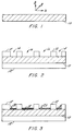
- the process of the present invention starts with a flat platform 10 on which one or more layers of the MCM substrate (or circuit assembly) is to be built, and which may form a part of the finished MCM substrate structure.
- This process may be the same as described in U.S. Patent Application Serial No. 847,859 entitled Multichip Module Substrate and Method of Manufacture Thereof filed March 9, 1992, the entire contents of which are incorporated herein by reference.
- the copper surface of platform 10, on which the MCM substrate is to be built must be as flat as possible.
- Platform 10 can be a copper sheet, preferably of 50,8 micron (2 mil) thick copper foil with parallel flat opposed top and bottom surfaces.
- the platform could also be other material that is dimensionally stable in the x (horizontally in the plane of the drawing paper), y (into the plane of the paper) and z (vertically along the plane of the paper) directions; is flat; has a CTE approximately equal to or slightly less than that of copper, and can be etched or otherwise removed (e.g. laser ablation) at the point in the process where the copper foil is etched off.
- Platform 10 could also be a flat, rigid ceramic element, either featureless or cofired. Such a platform would end up as the outer layer in the final multilayer structure.
- platform 10 comprises a 50,8 micron (2 mil) thick treated copper foil having flat and parallel top and bottom surfaces.
- Both surfaces of the platform 10 are coated with a layer 12 of photoresist material, preferably a dry film photoresist 25,4 micron (1 mil) thick.
- the photoresist layer 12 on the upper treated surface of the platform 10 is imaged and developed to define via sites 14 and lead line sites 16 (in this example, the portion of the lead line site 16 shown is in the "Y" direction), see FIGURE 2.
- the photoresist layer 12 on the untreated bottom surface of the platform 10 is completely exposed (i.e., hardened) to form a protective layer during electroplating of the circuit features.
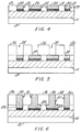
- a thin layer 18 of nickel is plated on platform 10 in the via sites 14 and lead line sites 16.
- a layer 20 of a noble metal (e.g., gold) or other suitable diffusible conductive material is electroplated on the layer 18 of nickel.
- Layer 18 of nickel prevents the diffusion of the copper of platform 10 into the gold of layer 20. This diffusion would otherwise degrade the later bondability of the gold.
- a thin layer of nickel may be deposited on platform 10 prior to coating with photoresist material 12, and then gold only would be plated into the via sites 14 and lead line sites 16. This embodiment may be preferred since it will ensure a more planar surface when the copper platform 10 and nickel layer 18 are etched, as described hereinafter.
- the remaining thickness of the via sites 14 and lead line sites 16 are then electroplated with a layer 22 of copper, after plating another thin nickel (barrier) layer 24 on the gold layer 20.
- the copper plating of layer 22 is controlled so that the height of the plated features is equal to the height of the photoresist layer 12, see FIGURE 4. Care must be taken so that the electroplated features do not 'mushroom' over the top surface of the photoresist layer 12.
- Layers 18, 20, 24 and 22 in via sites 14 form vias 23 and in lead line sites 16 form lead lines 25.
- the via sites 28 are then plated up with a layer 30 of copper to form vias 31.
- the plating of copper layer 30 is controlled so that the tops of vias 31 are at or just below the top surface 33 of the photoresist layer 26. Again, care is taken so that the electroplated features (i.e., layer 30) do not mushroom over the surface of the photoresist, see FIGURE 6.
- plated features 32 comprise nickel layer 18, gold layer 20, nickel layer 24, and copper layers 22 and 30.
- Any residual photoresist is removed preferably using an argon/oxygen plasma etch. It will be appreciated that this plasma etching step is used through the method of the present invention to remove residual photoresist.
- a layer 34 of a fluoropolymeric material (e.g. Rogers Corporation RO2800 fluoropolymer) is deposited on top of the vias and lead lines 32 and laminated thereto.
- Fluoropolymer layer 34 may be from 50,8-254 micron (2-10 mil) thick, preferably 127-254 (5-10 mil) thick. It will be appreciated that the thinner the final dielectric thickness after flycutting, described below, the thinner the dielectric thickness needed in lamination.
- the fluoropolymer material preferably has a thin (e.g., 25,4 micron (1 mil) ) top layer 36 of copper which services as a release layer during lamination.
- the fluoropolymer layer 34 is laminated to platform 10, with plated features 32 by a heat and pressure lamination process.
- release layer 36 prevents the fluoropolymer layer 34 from sticking to a press pad, which in turn, is in contact with the press plate.
- the lamination process densifies the fluoropolymer layer 34 in the z direction.
- the material is a highly filled and viscous polymer which does not flow laterally (x or y directions) under heat and pressure. Thus, the positioning and alignment of the vias and lead lines are not disturbed by lateral flow of the fluoropolymer of layer 34 during the lamination step.
- the upper surface of the assembly is planarized by flycutting to (a) ensure general planarity (i.e., parallelism) with the upper surface of platform 10, and (b) to provide an upper surface 38 of the assembly where the vias 31 are exposed and are generally coplanar with each other and with the exposed upper surface 38 of laminated fluoropolymer layer 34, see FIGURE 9.
- the flycutting is performed as described in U.S. Patent Application Serial No. 847,895.
- the subassembly is then removed from the flycutting machine and cleaned with a Freon or other degreasing material.
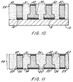
- barrier nickel 40 is plated on the exposed vias followed by the plating of another noble metal (e.g., gold) layer 42, see FIGURE 10.
- another noble metal e.g., gold
- the tops of the vias 31 are plasma cleaned to remove any fluoropolymer debris produced during flycutting, and (b) the bottom surface of the platform 10 is again coated with a layer of photoresist (not shown) to prevent plating on the backside of the platform, which is removed after the gold plating and prior to the etching (i.e., removal) of the platform 10 in the next step.
- the final step to produce the individual circuit layer is to etch off the copper platform 10 and the nickel layer 18 beneath it.
- the resulting circuit 44 shown in FIGURE 11, comprises fluoropolymeric dielectric layer 34 of a uniform thickness, with copper vias and lead lines 23, 25 and 31, the exposed surfaces of which are plated with fusible gold layers 20 and 42 (with nickel barrier layers 24 and 40, respectively) and are essentially flush with the surfaces of the dielectric layer 34. While circuit 44 has been described as a single layer circuit, the circuit may comprise more than one layer, as described in U.S. Patent Application Serial No. 847,895.
- a variation of the preceding circuit fabrication process is one in which, after plating the thin layer 18 of barrier nickel, see FIGURE 3, the vias and lead lines are entirely built of a plated noble metal (e.g., gold), thereby eliminating all copper plating and subsequent nickel platings and the numerous metallic interfaces resulting from the multiple plating steps.
- a plated noble metal e.g., gold
- FIGURE 12 a plurality of circuit layers which have been fabricated in accordance with the techniques shown in Figures 1 - 11 are stacked one on top of the other in the manner shown.
- any number (Xn) of circuits may be stacked and registered with one another such that selected areas of the noble metal layers from adjacent circuits align.
- all surfaces to be diffusion bonded are argon plasma cleaned.
- the stack up is subjected to lamination under sufficient heat (preferably less than 400°C) and pressure, as described in U.S. Patent Application Serial No. 939,105 entitled Method of Manufacturing a Multilayer Circuit Board filed September 1, 1992, so as to fuse adjacent dielectric material and diffuse adjacent noble metal and thereby provide an integral and cohesive multilayer circuit assembly 46, as shown in FIGURE 13 having solid conductive interconnects.
- circuits were manufactured using the process of FIGURES 1 - 11 where: the diffusible conductive material was gold; the vias and traces were 50mm and 25mm wide, respectively; and the fluoropolymer was polytetrafluoroethylene (PTFE) filled with 60 volume percent 1mm fused amorphous silica.
- PTFE polytetrafluoroethylene
- individual circuit layers made in the heretofore described embodiment may be alternated in a stack with double sided, plated-through-hole printed circuits made from the copper clad R02800 dielectric by e.g. conventional, low cost subtractive printed circuit fabrication processes.
- the double sided circuits would, of course, have gold or other diffusible metallurgy on the outer surfaces where diffused conductive interconnects are to be made during the stack lamination.
- the stack lamination could be effected in the same manner as described earlier in U.S. Patent Application Serial No. 939,105.
Landscapes
- Engineering & Computer Science (AREA)
- Manufacturing & Machinery (AREA)
- Microelectronics & Electronic Packaging (AREA)
- Production Of Multi-Layered Print Wiring Board (AREA)
Applications Claiming Priority (2)
| Application Number | Priority Date | Filing Date | Title |
|---|---|---|---|
| US08/127,975 US5440805A (en) | 1992-03-09 | 1993-09-27 | Method of manufacturing a multilayer circuit |
| US127975 | 1993-09-27 |
Publications (1)
| Publication Number | Publication Date |
|---|---|
| EP0645952A1 true EP0645952A1 (fr) | 1995-03-29 |
Family
ID=22432952
Family Applications (1)
| Application Number | Title | Priority Date | Filing Date |
|---|---|---|---|
| EP94114083A Withdrawn EP0645952A1 (fr) | 1993-09-27 | 1994-09-08 | Procédé de fabrication d'un circuit multicouche |
Country Status (3)
| Country | Link |
|---|---|
| US (1) | US5440805A (fr) |
| EP (1) | EP0645952A1 (fr) |
| JP (1) | JPH07170069A (fr) |
Cited By (10)
| Publication number | Priority date | Publication date | Assignee | Title |
|---|---|---|---|---|
| WO2004088731A3 (fr) * | 2003-03-28 | 2004-12-02 | Georgia Tech Res Inst | Procedes de fabrication de structures d'interconnexion organiques tridimensionnelles |
| US6900708B2 (en) | 2002-06-26 | 2005-05-31 | Georgia Tech Research Corporation | Integrated passive devices fabricated utilizing multi-layer, organic laminates |
| US6987307B2 (en) | 2002-06-26 | 2006-01-17 | Georgia Tech Research Corporation | Stand-alone organic-based passive devices |
| EP1439575A3 (fr) * | 2003-01-16 | 2006-10-04 | Matsushita Electric Industrial Co., Ltd. | Dispositif semi-conducteur avec une grille de connexion et son procédé de fabrication |
| US7439840B2 (en) | 2006-06-27 | 2008-10-21 | Jacket Micro Devices, Inc. | Methods and apparatuses for high-performing multi-layer inductors |
| US7489914B2 (en) | 2003-03-28 | 2009-02-10 | Georgia Tech Research Corporation | Multi-band RF transceiver with passive reuse in organic substrates |
| US7808434B2 (en) | 2006-08-09 | 2010-10-05 | Avx Corporation | Systems and methods for integrated antennae structures in multilayer organic-based printed circuit devices |
| US7989895B2 (en) | 2006-11-15 | 2011-08-02 | Avx Corporation | Integration using package stacking with multi-layer organic substrates |
| US8345433B2 (en) | 2004-07-08 | 2013-01-01 | Avx Corporation | Heterogeneous organic laminate stack ups for high frequency applications |
| EP2479788A3 (fr) * | 2006-12-04 | 2015-02-25 | Shinko Electric Industries Co., Ltd. | Substrat de câblage et son procédé de fabrication |
Families Citing this family (75)
| Publication number | Priority date | Publication date | Assignee | Title |
|---|---|---|---|---|
| US5948533A (en) * | 1990-02-09 | 1999-09-07 | Ormet Corporation | Vertically interconnected electronic assemblies and compositions useful therefor |
| US5782891A (en) * | 1994-06-16 | 1998-07-21 | Medtronic, Inc. | Implantable ceramic enclosure for pacing, neurological, and other medical applications in the human body |
| DE69532491T2 (de) * | 1994-07-29 | 2004-12-02 | World Properties, Inc., Lincolnwood | Fluorpolymer-Verbundmaterialien mit zwei oder mehreren keramischen Füllern zur unabhängigen Kontrolle über Dimensionsstabilität und Dielektrizitätskonstante |
| US5487218A (en) * | 1994-11-21 | 1996-01-30 | International Business Machines Corporation | Method for making printed circuit boards with selectivity filled plated through holes |
| WO1998044545A1 (fr) * | 1997-04-03 | 1998-10-08 | W.L. Gore & Associates, Inc. | Procede de perfectionnement de l'adhesion d'un film mince submicronique de type polymere fluore sur un dispositif electronique |
| AU6042698A (en) * | 1997-04-03 | 1998-10-22 | W.L. Gore & Associates, Inc. | Method to improve adhesion of a thin submicron fluoropolymer film on an electronic device |
| JPH1154930A (ja) * | 1997-07-30 | 1999-02-26 | Ngk Spark Plug Co Ltd | 多層配線基板の製造方法 |
| US5980785A (en) * | 1997-10-02 | 1999-11-09 | Ormet Corporation | Metal-containing compositions and uses thereof, including preparation of resistor and thermistor elements |
| US6099677A (en) * | 1998-02-13 | 2000-08-08 | Merrimac Industries, Inc. | Method of making microwave, multifunction modules using fluoropolymer composite substrates |
| DE69903741T2 (de) * | 1998-08-18 | 2003-09-11 | Gore Enterprise Holdings Inc | Verunreinigungswiderstandsfähige - reinigbare - lichtreflektierende oberfläche |
| JP3119630B2 (ja) * | 1998-09-18 | 2000-12-25 | 日本電気株式会社 | 半導体チップモジュール用多層回路基板およびその製造方法 |
| US6332568B1 (en) * | 2000-01-14 | 2001-12-25 | Sandia Corporation | Wafer scale micromachine assembly method |
| JP2001345549A (ja) * | 2000-06-01 | 2001-12-14 | Fujitsu Ltd | 実装用基板の製造方法及び部品実装方法並びに実装用基板製造装置 |
| JP2002305378A (ja) * | 2000-07-06 | 2002-10-18 | Sumitomo Bakelite Co Ltd | 多層配線板およびその製造方法ならびに半導体装置 |
| JP4094286B2 (ja) * | 2000-12-19 | 2008-06-04 | 住友ベークライト株式会社 | アライメント方法 |
| JP2002290048A (ja) * | 2001-03-23 | 2002-10-04 | Fujitsu Ltd | 多層回路基板におけるビア形成方法 |
| US6930256B1 (en) * | 2002-05-01 | 2005-08-16 | Amkor Technology, Inc. | Integrated circuit substrate having laser-embedded conductive patterns and method therefor |
| US6810583B2 (en) | 2001-08-07 | 2004-11-02 | International Business Machines Corporation | Coupling of conductive vias to complex power-signal substructures |
| US9691635B1 (en) | 2002-05-01 | 2017-06-27 | Amkor Technology, Inc. | Buildup dielectric layer having metallization pattern semiconductor package fabrication method |
| US7548430B1 (en) | 2002-05-01 | 2009-06-16 | Amkor Technology, Inc. | Buildup dielectric and metallization process and semiconductor package |
| US7399661B2 (en) * | 2002-05-01 | 2008-07-15 | Amkor Technology, Inc. | Method for making an integrated circuit substrate having embedded back-side access conductors and vias |
| US20080043447A1 (en) * | 2002-05-01 | 2008-02-21 | Amkor Technology, Inc. | Semiconductor package having laser-embedded terminals |
| US7670962B2 (en) | 2002-05-01 | 2010-03-02 | Amkor Technology, Inc. | Substrate having stiffener fabrication method |
| JP4261943B2 (ja) * | 2003-03-05 | 2009-05-13 | Tdk株式会社 | 電子部品の製造方法および、電子部品 |
| TW200507218A (en) * | 2003-03-31 | 2005-02-16 | North Corp | Layout circuit substrate, manufacturing method of layout circuit substrate, and circuit module |
| EP1471575A1 (fr) * | 2003-04-24 | 2004-10-27 | Samsung Electronics Co., Ltd. | Support à puce rf avec un composant inductif intégré et procédé pour sa fabrication |
| JP2004327948A (ja) * | 2003-04-24 | 2004-11-18 | Sanei Kagaku Kk | 多層回路基板及びその製造法 |
| US7414505B2 (en) * | 2003-05-13 | 2008-08-19 | Samsung Electronics Co., Ltd. | High frequency inductor having low inductance and low inductance variation and method of manufacturing the same |
| US7330357B2 (en) * | 2003-09-22 | 2008-02-12 | Intel Corporation | Integrated circuit die/package interconnect |
| US11081370B2 (en) | 2004-03-23 | 2021-08-03 | Amkor Technology Singapore Holding Pte. Ltd. | Methods of manufacturing an encapsulated semiconductor device |
| US10811277B2 (en) | 2004-03-23 | 2020-10-20 | Amkor Technology, Inc. | Encapsulated semiconductor package |
| US7145238B1 (en) | 2004-05-05 | 2006-12-05 | Amkor Technology, Inc. | Semiconductor package and substrate having multi-level vias |
| JP2006108211A (ja) * | 2004-10-01 | 2006-04-20 | North:Kk | 配線板と、その配線板を用いた多層配線基板と、その多層配線基板の製造方法 |
| KR20070068445A (ko) * | 2004-10-06 | 2007-06-29 | 테세라 인터커넥트 머터리얼즈, 인크. | 유전체의 표면에 매입된 금속 트레이스들을 갖는 상호접속소자를 제조하는 구조와 방법 |
| US8826531B1 (en) | 2005-04-05 | 2014-09-09 | Amkor Technology, Inc. | Method for making an integrated circuit substrate having laminated laser-embedded circuit layers |
| IL171378A (en) * | 2005-10-11 | 2010-11-30 | Dror Hurwitz | Integrated circuit support structures and the fabrication thereof |
| US20070111491A1 (en) * | 2005-11-13 | 2007-05-17 | Hsu Jun C | Process for electroplating metal layer without plating lines after the solder mask process |
| US7969823B2 (en) * | 2005-11-21 | 2011-06-28 | Thales Underwater Systems Pty Limited | Methods, systems and apparatus for measuring acoustic pressure |
| US7682972B2 (en) * | 2006-06-01 | 2010-03-23 | Amitec-Advanced Multilayer Interconnect Technoloiges Ltd. | Advanced multilayer coreless support structures and method for their fabrication |
| US7589398B1 (en) | 2006-10-04 | 2009-09-15 | Amkor Technology, Inc. | Embedded metal features structure |
| DE102007034402B4 (de) * | 2006-12-14 | 2014-06-18 | Advanpack Solutions Pte. Ltd. | Halbleiterpackung und Herstellungsverfahren dafür |
| US7608538B2 (en) * | 2007-01-05 | 2009-10-27 | International Business Machines Corporation | Formation of vertical devices by electroplating |
| US7752752B1 (en) | 2007-01-09 | 2010-07-13 | Amkor Technology, Inc. | Method of fabricating an embedded circuit pattern |
| US7874065B2 (en) * | 2007-10-31 | 2011-01-25 | Nguyen Vinh T | Process for making a multilayer circuit board |
| US8320083B1 (en) * | 2007-12-06 | 2012-11-27 | Magnecomp Corporation | Electrical interconnect with improved corrosion resistance for a disk drive head suspension |
| KR100956632B1 (ko) * | 2007-12-17 | 2010-05-11 | 주식회사 심텍 | 초박형 반도체 패키지 기판, 반도체 패키지 기판의제조방법, 및 이를 이용한 반도체 소자의 제조방법 |
| KR20100126714A (ko) * | 2008-01-30 | 2010-12-02 | 이노벤트 테크놀로지스, 엘엘씨 | 비아 디스크 제조를 위한 방법 및 장치 |
| JP5154963B2 (ja) * | 2008-02-04 | 2013-02-27 | 新光電気工業株式会社 | 配線基板の製造方法 |
| JP2011527830A (ja) * | 2008-07-09 | 2011-11-04 | テセラ・インターコネクト・マテリアルズ,インコーポレイテッド | 導体間隙が縮小された超小型電子相互接続素子 |
| US20110008600A1 (en) * | 2008-12-29 | 2011-01-13 | Walsh Edward D | Chemical barrier lamination and method |
| US8872329B1 (en) | 2009-01-09 | 2014-10-28 | Amkor Technology, Inc. | Extended landing pad substrate package structure and method |
| US8809690B2 (en) * | 2010-03-04 | 2014-08-19 | Rogers Corporation | Dielectric bond plies for circuits and multilayer circuits, and methods of manufacture thereof |
| JP5273749B2 (ja) * | 2011-03-09 | 2013-08-28 | インターナショナル・ビジネス・マシーンズ・コーポレーション | プリント配線板の製造方法 |
| US9888568B2 (en) | 2012-02-08 | 2018-02-06 | Crane Electronics, Inc. | Multilayer electronics assembly and method for embedding electrical circuit components within a three dimensional module |
| JP5680589B2 (ja) * | 2012-06-25 | 2015-03-04 | 新光電気工業株式会社 | 配線基板 |
| US9230726B1 (en) | 2015-02-20 | 2016-01-05 | Crane Electronics, Inc. | Transformer-based power converters with 3D printed microchannel heat sink |
| JP6932475B2 (ja) * | 2015-03-26 | 2021-09-08 | 住友ベークライト株式会社 | 有機樹脂基板の製造方法、有機樹脂基板および半導体装置 |
| US10455708B2 (en) * | 2015-06-29 | 2019-10-22 | Samsung Electro-Mechanics Co., Ltd. | Multilayered substrate and method for manufacturing the same |
| US10388608B2 (en) * | 2015-08-28 | 2019-08-20 | Hitachi Chemical Company, Ltd. | Semiconductor device and method for manufacturing same |
| KR102212356B1 (ko) | 2016-01-28 | 2021-02-03 | 로저스코포레이션 | 플루오로폴리머 복합 필름 래핑된 와이어들 및 케이블들 |
| JP7187821B2 (ja) * | 2018-05-29 | 2022-12-13 | Tdk株式会社 | プリント配線板およびその製造方法 |
| JP7119583B2 (ja) * | 2018-05-29 | 2022-08-17 | Tdk株式会社 | プリント配線板およびその製造方法 |
| US20220068563A1 (en) * | 2019-01-07 | 2022-03-03 | Queen Mary University Of London | Process for producing a poly(vinyliden fluoride) dielectric material for capacitor with rich beta cristalline phase |
| JP7238548B2 (ja) * | 2019-03-29 | 2023-03-14 | Tdk株式会社 | 多層基板用絶縁シート、多層基板および多層基板の製造方法 |
| JP7455516B2 (ja) * | 2019-03-29 | 2024-03-26 | Tdk株式会社 | 素子内蔵基板およびその製造方法 |
| JP2019204974A (ja) * | 2019-08-21 | 2019-11-28 | 住友ベークライト株式会社 | 有機樹脂基板の製造方法、有機樹脂基板および半導体装置 |
| TWI833095B (zh) | 2020-07-28 | 2024-02-21 | 美商聖高拜塑膠製品公司 | 敷銅層板、含其之印刷電路基板及其形成方法 |
| TWI864310B (zh) | 2020-07-28 | 2024-12-01 | 愛爾蘭商范斯福複合材料有限公司 | 介電基板及含彼之包銅層板及印刷電路板 |
| KR102919122B1 (ko) | 2020-12-16 | 2026-01-29 | 생-고뱅 퍼포먼스 플라스틱스 코포레이션 | 구리-클래드 라미네이트 및 이의 형성 방법 |
| CN116530220A (zh) | 2020-12-16 | 2023-08-01 | 美国圣戈班性能塑料公司 | 介电基板及其形成方法 |
| JP7649855B2 (ja) | 2020-12-16 | 2025-03-21 | バーシブ コンポジッツ リミテッド | 誘電体基板及びその形成方法 |
| CN112638041B (zh) * | 2020-12-25 | 2022-03-08 | 深圳光韵达激光应用技术有限公司 | 一种散热基板制作工艺 |
| US20230057113A1 (en) * | 2021-08-19 | 2023-02-23 | Taiwan Semiconductor Manufacturing Company, Ltd. | Semiconductor device, package structure and method of fabricating the same |
| US11973034B2 (en) * | 2021-08-25 | 2024-04-30 | Applied Materials, Inc. | Nanotwin copper materials in semiconductor devices |
| CN115588748B (zh) * | 2022-12-07 | 2023-04-11 | 四川启睿克科技有限公司 | 一种电池与电路板的集成装置及其制备方法 |
Citations (4)
| Publication number | Priority date | Publication date | Assignee | Title |
|---|---|---|---|---|
| GB2049297A (en) * | 1979-05-18 | 1980-12-17 | Pactel Corp | Method of manufacturing printed circuitry |
| US4685210A (en) * | 1985-03-13 | 1987-08-11 | The Boeing Company | Multi-layer circuit board bonding method utilizing noble metal coated surfaces |
| US5046238A (en) * | 1990-03-15 | 1991-09-10 | Rogers Corporation | Method of manufacturing a multilayer circuit board |
| EP0560077A2 (fr) * | 1992-03-09 | 1993-09-15 | Rogers Corporation | Substrat pour module multi-puce et procédé de sa fabrication |
Family Cites Families (42)
| Publication number | Priority date | Publication date | Assignee | Title |
|---|---|---|---|---|
| GB1353671A (en) * | 1971-06-10 | 1974-05-22 | Int Computers Ltd | Methods of forming circuit interconnections |
| US3953924A (en) * | 1975-06-30 | 1976-05-04 | Rockwell International Corporation | Process for making a multilayer interconnect system |
| SE404863B (sv) * | 1975-12-17 | 1978-10-30 | Perstorp Ab | Forfarande vid framstellning av ett flerlagerkort |
| US4306925A (en) * | 1977-01-11 | 1981-12-22 | Pactel Corporation | Method of manufacturing high density printed circuit |
| US4159222A (en) * | 1977-01-11 | 1979-06-26 | Pactel Corporation | Method of manufacturing high density fine line printed circuitry |
| US4446477A (en) * | 1981-08-21 | 1984-05-01 | Sperry Corporation | Multichip thin film module |
| JPS60214941A (ja) * | 1984-04-10 | 1985-10-28 | 株式会社 潤工社 | プリント基板 |
| US4667220A (en) * | 1984-04-27 | 1987-05-19 | Trilogy Computer Development Partners, Ltd. | Semiconductor chip module interconnection system |
| US4647508A (en) * | 1984-07-09 | 1987-03-03 | Rogers Corporation | Flexible circuit laminate |
| US4915983A (en) * | 1985-06-10 | 1990-04-10 | The Foxboro Company | Multilayer circuit board fabrication process |
| US4692839A (en) * | 1985-06-24 | 1987-09-08 | Digital Equipment Corporation | Multiple chip interconnection system and package |
| US4605471A (en) * | 1985-06-27 | 1986-08-12 | Ncr Corporation | Method of manufacturing printed circuit boards |
| US4634631A (en) * | 1985-07-15 | 1987-01-06 | Rogers Corporation | Flexible circuit laminate and method of making the same |
| US4702792A (en) * | 1985-10-28 | 1987-10-27 | International Business Machines Corporation | Method of forming fine conductive lines, patterns and connectors |
| US4874721A (en) * | 1985-11-11 | 1989-10-17 | Nec Corporation | Method of manufacturing a multichip package with increased adhesive strength |
| US4902606A (en) * | 1985-12-20 | 1990-02-20 | Hughes Aircraft Company | Compressive pedestal for microminiature connections |
| JPS6366993A (ja) * | 1986-09-08 | 1988-03-25 | 日本電気株式会社 | 多層配線基板 |
| JPH07112041B2 (ja) * | 1986-12-03 | 1995-11-29 | シャープ株式会社 | 半導体装置の製造方法 |
| US5061548A (en) * | 1987-02-17 | 1991-10-29 | Rogers Corporation | Ceramic filled fluoropolymeric composite material |
| US4849284A (en) * | 1987-02-17 | 1989-07-18 | Rogers Corporation | Electrical substrate material |
| US4755911A (en) * | 1987-04-28 | 1988-07-05 | Junkosha Co., Ltd. | Multilayer printed circuit board |
| JPS63274199A (ja) * | 1987-05-06 | 1988-11-11 | Hitachi Ltd | 多層配線の形成方法 |
| US4788766A (en) * | 1987-05-20 | 1988-12-06 | Loral Corporation | Method of fabricating a multilayer circuit board assembly |
| AU610249B2 (en) * | 1987-09-29 | 1991-05-16 | Microelectronics And Computer Technology Corporation | Customizable circuitry |
| US4922377A (en) * | 1987-11-16 | 1990-05-01 | Hitachi, Ltd. | Module and a substrate for the module |
| FR2625042B1 (fr) * | 1987-12-22 | 1990-04-20 | Thomson Csf | Structure microelectronique hybride modulaire a haute densite d'integration |
| US4926241A (en) * | 1988-02-19 | 1990-05-15 | Microelectronics And Computer Technology Corporation | Flip substrate for chip mount |
| US4868350A (en) * | 1988-03-07 | 1989-09-19 | International Business Machines Corporation | High performance circuit boards |
| LU87259A1 (fr) * | 1988-06-27 | 1990-02-28 | Ceca Comm Europ Charbon Acier | Procede et dispositif de traitement de signaux electriques provenant de l'analyse d'une ligne d'une image |
| US4810332A (en) * | 1988-07-21 | 1989-03-07 | Microelectronics And Computer Technology Corporation | Method of making an electrical multilayer copper interconnect |
| US4995941A (en) * | 1989-05-15 | 1991-02-26 | Rogers Corporation | Method of manufacture interconnect device |
| US5049974A (en) * | 1989-05-15 | 1991-09-17 | Roger Corporation | Interconnect device and method of manufacture thereof |
| US5097393A (en) * | 1989-05-15 | 1992-03-17 | Rogers Corporation | Multilayer interconnect device and method of manufacture thereof |
| US5055425A (en) * | 1989-06-01 | 1991-10-08 | Hewlett-Packard Company | Stacked solid via formation in integrated circuit systems |
| US5010641A (en) * | 1989-06-30 | 1991-04-30 | Unisys Corp. | Method of making multilayer printed circuit board |
| US5011580A (en) * | 1989-10-24 | 1991-04-30 | Microelectronics And Computer Technology Corporation | Method of reworking an electrical multilayer interconnect |
| US5040929A (en) * | 1989-11-30 | 1991-08-20 | Fuller Company | Loading system for particulate materials |
| US5030499A (en) * | 1989-12-08 | 1991-07-09 | Rockwell International Corporation | Hermetic organic/inorganic interconnection substrate for hybrid circuit manufacture |
| US5129142A (en) * | 1990-10-30 | 1992-07-14 | International Business Machines Corporation | Encapsulated circuitized power core alignment and lamination |
| US5329695A (en) * | 1992-09-01 | 1994-07-19 | Rogers Corporation | Method of manufacturing a multilayer circuit board |
| US5274912A (en) * | 1992-09-01 | 1994-01-04 | Rogers Corporation | Method of manufacturing a multilayer circuit board |
| US5309629A (en) * | 1992-09-01 | 1994-05-10 | Rogers Corporation | Method of manufacturing a multilayer circuit board |
-
1993
- 1993-09-27 US US08/127,975 patent/US5440805A/en not_active Expired - Fee Related
-
1994
- 1994-09-08 EP EP94114083A patent/EP0645952A1/fr not_active Withdrawn
- 1994-09-27 JP JP6231783A patent/JPH07170069A/ja active Pending
Patent Citations (5)
| Publication number | Priority date | Publication date | Assignee | Title |
|---|---|---|---|---|
| GB2049297A (en) * | 1979-05-18 | 1980-12-17 | Pactel Corp | Method of manufacturing printed circuitry |
| US4685210A (en) * | 1985-03-13 | 1987-08-11 | The Boeing Company | Multi-layer circuit board bonding method utilizing noble metal coated surfaces |
| US5046238A (en) * | 1990-03-15 | 1991-09-10 | Rogers Corporation | Method of manufacturing a multilayer circuit board |
| EP0446656A1 (fr) * | 1990-03-15 | 1991-09-18 | Rogers Corporation | Procédé pour la fabrication de platines multi-couches |
| EP0560077A2 (fr) * | 1992-03-09 | 1993-09-15 | Rogers Corporation | Substrat pour module multi-puce et procédé de sa fabrication |
Non-Patent Citations (2)
| Title |
|---|
| G.S. SWEI ET AL.: "Ultra thin fluoropolymer dielectrics for MCM-L", INTERNATIONAL JOURNAL OF MICROCIRCUITS AND ELECTRONIC PACKAGING, vol. 16, no. 2, RESTON VA US, pages 109 - 116, XP000349287 * |
| K.F. GREENE: "Producing printed circuit boards", IBM TECHNICAL DISCLOSURE BULLETIN., vol. 11, no. 12, May 1969 (1969-05-01), NEW YORK US, pages 1676 - 1677 * |
Cited By (14)
| Publication number | Priority date | Publication date | Assignee | Title |
|---|---|---|---|---|
| US6900708B2 (en) | 2002-06-26 | 2005-05-31 | Georgia Tech Research Corporation | Integrated passive devices fabricated utilizing multi-layer, organic laminates |
| US6987307B2 (en) | 2002-06-26 | 2006-01-17 | Georgia Tech Research Corporation | Stand-alone organic-based passive devices |
| US7260890B2 (en) | 2002-06-26 | 2007-08-28 | Georgia Tech Research Corporation | Methods for fabricating three-dimensional all organic interconnect structures |
| US7659634B2 (en) | 2003-01-16 | 2010-02-09 | Panasonic Corporation | Lead frame, method of manufacturing the same, semiconductor device using lead frame and method of manufacturing semiconductor device |
| EP1439575A3 (fr) * | 2003-01-16 | 2006-10-04 | Matsushita Electric Industrial Co., Ltd. | Dispositif semi-conducteur avec une grille de connexion et son procédé de fabrication |
| US7723161B2 (en) | 2003-01-16 | 2010-05-25 | Panasonic Corporation | Lead frame, method of manufacturing the same, semiconductor device using lead frame and method of manufacturing semiconductor device |
| US7489914B2 (en) | 2003-03-28 | 2009-02-10 | Georgia Tech Research Corporation | Multi-band RF transceiver with passive reuse in organic substrates |
| WO2004088731A3 (fr) * | 2003-03-28 | 2004-12-02 | Georgia Tech Res Inst | Procedes de fabrication de structures d'interconnexion organiques tridimensionnelles |
| US7805834B2 (en) | 2003-03-28 | 2010-10-05 | Georgia Tech Research Corporation | Method for fabricating three-dimensional all organic interconnect structures |
| US8345433B2 (en) | 2004-07-08 | 2013-01-01 | Avx Corporation | Heterogeneous organic laminate stack ups for high frequency applications |
| US7439840B2 (en) | 2006-06-27 | 2008-10-21 | Jacket Micro Devices, Inc. | Methods and apparatuses for high-performing multi-layer inductors |
| US7808434B2 (en) | 2006-08-09 | 2010-10-05 | Avx Corporation | Systems and methods for integrated antennae structures in multilayer organic-based printed circuit devices |
| US7989895B2 (en) | 2006-11-15 | 2011-08-02 | Avx Corporation | Integration using package stacking with multi-layer organic substrates |
| EP2479788A3 (fr) * | 2006-12-04 | 2015-02-25 | Shinko Electric Industries Co., Ltd. | Substrat de câblage et son procédé de fabrication |
Also Published As
| Publication number | Publication date |
|---|---|
| US5440805A (en) | 1995-08-15 |
| JPH07170069A (ja) | 1995-07-04 |
Similar Documents
| Publication | Publication Date | Title |
|---|---|---|
| US5440805A (en) | Method of manufacturing a multilayer circuit | |
| US5046238A (en) | Method of manufacturing a multilayer circuit board | |
| US7253512B2 (en) | Organic dielectric electronic interconnect structures and method for making | |
| US5329695A (en) | Method of manufacturing a multilayer circuit board | |
| US5309629A (en) | Method of manufacturing a multilayer circuit board | |
| EP1250033B1 (fr) | Panneau à circuit imprimé et composants électroniques | |
| US7002080B2 (en) | Multilayer wiring board | |
| KR940009175B1 (ko) | 다층 프린트기판의 제조방법 | |
| US6395374B1 (en) | Method of making microwave, multifunction modules using fluoropolymer composite substrates | |
| US6972070B2 (en) | Method of manufacturing a printed wiring board | |
| US5401913A (en) | Electrical interconnections between adjacent circuit board layers of a multi-layer circuit board | |
| EP0435584B1 (fr) | Structure de circuit à plusieurs niveaux | |
| JP3375555B2 (ja) | 回路部品内蔵モジュールおよびその製造方法 | |
| KR101076061B1 (ko) | 3차원의 모든 유기체 배선 구조들을 제조하기 위한 방법 | |
| EP0469308B1 (fr) | Plaquette de circuits à multicouches et son procédé de fabrication | |
| US8222539B2 (en) | Wiring board and method for manufacturing the same | |
| EP0914757B1 (fr) | Procede et circuit d'interconnexion le long de l'axe z | |
| US6639155B1 (en) | High performance packaging platform and method of making same | |
| JP2587596B2 (ja) | 回路基板接続材とそれを用いた多層回路基板の製造方法 | |
| US5274912A (en) | Method of manufacturing a multilayer circuit board | |
| EP0632683A2 (fr) | Panneau rigide-flexible avec structure d'interconnexion anisotrope et procédé de fabrication | |
| EP1109430A2 (fr) | Panneau à circuit double-face et panneau à circuit multicouche le comprenant et procédé de fabrication d'un panneau à circuit double-face | |
| US20100224397A1 (en) | Wiring board and method for manufacturing the same | |
| CN1212115A (zh) | 印刷电路多层组件及其制作方法 | |
| US5709805A (en) | Method for producing multi-layer circuit board and resulting article of manufacture |
Legal Events
| Date | Code | Title | Description |
|---|---|---|---|
| PUAI | Public reference made under article 153(3) epc to a published international application that has entered the european phase |
Free format text: ORIGINAL CODE: 0009012 |
|
| AK | Designated contracting states |
Kind code of ref document: A1 Designated state(s): DE FR GB IT |
|
| 17P | Request for examination filed |
Effective date: 19950803 |
|
| RIN1 | Information on inventor provided before grant (corrected) |
Inventor name: SWEI, GWO S. Inventor name: ARTHUR, DAVID J. Inventor name: OLENICK, JOHN A. Inventor name: SMITH, DAVID W. Inventor name: DAIGLE, ROBERT C. |
|
| 17Q | First examination report despatched |
Effective date: 19951227 |
|
| STAA | Information on the status of an ep patent application or granted ep patent |
Free format text: STATUS: THE APPLICATION IS DEEMED TO BE WITHDRAWN |
|
| 18D | Application deemed to be withdrawn |
Effective date: 19960507 |