EP0646465A2 - Encre pour cartouche à jet d'encre et méthode d'enregistrement à jet d'encre l'utilisant - Google Patents
Encre pour cartouche à jet d'encre et méthode d'enregistrement à jet d'encre l'utilisant Download PDFInfo
- Publication number
- EP0646465A2 EP0646465A2 EP94115375A EP94115375A EP0646465A2 EP 0646465 A2 EP0646465 A2 EP 0646465A2 EP 94115375 A EP94115375 A EP 94115375A EP 94115375 A EP94115375 A EP 94115375A EP 0646465 A2 EP0646465 A2 EP 0646465A2
- Authority
- EP
- European Patent Office
- Prior art keywords
- ink
- ink jet
- chamber
- negative pressure
- producing material
- Prior art date
- Legal status (The legal status is an assumption and is not a legal conclusion. Google has not performed a legal analysis and makes no representation as to the accuracy of the status listed.)
- Granted
Links
- 238000000034 method Methods 0.000 title claims description 36
- 239000000463 material Substances 0.000 claims abstract description 107
- 239000004094 surface-active agent Substances 0.000 claims abstract description 97
- XLYOFNOQVPJJNP-UHFFFAOYSA-N water Chemical compound O XLYOFNOQVPJJNP-UHFFFAOYSA-N 0.000 claims abstract description 66
- 238000004891 communication Methods 0.000 claims abstract description 59
- 239000000693 micelle Substances 0.000 claims abstract description 28
- 239000008213 purified water Substances 0.000 claims abstract description 22
- 239000000976 ink Substances 0.000 claims description 811
- 239000003570 air Substances 0.000 claims description 95
- 238000007639 printing Methods 0.000 claims description 70
- 238000005192 partition Methods 0.000 claims description 61
- 239000007788 liquid Substances 0.000 claims description 27
- 238000010276 construction Methods 0.000 claims description 24
- 239000011148 porous material Substances 0.000 claims description 23
- 238000003780 insertion Methods 0.000 claims description 10
- 230000037431 insertion Effects 0.000 claims description 10
- 239000012080 ambient air Substances 0.000 claims description 8
- 230000001737 promoting effect Effects 0.000 claims 4
- 239000006096 absorbing agent Substances 0.000 description 32
- 230000000694 effects Effects 0.000 description 26
- 230000000740 bleeding effect Effects 0.000 description 24
- 239000002904 solvent Substances 0.000 description 22
- 230000008859 change Effects 0.000 description 20
- 238000002347 injection Methods 0.000 description 18
- 239000007924 injection Substances 0.000 description 18
- -1 poly propylene Polymers 0.000 description 16
- 230000008020 evaporation Effects 0.000 description 15
- 238000001704 evaporation Methods 0.000 description 15
- 230000007613 environmental effect Effects 0.000 description 14
- 230000005499 meniscus Effects 0.000 description 13
- 239000003795 chemical substances by application Substances 0.000 description 12
- 239000003086 colorant Substances 0.000 description 12
- 239000000047 product Substances 0.000 description 12
- 238000011084 recovery Methods 0.000 description 10
- LYCAIKOWRPUZTN-UHFFFAOYSA-N Ethylene glycol Chemical compound OCCO LYCAIKOWRPUZTN-UHFFFAOYSA-N 0.000 description 9
- KFZMGEQAYNKOFK-UHFFFAOYSA-N Isopropanol Chemical compound CC(C)O KFZMGEQAYNKOFK-UHFFFAOYSA-N 0.000 description 9
- 230000007423 decrease Effects 0.000 description 9
- 239000000975 dye Substances 0.000 description 9
- 239000000203 mixture Substances 0.000 description 9
- 230000003204 osmotic effect Effects 0.000 description 9
- 230000006870 function Effects 0.000 description 8
- 238000004519 manufacturing process Methods 0.000 description 8
- 230000008569 process Effects 0.000 description 8
- IAYPIBMASNFSPL-UHFFFAOYSA-N Ethylene oxide Chemical compound C1CO1 IAYPIBMASNFSPL-UHFFFAOYSA-N 0.000 description 7
- 239000012298 atmosphere Substances 0.000 description 7
- 238000009835 boiling Methods 0.000 description 7
- 239000000835 fiber Substances 0.000 description 7
- PEDCQBHIVMGVHV-UHFFFAOYSA-N Glycerine Chemical compound OCC(O)CO PEDCQBHIVMGVHV-UHFFFAOYSA-N 0.000 description 6
- 235000014113 dietary fatty acids Nutrition 0.000 description 6
- 229930195729 fatty acid Natural products 0.000 description 6
- 239000000194 fatty acid Substances 0.000 description 6
- 239000000243 solution Substances 0.000 description 6
- 238000003860 storage Methods 0.000 description 6
- 238000010521 absorption reaction Methods 0.000 description 5
- 230000004888 barrier function Effects 0.000 description 5
- 238000009826 distribution Methods 0.000 description 5
- 239000006260 foam Substances 0.000 description 5
- 150000001298 alcohols Chemical class 0.000 description 4
- 230000008901 benefit Effects 0.000 description 4
- 230000003247 decreasing effect Effects 0.000 description 4
- 230000007547 defect Effects 0.000 description 4
- 238000005516 engineering process Methods 0.000 description 4
- 238000011156 evaluation Methods 0.000 description 4
- 150000004665 fatty acids Chemical class 0.000 description 4
- 239000006261 foam material Substances 0.000 description 4
- 230000033001 locomotion Effects 0.000 description 4
- 230000000717 retained effect Effects 0.000 description 4
- LFQSCWFLJHTTHZ-UHFFFAOYSA-N Ethanol Chemical compound CCO LFQSCWFLJHTTHZ-UHFFFAOYSA-N 0.000 description 3
- ZMXDDKWLCZADIW-UHFFFAOYSA-N N,N-Dimethylformamide Chemical compound CN(C)C=O ZMXDDKWLCZADIW-UHFFFAOYSA-N 0.000 description 3
- 230000009471 action Effects 0.000 description 3
- 238000006243 chemical reaction Methods 0.000 description 3
- 239000002131 composite material Substances 0.000 description 3
- 230000002950 deficient Effects 0.000 description 3
- 235000011187 glycerol Nutrition 0.000 description 3
- 238000010438 heat treatment Methods 0.000 description 3
- WGCNASOHLSPBMP-UHFFFAOYSA-N hydroxyacetaldehyde Natural products OCC=O WGCNASOHLSPBMP-UHFFFAOYSA-N 0.000 description 3
- 239000012071 phase Substances 0.000 description 3
- 238000004321 preservation Methods 0.000 description 3
- 238000003825 pressing Methods 0.000 description 3
- 229920003002 synthetic resin Polymers 0.000 description 3
- 239000000057 synthetic resin Substances 0.000 description 3
- YODZTKMDCQEPHD-UHFFFAOYSA-N thiodiglycol Chemical compound OCCSCCO YODZTKMDCQEPHD-UHFFFAOYSA-N 0.000 description 3
- 229950006389 thiodiglycol Drugs 0.000 description 3
- CSCPPACGZOOCGX-UHFFFAOYSA-N Acetone Chemical compound CC(C)=O CSCPPACGZOOCGX-UHFFFAOYSA-N 0.000 description 2
- IAZDPXIOMUYVGZ-UHFFFAOYSA-N Dimethylsulphoxide Chemical compound CS(C)=O IAZDPXIOMUYVGZ-UHFFFAOYSA-N 0.000 description 2
- 229920005830 Polyurethane Foam Polymers 0.000 description 2
- XSQUKJJJFZCRTK-UHFFFAOYSA-N Urea Chemical compound NC(N)=O XSQUKJJJFZCRTK-UHFFFAOYSA-N 0.000 description 2
- 230000001476 alcoholic effect Effects 0.000 description 2
- HSFWRNGVRCDJHI-UHFFFAOYSA-N alpha-acetylene Natural products C#C HSFWRNGVRCDJHI-UHFFFAOYSA-N 0.000 description 2
- 239000004202 carbamide Substances 0.000 description 2
- ZBNARPCCDMHDDV-UHFFFAOYSA-N chembl1206040 Chemical compound C1=C(S(O)(=O)=O)C=C2C=C(S(O)(=O)=O)C(N=NC3=CC=C(C=C3C)C=3C=C(C(=CC=3)N=NC=3C(=CC4=CC(=CC(N)=C4C=3O)S(O)(=O)=O)S(O)(=O)=O)C)=C(O)C2=C1N ZBNARPCCDMHDDV-UHFFFAOYSA-N 0.000 description 2
- 230000001143 conditioned effect Effects 0.000 description 2
- 238000013461 design Methods 0.000 description 2
- 238000001514 detection method Methods 0.000 description 2
- 150000002148 esters Chemical class 0.000 description 2
- 125000005677 ethinylene group Chemical group [*:2]C#C[*:1] 0.000 description 2
- 125000001153 fluoro group Chemical group F* 0.000 description 2
- KWIUHFFTVRNATP-UHFFFAOYSA-N glycine betaine Chemical compound C[N+](C)(C)CC([O-])=O KWIUHFFTVRNATP-UHFFFAOYSA-N 0.000 description 2
- 230000006872 improvement Effects 0.000 description 2
- 238000007641 inkjet printing Methods 0.000 description 2
- 230000001788 irregular Effects 0.000 description 2
- 239000010410 layer Substances 0.000 description 2
- 239000007791 liquid phase Substances 0.000 description 2
- 238000005259 measurement Methods 0.000 description 2
- 230000007246 mechanism Effects 0.000 description 2
- 239000005022 packaging material Substances 0.000 description 2
- 230000035515 penetration Effects 0.000 description 2
- 230000035699 permeability Effects 0.000 description 2
- 230000005501 phase interface Effects 0.000 description 2
- 239000002985 plastic film Substances 0.000 description 2
- 229920006255 plastic film Polymers 0.000 description 2
- 239000011496 polyurethane foam Substances 0.000 description 2
- 230000002265 prevention Effects 0.000 description 2
- 238000001454 recorded image Methods 0.000 description 2
- 230000004044 response Effects 0.000 description 2
- 150000003839 salts Chemical class 0.000 description 2
- 238000001179 sorption measurement Methods 0.000 description 2
- 239000003381 stabilizer Substances 0.000 description 2
- 230000000087 stabilizing effect Effects 0.000 description 2
- 239000013589 supplement Substances 0.000 description 2
- 238000012360 testing method Methods 0.000 description 2
- RYHBNJHYFVUHQT-UHFFFAOYSA-N 1,4-Dioxane Chemical compound C1COCCO1 RYHBNJHYFVUHQT-UHFFFAOYSA-N 0.000 description 1
- SBASXUCJHJRPEV-UHFFFAOYSA-N 2-(2-methoxyethoxy)ethanol Chemical compound COCCOCCO SBASXUCJHJRPEV-UHFFFAOYSA-N 0.000 description 1
- XNWFRZJHXBZDAG-UHFFFAOYSA-N 2-METHOXYETHANOL Chemical compound COCCO XNWFRZJHXBZDAG-UHFFFAOYSA-N 0.000 description 1
- VAYOSLLFUXYJDT-RDTXWAMCSA-N Lysergic acid diethylamide Chemical compound C1=CC(C=2[C@H](N(C)C[C@@H](C=2)C(=O)N(CC)CC)C2)=C3C2=CNC3=C1 VAYOSLLFUXYJDT-RDTXWAMCSA-N 0.000 description 1
- 239000002202 Polyethylene glycol Substances 0.000 description 1
- 239000004743 Polypropylene Substances 0.000 description 1
- 238000003854 Surface Print Methods 0.000 description 1
- GSEJCLTVZPLZKY-UHFFFAOYSA-N Triethanolamine Chemical compound OCCN(CCO)CCO GSEJCLTVZPLZKY-UHFFFAOYSA-N 0.000 description 1
- 239000011358 absorbing material Substances 0.000 description 1
- 230000001133 acceleration Effects 0.000 description 1
- 239000012790 adhesive layer Substances 0.000 description 1
- 150000004996 alkyl benzenes Chemical class 0.000 description 1
- 150000005215 alkyl ethers Chemical class 0.000 description 1
- 229910052782 aluminium Inorganic materials 0.000 description 1
- XAGFODPZIPBFFR-UHFFFAOYSA-N aluminium Chemical compound [Al] XAGFODPZIPBFFR-UHFFFAOYSA-N 0.000 description 1
- 150000001408 amides Chemical class 0.000 description 1
- 150000001412 amines Chemical class 0.000 description 1
- 150000001413 amino acids Chemical class 0.000 description 1
- 150000003863 ammonium salts Chemical class 0.000 description 1
- 150000001450 anions Chemical class 0.000 description 1
- 238000013459 approach Methods 0.000 description 1
- 229960003237 betaine Drugs 0.000 description 1
- 230000005540 biological transmission Effects 0.000 description 1
- 230000005587 bubbling Effects 0.000 description 1
- 230000015556 catabolic process Effects 0.000 description 1
- 150000001875 compounds Chemical class 0.000 description 1
- 230000006835 compression Effects 0.000 description 1
- 238000007906 compression Methods 0.000 description 1
- 238000009833 condensation Methods 0.000 description 1
- 230000005494 condensation Effects 0.000 description 1
- HPXRVTGHNJAIIH-UHFFFAOYSA-N cyclohexanol Chemical compound OC1CCCCC1 HPXRVTGHNJAIIH-UHFFFAOYSA-N 0.000 description 1
- 238000000354 decomposition reaction Methods 0.000 description 1
- 238000006731 degradation reaction Methods 0.000 description 1
- 230000001419 dependent effect Effects 0.000 description 1
- MTHSVFCYNBDYFN-UHFFFAOYSA-N diethylene glycol Chemical compound OCCOCCO MTHSVFCYNBDYFN-UHFFFAOYSA-N 0.000 description 1
- 230000003292 diminished effect Effects 0.000 description 1
- 238000007599 discharging Methods 0.000 description 1
- 238000006073 displacement reaction Methods 0.000 description 1
- 230000035620 dolor Effects 0.000 description 1
- 239000000428 dust Substances 0.000 description 1
- 150000002170 ethers Chemical class 0.000 description 1
- 229940093476 ethylene glycol Drugs 0.000 description 1
- 238000002474 experimental method Methods 0.000 description 1
- 239000004744 fabric Substances 0.000 description 1
- 239000011888 foil Substances 0.000 description 1
- 230000004927 fusion Effects 0.000 description 1
- 230000005484 gravity Effects 0.000 description 1
- TZMQHOJDDMFGQX-UHFFFAOYSA-N hexane-1,1,1-triol Chemical compound CCCCCC(O)(O)O TZMQHOJDDMFGQX-UHFFFAOYSA-N 0.000 description 1
- 239000004615 ingredient Substances 0.000 description 1
- 230000009545 invasion Effects 0.000 description 1
- 238000011835 investigation Methods 0.000 description 1
- 230000014759 maintenance of location Effects 0.000 description 1
- 239000007769 metal material Substances 0.000 description 1
- 239000002736 nonionic surfactant Substances 0.000 description 1
- 239000003960 organic solvent Substances 0.000 description 1
- 239000000049 pigment Substances 0.000 description 1
- 239000004033 plastic Substances 0.000 description 1
- 229920003023 plastic Polymers 0.000 description 1
- 229920001515 polyalkylene glycol Polymers 0.000 description 1
- 229920001223 polyethylene glycol Polymers 0.000 description 1
- 229920001155 polypropylene Polymers 0.000 description 1
- 229920001451 polypropylene glycol Polymers 0.000 description 1
- 230000002787 reinforcement Effects 0.000 description 1
- 230000002441 reversible effect Effects 0.000 description 1
- 238000005096 rolling process Methods 0.000 description 1
- 229920006395 saturated elastomer Polymers 0.000 description 1
- 238000012216 screening Methods 0.000 description 1
- 238000007789 sealing Methods 0.000 description 1
- 230000035939 shock Effects 0.000 description 1
- 239000002356 single layer Substances 0.000 description 1
- 239000007787 solid Substances 0.000 description 1
- 238000007711 solidification Methods 0.000 description 1
- 230000008023 solidification Effects 0.000 description 1
- 125000006850 spacer group Chemical group 0.000 description 1
- 230000006641 stabilisation Effects 0.000 description 1
- 238000011105 stabilization Methods 0.000 description 1
- 239000000126 substance Substances 0.000 description 1
- 230000000153 supplemental effect Effects 0.000 description 1
- 230000001052 transient effect Effects 0.000 description 1
- 230000007704 transition Effects 0.000 description 1
- JLGLQAWTXXGVEM-UHFFFAOYSA-N triethylene glycol monomethyl ether Chemical compound COCCOCCOCCO JLGLQAWTXXGVEM-UHFFFAOYSA-N 0.000 description 1
- 229960004418 trolamine Drugs 0.000 description 1
- 238000011179 visual inspection Methods 0.000 description 1
- 238000005406 washing Methods 0.000 description 1
Images



















Classifications
-
- B—PERFORMING OPERATIONS; TRANSPORTING
- B41—PRINTING; LINING MACHINES; TYPEWRITERS; STAMPS
- B41J—TYPEWRITERS; SELECTIVE PRINTING MECHANISMS, i.e. MECHANISMS PRINTING OTHERWISE THAN FROM A FORME; CORRECTION OF TYPOGRAPHICAL ERRORS
- B41J2/00—Typewriters or selective printing mechanisms characterised by the printing or marking process for which they are designed
- B41J2/005—Typewriters or selective printing mechanisms characterised by the printing or marking process for which they are designed characterised by bringing liquid or particles selectively into contact with a printing material
- B41J2/01—Ink jet
- B41J2/17—Ink jet characterised by ink handling
- B41J2/175—Ink supply systems ; Circuit parts therefor
- B41J2/17503—Ink cartridges
- B41J2/1752—Mounting within the printer
- B41J2/17523—Ink connection
-
- B—PERFORMING OPERATIONS; TRANSPORTING
- B41—PRINTING; LINING MACHINES; TYPEWRITERS; STAMPS
- B41J—TYPEWRITERS; SELECTIVE PRINTING MECHANISMS, i.e. MECHANISMS PRINTING OTHERWISE THAN FROM A FORME; CORRECTION OF TYPOGRAPHICAL ERRORS
- B41J2/00—Typewriters or selective printing mechanisms characterised by the printing or marking process for which they are designed
- B41J2/005—Typewriters or selective printing mechanisms characterised by the printing or marking process for which they are designed characterised by bringing liquid or particles selectively into contact with a printing material
- B41J2/01—Ink jet
- B41J2/17—Ink jet characterised by ink handling
- B41J2/175—Ink supply systems ; Circuit parts therefor
- B41J2/17503—Ink cartridges
- B41J2/17513—Inner structure
Definitions
- the present invention relates to an ink jet cartridge in use for ink providing jet function, an ink jet cartridge, to an ink jet and also a method therefor, which are applicable for devices including copying machines, recording apparatus such as facsimile devices, telecommunication instruments, composite instruments thereof, and printers.
- An ink jet cartridge in use for an ink jet device is normally integrally formed with an ink jet head
- such a conventional cartridge is replaced together with the used head, when the cartridge is reached the step at which the ink will not be injected.
- a comparatively large amount of ink is still remaining in the cartridge, because of being governed by ink retention ability of sponge material which is contained in the cartridge.
- a foam material is enclosed in the cartridge, which is integral with an ink jet recording head furnished with a plurality of ink injecting orifices.
- foam material such as polyurethane foam
- a negative pressure produced by capillarity of the foam achieves conservation of the ink (i.e. prevention of ink leakage out of the container).
- the filling quantity of ink is not only restricted, but also the amount of ink remaining unused in the foam will increase.
- problems still remain in difficulty of detection of remaining ink and possibility of ununiformity of injecting property of ink.
- Japanese laid-open patent publication No. 2-522 discloses an ink jet head having an integral construction in which a few amount of porous material is provided between an upper positioned primary storage section in which a large amount of ink is contained and a lower positioned ink jet head. According to the description, an advantage is mentioned that, because the porous material is not enclosed in the ink storage section but disposed only in an ink passage, the using efficiency of ink is increased.
- Another advantage is also mentioned that it is possible to tentatively store the ink flown out of the primary ink storage section due to temperature rise of the enclosed air (and pressure decrease thereby) by providing a secondary ink storage section in the side of the porous material, and thus to maintain the negative pressure applied on the head at the recording step at substantially a constant value.
- the production of negative pressure is almost reduced, because the porous material is present in the ink passage, and an over sufficient amount of ink is soaked in the porous material with the ink supplied from the primary ink storage section which is upwardly positioned and stores a large amount of ink. Accordingly, there has been possibility of flowing out of ink from the orifice of the head, even applied with a slight shock. Also, it is not adequate in practice to form the above mentioned type of the ink container as a replaceable type of ink jet cartridge detachable with the ink jet head. The reason therefor is that there is possibility of flowing out of the ink from the head-ink jet cartridge joint portion into the ink container, since the negative pressure is generally diminished.
- Another ink jet cartridge is also known, in which the ink is enclosed in a bag and a spring member is additionally provided to control the deformation of the bag for maintaining the negative pressure of the porous material itself in a predetermined value. But the cost thereof was increased and also it was impossible to maintain the structure of the spring to achieve a mass production of devices.
- any ink jet cartridge for ink jet purpose (that is, non-contact type printing use) manufactured in low cost but provided with a reasonable technical level is not still produced.
- an ink jet recording method using a piezoelectric element recording is performed by injecting ink by use of a drive voltage not less than 40 V in the on-demand mode or continuous mode.
- the element is in usual driven by a driving voltage required to correctly inject the ink in spite of any environmental change.
- An embodiment thereof is disclosed in Japanese patent publication No. 58-6752. It is also disclosed therein a various colored ink containing an amount of 0.0001 to 10 weight % of an ethylene oxide addition product. It is evaluated therein that an ink containing a surface active agent, that is surfactant, is excellent in fixing property and water resistance in comparison with that without surfactant. It is further disclosed therein that it is possible to determine if the ink can be injected by checking the first drive signal obtained after being kept for three months, and that the ink containing a surfactant can perform an excellent ink injection.
- Japanese laid-open patent publication No. 56-49771 discloses an ink material containing a surfactant of not exceeding the critical micelle concentration, and also is mentioned therein such an ink can produce an effect of preventing blinding which occurs in the nozzle.
- Japanese laid-open patent publication No. 1-182384 (1989) discloses an invention on an ink to enable the use of an ink containing 1 to 10 % of a surfactant by admixing a solvent of low vapor pressure and low viscosity. But it is merely considered therein bleeding of the ink with the paper to be printed thereon.
- the invention disclosed therein is a structure which comprises a central section including a recording core, a first cotton-like fiber engaging with the recording core, a second cotton-like fiber absorbing a small amount of ink at the opening in communication with the atmosphere but allowing less passage of ink compared with the first cotton-like fiber; and a tightly sealed ink chamber section capable of feeding through the passages provided on the opposite sides of the central section.
- the air contained in the ink chamber section is expanded due to temperature rise of the ambient temperature to allow the ink to flow into the first cotton-like fiber. Then, the ink of the amount exceeding that possible to be soaked is absorbed by the second fiber to prevent the ink from being overflown and dropped out of the recording core.
- a groove is formed in the range from the lowermost end to the uppermost end of the side surface different from the partition of the central section and the tightly sealed section.
- the same inventors proposed an improved ink jet cartridge for the ink jet device, which is featured in provided with two advantages, that is, an excellent feeding of ink material of an amount corresponding to the amount of ink ejected from the recording head during printing operation, and there is no drawback of ink leakage from the outlet during non-printing, and these were disclosed in Japanese patent application Nos. 4-198474 and 4-198681 of the same inventors.
- the construction which is effective for making best use of ink jet characteristics is comprised of, as the fundamental construction, a first ink chamber and a second ink chamber: the first chamber for receiving a negative pressure producing material, provided with an air communication passage for achieving air communication with the atmosphere, and serving as the container for the negative pressure producing material; and the second chamber being an ink chamber, which is in communication with the first chamber but is substantially in tightly sealed condition, for directly and tentatively accommodating the ink material which is to be supplied into the first chamber.
- the present invention can provide a replaceable ink jet cartridge and a ink jet head as well as a printer, which are in response to the high speed recording.
- an object of the present invention is to provide an innovated ink jet cartridge comprising two chambers.
- Another object of the present invention is to provide ink, which is used for the ink jet cartridge, capable of providing a smooth and stabilized air-liquid interface between the air and the ink in the negative pressure producing material, and of improving the recording ability on the recording medium.
- Another object of the present invention is to provide a method of ink jet recording and a device therefor that is capable of producing a record having an excellent image quality and that have high reliability.
- a further object of the present invention is to provide a method of ink jet recording, which is improved in the smooth and stabilized air-liquid interface between the air and the ink in the negative pressure producing material, and improves the recording ability on the recording medium.
- the present invention is related to the technology, through which a hydrophilic ink containing a surfactant is supplied into the ink jet recording head, and perform recording by the ink on a recording medium, and to the technology related thereto.
- the content of the surfactant is such as the surfactant is contained in the resulting overall ink liquid at a predetermined amount of not exceeding the critical micelle concentration (Abbreviated as "c.m.c.") against that of the ink; but, when the same surfactant is admixed into purified water at the same predetermined content, the concentration will exceed the above c.m.c. concentration.
- the area adjacent the passage which is in communication with ambient air of the negative pressure producing material is formed as the area containing an ink,thereby providing an advantage to prevent leakage of the ink from the passage to the air, regardless of any change of environmental conditions.
- a seal member which is used to seal the air passage area, can be prevented from removal therefrom.
- a necessary amount of air can be supplied into the cartridge, and another effect is produced to suspend the change of negative pressure in the ink jet cartridge.
- the air communication area is formed as having no wet with ink, because the osmotic speed of the ink is further retarded. Still, it may be also formed as the area which is in advance having wet with ink, which is removed thereafter.
- the invention provides a construction comprising an ink supply opening or an area in which the negative pressure producing material is partially compressed or is enabled to be compressed.
- a substantially stabilized ink supply passage can be maintained.
- a "supply tube" of the present invention includes not only an insert tube especially for ink jet, but also includes a valve assembly or connecting member for deforming the negative pressure producing material by applying pressure. All such arrangements provide the effects of stabilized ink feed direction for complete consumption of the ink in the second container. Also after such consumption, the air is allowed to flow from the partition toward the supply tube, accordingly in the direction to eliminate the air from its negative condition. Consequently, the ink in the negative pressure section is enabled to be efficiently consumed, thereby reducing the remaining ink.
- an area which is not compressed by the supply tube and another area which is compressed by the supply tube are provided in this sequence.
- one-directional ink supply passage is formed in the uncompressible area to provide the same effect as mentioned above.
- the amount of the remaining ink is further reduced according to ink retaining ability of the compressible area.
- the invention includes the above-discussed three features. Further, it is to be understood that at least one or two features also can provide excellent effects.
- the ink jet cartridge of the invention is normally manually treated by the operator normally with any trouble. But, sometimes the ink chamber is likely to be deformed when applied with a great pressure.
- another partition is preferably provided, which allows to provide a gap wider than the partition which provides the narrow passage.
- the cartridge is formed by synthetic resin
- the ratio of thickness Ti and Ts is preferably between 1.2 and 3.0.
- an automatic or manual removal of the ink from the cartridge is performed by way of aspiration or ejection: this will allow the ink condition in the negative pressure section to be corrected before printing operation, and therefore, regardless of how the cartridge being kept unused, the original functions of the cartridge mentioned above can be effectively utilized.
- the height of the narrow passage to the lower edge of the partition is larger than the average pore size of the negative pressure producing material, more preferably that of adjacent the area of the narrow passage, that is actually more than 0.1mm, and not exceeding 5mm. For achieving further stability, it may be not exceeding 3mm.
- the ratio of volume of the negative pressure section and the ink chamber the ratio between 1:1 and 1:3 is selected as the optimal value in practice.
- An optimal embodiment according to the invention is the recording method performed under the condition described below and the apparatus therefor.
- the recording ink contains a surfactant such that: the content of the above agent does not exceed the critical micelle concentration (abbreviated in "c.m.c.") compared with the hydrophilic ink containing the same agent ; in addition, the content of the agent is in that: when the agent; in addition, the content of the agent is in that: when the agent is admixed in purified water, the concentration is greater than the c.m.c. in purified water. Further, the content is in the range of not exceeding the half value of (c.m.c. in the ink + c.m.c. in purified water).
- c.m.c. critical micelle concentration
- the hydrophilic ink is supplied to the ink jet head, wherein the agent contains the surfactant in the amount for satisfying the surface tension exceeding 30 dyn/cm under the temperature condition T degrees centigrade.
- the principal effect of the invention includes: the stabilized characteristics in the ink jet cartridge, being supplied to the head under stable supplying condition, stabilization of the condition of ejected ink drops, improved printing quality by single dot form which is free from any bleeding, and also includes the improved recovery of ink ejection, and improved ejection characteristic at high frequency.
- the invention also provides the following effects.
- the surfactant provides the effect of minimizing the variation of viscosity, deriving the further effect of surfactant, and substantially eliminating variation of injecting condition of ink.
- concentration of the surfactant is determined in accordance with the illustrated relationship between the surface tension and the concentration of the surfactant, an appropriate condition for effectively compensating the environmental variations will be obtained.
- the surfactant does not exceed the c.m.c. in ink, and is a predetermined amount close to that of c.m.c. in the ink, while such predetermined amount of the agent is greater than the c.m.c. in purified water, when the amount of the agent is supplied to purified water.
- the hydrophilic ink containing such amount of the surfactant is supplied to the ink jet recording head. Onto the recording medium, the printing is performed using the hydrophilic ink which contains the surfactant in the amount of exceeding the c.m.c. in ink.
- the concentration of the surfactant in view of increasing osmotic action, a concentration as high as possible is preferable; in view of preventing bleeding phenomenon or preservation of printing uniformity, it is preferable that the content will be greater than the c.m.c. in purified water; and in view of improving injection property and printing quality of the single dot, and reducing the load of recovered operation, it is important that a surfactant relative to ink is less than the c.m.c. in the ink.
- FIG. 1 to FIG.6 illustrate an embodiment according to the present invention, in which a narrow passage 8 and an opening 2 is formed which supplies ink onto the surface of a negative pressure producing material, which opposed to a partition 5 formed by a bottom surface of the ink jet cartridge.
- FIG.1 illustrates a fragmentary schematic view of an ink container partially cut out
- FIG.2 is a sectional view of FIG.2.
- an ink jet cartridge body or ink tank 1 has an opening 2 positioned on one side, which is in communication with an ink jet recording head.
- the ink jet cartridge further comprises a negative pressure producing chamber 4, as the first container, enclosing a negative pressure producing material 3 and an ink container 6 as the second container for enclosing the ink only.
- the container 6 faces the negative pressure producing chamber 4 but is separate by a partition 5 therebetween, and in communication therewith along the bottom surface 11.
- the ambient air is therefore supplied through the opening 2, which serves as a passage way for the air.
- the ink is supplied only through the passage 8, so that it is surely supplied toward the opening 2 along the bottom surface 11.
- the air is replaced with the ink enclosed in the container 6 in accordance with the feeding of the ink.
- FIG.3 it is illustrated a replaceable ink jet cartridge according to the invention, into which a joint member 7 is inserted, which serves as the supplier tube for supplying the ink into the ink jet cartridge, and thus the ink jet recording apparatus has turned in the operative condition. Also, on the end of joint member 7, a filter may be attached for discharging dust contained in the ink jet cartridge.
- the ink jet recorder When the ink jet recorder starts operation, the ink is ejected through the orifice provided in the recording head to produce an absorbing force in the ink jet cartridge.
- the ink 9 is introduced from the ink chamber 6, through a narrow passage 8 formed between the edge of partition 5 and bottom surface 11 of the ink jet cartridge, into the negative pressure producing chamber 4, and then, through the negative pressure producing material 3 into joint member 7, and finally supplied to the recording head.
- the pressure within the ink chamber 6 reduces and accordingly, a pressure difference is produced between the ink chamber 6 and negative pressure producing chamber 4. The pressure difference is continued to increase as recording operation continues.
- FIG.4 a construction as shown in FIG.4 is possible, when a suitable material which produces the reduced pressure is selected according to the ink jet head to be associated, and when the chamber 4 and the chamber 6 are designed so that these have an appropriate relationship between their dimension.
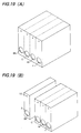
- each of these multi-color inks such as of four colors including black, yellow, magenta, and cyan
- each of separate cartridges may be combined as one body as shown in FIG.19(A), or one for black ink of frequent use is separate from another casing including the remaining colors as shown in FIG.19(A), or one for black ink of frequent use is separate from another including the remaining colors as shown in FIG.19(B).
- the combination thereof may be selected as necessary according to the employed recording device.
- the following items including: selection, form, and dimension of the negative pressure producing material 3; shape and dimension of the partition 5; the shape and dimension of the narrow passage 8 between the partition and the bottom surface 11; the relative volume ratio of chamber 4 and ink chamber 6; the extent of insertion of joint member 7 into the ink jet cartridge, also the shape and dimension of this joint member 7; the shape, dimension and mesh of the filter; and the surface tension of the ink.
- any material which is able to maintain the ink without being affected from its own weight or a slight vibration may be used, such as a cotton-like material formed of a fiber webbed in a meshed form or a porous material.
- Those capable of conserving ink and adjusting the reduced pressure are preferable, such as polyurethane foam or sponge.
- a foam material is preferably used, as can be prepared to have a desirable porosity at the manufactured time.
- a foam, which is further prepared so as to be improved in porous density through thermal pressing, should be subjected to additional treatment such as washing to prevent any inadequate effect by possible decomposition substances.
- porous foam in order to manufacture a replaceable ink jet cartridge which meets with requirements from various ink jet cartridges, the different forms of porous foam are required. In these cases, it is preferable to cut a foam material, which is not subjected to thermal pressing and has a specific number of cells, and is pressed into and secured in the chamber 4 provided for the negative pressure producing material, thereafter its porosity and capillary force are adjusted.
- a gap may be formed between joint member 7 and opening 2 to introduce the air from the exterior, but not limited in such an arrangement.
- Any other structure or configuration may be selected for the joint member 7 and the opening 2.
- an end of joint member 7 may be tapered with respect to the inserting direction of the joint member as shown in FIGS.(a) and (b), for preventing play of joint member from the bottom of the ink jet cartridge and for maintaining and securing the abutting surface between the filter of the end of joint member 7 and negative pressure producing material 3. Since an increased amount of insertion of the member 7 is likely to cause the tapered portion to produce a crack of the member 2, a surface configuration may be selected as shown in FIG.3(c).
- FIG.5 includes various forms therefor: FIG.(a), (b) and (c) show each shape of groove, rectangular, and triangular, respectively.
- the opening 2 is preferably shaped to be formed with a gap in the extent so as not to tightly close the opening. Or, at the lower side of opening 2, that is, at the bottom side of the ink jet cartridge, the opening 2 is shaped to approach the outer surface of the joint member 7, and is open at the upper side of the opening 2.
- the ink jet cartridge of the invention can be of more simple construction, as the opening 2 may also serve as an air inlet.
- the extent of insertion into the ink jet cartridge may be designed in taking account of each shape of the joint member, pressure reducing material, and the ink jet cartridge itself. Also, the area of the pressure reducing material which is to be pressurized and deformed may be defined, so as not to cause ink outflow and ink interruption during recording operation.
- Another air passage be formed in the negative pressure producing material chamber 4.
- Such a construction is effective to provide an area of the negative pressure producing material which contains no ink near the air passage, and also effective to improve reliability over any environmental changes.
- the shape or dimension of the narrow passage 8 between the edge of the partition 5 and the bottom of the ink jet cartridge 11 is not limited. Whereas, a too narrow width of any member would cause a strong meniscus force produced in relation with the ink, and, although ink leakage from the joint opening is prevented, a force is necessary for feeding ink into the chamber 4 and ink interruption is likely to occur during operation. In contrast, a too wide width of any member would cause a trouble, therefore the height over the edge of the partition should be designed to exceed the average porosity of the negative pressure producing material, preferably the porosity near the narrow passage: that is, between 0.1 mm and 5 mm, and more preferably 5 mm for achieving further stability.
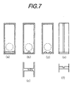
- FIG.7 shows various forms of the narrow passage 8: FIG.7(a) shows a most stable form employed in the embodiment describe above, formed over the entire width of the cartridge.
- FIG.7(b) and (c) illustrate a narrow passage formed in the limited width of the cartridge, and formed as a curved passage, which is effective in the case of a printer having a large size, and therefore is not always used in the normal printer.
- FIG.7(d) shows a plurality of passages formed as tunnels, which facilitates movement of the ink to the inner surface of the cartridge and provide centralized introduction of air which contributes the air-liquid replacement.
- FIG.7(e) and (f) shows another form of the passage, in which, in addition to the scheme in FIG.1, a groove is formed in the partition 5 over the vertical direction. Accordingly, the gas or air reached the lower edge of the partition is effectively introduced into the ink chamber 6 through this groove to improve the recovering efficiency of the ink.
- the position of the narrow passage 8 is determined in taking account of the position of the opening 3. That shown in FIG.6(a) is preferable in preventing ink leakage, because the edge of the partition 5 is lower than the lower end of the opening 8, and accordingly the ink retained in the material 3 is beneath the lower end of the opening 2. In contrast, that shown in FIG.6(b) is not preferable as less effective for preventing ink leakage, because the edge of the partition 5 is higher than the lower end of the opening 8, and accordingly the ink retained in the material 3 is above the lower end of the opening 2.
- the dimension of the narrow passage 8 is, in practice, selected from the range between 0.1 mm and 20 mm as the maximum range.
- the shape of the partition although any form is selected when taking into consideration of the opening 2, several examples are shown in FIGS.8(a) to (h).
- FIG.9(a) to FIG.(d) various forms for the structure of the interface between the partition 5 and negative pressure producing material 3 can be devised as shown in FIG.9.
- the material 3 is not compressed by the edge of the partition 5, the density of the material 3 is not locally raised, and circulation of the ink and air is relatively increased, therefore, this is preferable in the case of high speed recording or color recording.
- the material 3 is compressed by the edge of partition 5, and, although there can be a resistance against the air flow due to the increased density of the material 3, ink leakage or the like troubles due to a slight change of the environment can be prevented. Therefore, the selection thereof may be designed in consideration with the kind of the recorder or environmental conditions.
- the volume ratio of the chamber 4 and ink chamber 6 is determined in taking account of the kind of the recorder and environmental conditions. Also, the relation with the negative pressure producing material 3 is important. To increase the using efficiency of ink, the volume of the ink chamber 6 is preferably increased, wherein the material 3 producing a sufficient reduced pressure, such as having a increased compressibility as sponge, is effectively utilized. Therefore, when taking into consideration of increasing the ability of reduced pressure production of the material 3 in accordance with increasing the volume of ink chamber 6, the volume ratio between the chamber 4 and the ink chamber 6 may be a value in the range of 1:1 to 1:3 as the optimal range in practical use.
- the filter at the end of joint member 7, whose shape, dimension and mesh may be selected according to the kind of the ink jet recorder, is preferably selected as having a smaller mesh compared with the diameter of the orifice to prevent dusts likely to enter from the ink jet cartridge for preventing blinding of the nozzle of the recording head.
- the filling quantity of ink into the ink jet cartridge is not limited so long as in the range of ink jet cartridge capacity.
- the filling quantity of ink into the negative pressure producing chamber is set in the range not exceeding the limit of ink retaining ability of the negative pressure producing material 3.
- Such retaining ability is referred to the ability of negative pressure producing material 3 which is able to solely retain the ink when it is soaked with ink.
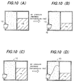
- ink jet cartridge having the tightly sealed ink chamber 6 in response to the external ambient changes, such as temperature rise or atmospheric descent, especially due to expansion of the air in the ink chamber (sometimes due to expansion of ink), the ink remaining in the chamber is likely to be pressed out to cause ink leakage.
- the ink remaining in the chamber is likely to be pressed out to cause ink leakage.
- another air outlet 10 is formed, in-addition to the opening 2, in the chamber 4 shown in FIG.10(c) and (d), and therefore, the ink moved into the chamber 3 due to the air expanded in the ink chamber is allowed to be introduced to the side of ambient air.
- the air outlet 10 may be positioned higher than the opening 2 of chamber 4, and more preferably, it may be, in addition, remote from the opening 3 in order to keep the ink flow, which occurs in the material 3 at a time of environmental changes, separate apart from the joint opening 2.
- the number and shape of the opening 10 may be free, but evaporation of ink is taken into consideration.
- seal materials for preparing evaporation of ink or expansion of air in the ink jet cartridge.
- seal materials may barrier materials, such as a single layer barrier material, or a composite barrier material, which is a composite material of multi-layer plastic films, or of such plastic films together with paper or cloth as reinforcement or with aluminum foil.
- the same material as that of the ink jet cartridge may be selected for the adhesive layer of the barrier and thermally fused for improve sealing ability.
- the packaging material may be selected also from the same material as that of the barrier material with taking account of gas penetration rate and air penetration rate.
- the material for the ink jet cartridge itself may be any of the conventional materials, but should be selected from those which would not affect or are treated so as not to affect the ink for use in the ink jet cartridge, also, productivity of ink jet cartridges will be considered.
- an ink jet cartridge is separated into the bottom part 11 and the upper part thereabove, each of these is separately molded with synthetic resin, the negative pressure producing material is filled, and then the bottom part and the upper part are fused to be secured with each other, thus an ink jet cartridge is manufactured.
- a transparent or translucent material as the synthetic resin to enable the ink within the ink chamber to be visually inspected, the time for the cartridge to be replaced is readily determined through visual inspection.
- a recessed portion may be provided. Further, preventing a crimp or the like on the outer surface of the ink jet cartridge may be preferable for design performance.
- a method of applying either increased or decreased pressure may be used for filling the ink.
- Providing an ink filling inlet for either the chamber or ink chamber of the ink jet cartridge may be also preferable, as the other ink jet cartridge would not be contaminated.
- the filling inlet may be sealed with plastic or metal material.
- the replaceable ink jet cartridge of the invention may be of any construction and configuration and variation which are freely selected in the scope of the invention. As discussed above, the invention provides a replaceable ink jet cartridge improved in provided with higher reliability at single transportation, with a simple construction and with ability of being inspected as to the remaining ink liquid.
- the suitable reduced pressure is maintained throughout the period ranging the initial use to the final use to meet with high speed recording, and a replaceable ink jet cartridge which is free from ink leakage even in any ambient conditions. Further, the cartridge is improved in handling facility, without incorporating ink leakage even at replacement, and no erroneous operation at the equipment into the ink jet recording apparatus.
- effect of the surfactant is utilized.
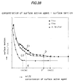
- c. m. c. The measurement of the critical micelle concentration (hereinafter, abbreviated "c. m. c.") is discussed below with reference to FIG.38.
- a set of ink samples were prepared, which contain the same composition, but each containing a surfactant (s.a.a.) having concentration different from each other, and each sample was measured as to the surface tension, by using a surface tension measuring apparatus, made by Kyowa kaimen Kagaku Kabushiki Kaisha, Trade Name: "Surface Tension Meter CBVP-A3".
- the c.m.c. was defined by the saturated value, that is, the minimum value of concentration, at which the gradually increased concentration of s.a.a. will not allow the surface tension to be further lowered.
- the same measurement was performed in the water, and the c.m.c. value at water was also obtained.
- a color developing agent such as dye or pigment is added in the ink, and various addition materials are also added, for purposes of increasing retainability and preventing adhesibility.
- the majority of these materials is diffused in the solution, and is present on the gas phase interface or liquid phase interface by a certain probability.
- the interface between liquid-gas and liquid-solid in the ink composition is in the condition different from that in the water, and is under the condition in which the color developer or addition materials are distributed on such interface.
- the concentration is allowed to reach the c.m.c.
- the surfactant in the course of orientation of the surfactant on the interface, the surfactant is oriented also on the surface of the dye and materials existing on the interface under the condition different from the water, and therefore the surface tension continuously descend. Also, the surfactant is partially absorbed and consumed by the dye or addition materials which are present in the solution.
- the surfactant is consumed to eliminate the ununiformity of the interface due to the presence of color developing agent or addition materials, and, for this reason, it is supposed that the c.m.c. in the composition would exceed the c.m.c. in the water.
- the extremely lowered surface tension in the case of the lower concentration is also caused as the same phenomenon as in the water.
- the added surfactant is solved in the solution and will be oriented on the dolor developing agent, and alternatively the surfactant will be oriented on the color developer or addition materials present on the surface and consumed.
- the surfactant is oriented on the gas-liquid interface and sufficiently achieves its function of lowering the surface tension.
- the lowered surface tension found in the case of ink composition with lower concentration of surfactant is attributed to the same mechanism as found in the water.
- the rate of descend of the surface tension is slowed down.
- Such a phenomenon is supposed to show the condition that the surfactant has been sufficiently oriented on the gas-liquid interface, and therefore the surface tension has been already generally decreased to almost the lowest limit.
- the behavior of the surface tension in the range from the curvature turning point to the point on which the surfactant, which becomes already unable to be oriented on the surface, is inevitably oriented on the surface of the color developer and addition materials, and, on the other hand, is also oriented on the color developer and addition materials, thus the ununiformity of the surface condition is eliminated. Based on such a process, it is supposed that the surface tension gradually decreases after passing over the curvature turning point.
- FIG.39 how the concentration of the surfactant will affect the printing quality is briefly shown in FIG.39.
- the "interface bleeding" is especially shown, which can provide the utmost affects on the printing quality.
- the surfactant of a concentration higher than the c.m.c. in water is present on the surface of the ink, the surfactant existing on the interface is assumed to be oriented. Therefore, as to preventing the bleeding defect, when the concentration of the surfactant is greater than the c.m.c.(w) in FIG.39, a sufficient effect is obtained.
- the viscosity of the ink is gradually increasing. This is especially remarkable when exceeding the c.m.c.(i) of the ink. This also proves the phenomenon which is discussed hereinbefore in the BACKGROUND as observed over the c.m.c.(i) of the ink. As has been discussed, the viscosity of ink which is increased by the concentration exceeding the c.m.c.(i) would cause degradation of the condition of the injected ink, and largely affect on the quality of the recorded images and on recovery of the ink jet cartridge.
- the point E at which the concentration of the surfactant is 1 wt %, is selected, where the points C1 and C2, which correspond to the ink A and B respectively, both exhibit the surface tension of greater than 30 dyn/cm and of the same concentration.
- the overall concentration is in the range less than the c.m.c. for ink plus c.m.c. for water. Accordingly, a color recorded image using only the ink A and B with the concentration corresponding respectively to C1 and C2 should be a preferred embodiment of the invention.
- the property after ink injection can be changed in the recording environment formed by controlled heating means at 200 C, and recording ability on the recording medium can be attained to that of over the c.m.c.(i) of the ink.
- Embodiments of the ink in use for ink jet recording are described hereinafter.
- Embodiment 1 Comparison 2 3
- Solvent glycerin 5.0 5.0 5.0 thiodiglycol 5.0 5.0 5.0
- Surfactants acetylene glycol ethylene oxide addition product (Trade name: Acetynol EH) 1.0 0.5 5.0
- Stabilizer urea 5.0 5.0 5.0
- Dyes black/ C.I. Feed black 2 4.0 4.0 4.0 Yellow/ C.I. Direct yellow 86 2.5 2.5 2.5 2.5 Cyane/ C.I. Direct blue 199 3.5 3.5 3.5 Magenta/ C.I. Direct red 227 3.0 3.0 3.0 Balance: water
- the ink used in Embodiment 1 has the composition featured by the invention: the concentration of the surfactant is not less than the c.m.c. in purified water, and not exceed the c.m.c. in the ink.
- Each Comparison ink was used as an object for showing the effect of the invention, wherein the concentration of the surfactant is less than the c.m.c. in purified water for Comparison 1, and less than the c.m.c. in the above ink composition for Comparison 2.
- the ink was evaluated for interface bleeding, the possible time to be kept unused and so on.
- the copying paper Canon NP dry paper was used.
- a printer a color ink jet printer, trade name: Canon BJC-820J, in which the ink is injected by way of thermal bubbling, was used.
- the colors were selected such that: one from the group of black, cyan, mazenta and yellow; and the other from that including cyan, mazenta and yellow.
- the ink in this Embodiment 2 and thereafter are those which contain a surface active agent in the following manner: that, using a surface active agent, whose content is extremely near the c.m.c. of the ink, the ink is condensed by evaporation of the solvent or water during the ink flying or process of fixing, accordingly, the concentration of the surface active agent in the ink turns to exceed the c.m.c. in the ink. Thereby, it is advantageous that the ink still maintained in the head may be treated as containing the surface active agent in the amount of not exceeding the c.m.c. in the ink. Further, in the osmotic step of ink, the concentraion has already become to exceed the c.m.c. in the ink , the defect of bleeding or the like is prevented to improve the dot quality.
- FIG.44 diagramatically illustrates how the concentration of the surface active agent changes.
- FIG.46 shows the injection property of the head. As found by FIG.46, as the concentration of surfactant increases, the decrease of surface tension and increase of viscosity cause the refill frequency to be rapidly lowered. Under the concentration Cc.m.c. also, the decrease of refill frequency is obserbed due to the increased viscosity, when the concentration of surfactant is increased.
- Refill of ink for the nozzle under printing was determined based on printing condition.
- the c.m.c. in ink of the surface active agent employed is low, and the change in the course from below to above the c.m.c. in the ink is extremely remarkably found. Therefore, it is possible that the conversion from below to above the c.m.c. in the ink can be within the time until reaching the medium surface and only by evaporation of water content from the surface, and therefore, advatageously, not any supplemental sovlent is necessary.
- Embodiment 3 for increasing evaporation of water content and low boiling point sovent, the temperature is conditioned and raised in the head. Evaporation of water content advances in the same manner as Embodiment 2, but the c.m.c. of the surface active agent emp loyed here is higher. In this case, it is no longer possible to completey achieve the conversion from below to above the c.m.c. in the ink within the time until reaching the medium surface and by evaporation of water content from the surface. For this reason, isopropyl alcohol which is of low boiling point is added to accelerate condensation.
- ink drops at the time of reaching the medium surface, owing to evaporation of water and low temperature solvent by heating as well as the rapid change of surface condition due to injection and arrival of drops, ink drops, at the time of their arrival at the surface, are in the unstable condition of a solution, such that the surface active agent-water system which exists in the interior and on the boundary surface has not yet reached the equiliblium condition. Therefore, such an ink is supposed to have no osmotic ability which an ink should originally have. Starting from such a transient state, the solvent having low boiling point is continued to evaporate from the ink, and concentration of the surface active agent increases. After arriving at the medium, the ink reaches over c.m.c., and its osmotic ability is increased.
- solvents which may behave as a surface active agents, increase viscosity, and lower the surface tension. These solvents are not preferable, as these will affect the behavior of ink in the head.
- the most preferable solvents are those which would raise the viscosity but in only a few extent, and lower the surface tension but at only a few extent.
- Embodiment 3 Comparison 4 5
- Solvent glycerin 5.0 5.0 5.0 thiodiglycol 7.5 7.5 7.5
- Low boiling point solvent isopropyl alcohol 5.0 5.0 0.0
- Stabilizer urea 7.5 7.5 7.5
- surfactants acetylene glycol ethylene oxide addition compound (Trade name: Acetynol EH) 1.9 4.0 1.9
- Dyes black/ C.I. Feed black 2 3.8 3.8 3.8 Yellow/ C.I. Direct yellow 86 2.5 2.5 2.5 2.5 2.5 Cyane/ C.I. Direct blue 199 3.5 3.5 3.5 Magenta/ C.I. Direct red 227 3.5 3.5 -3.5
- Balance water
- TABLE-2 shows the results of bleeding and refill frequency tests simmilarly with Embodiment 2.
- Comparison 4 is listed, added with over the c.m.c. of surface active agent. As shown, in Comparison 4, refill is not in time at 5 kHz, while refill property is good even at 6.0 kHz in Embodiment 3.
- FIG.11 is a sectional view of an ink tank, comprising a body enclosing a minor partition 61 and a partition 5.
- An absorbing member 3 as a reduced pressure creating member is filled in a section having a opening 2, and a bottom plate or closure 11 is attached.
- FIG.11 further shows a recording head HD connected to the ink cartridge.
- the ink cartridge 1 is enclosed by attaching a bottom plate 11, at the same time, a narrow passage 8 is formed between the edge of partition 8 and bottom plate 11, and an air communication outlet 10 is formed on the same wall where the opening 2 is formed.
- Recording head HD is connected through a joint member 7 to the ink cartridge.
- Joint member 7 has its inner end inclined so that the upper side thereof extends ahead.
- the ink passage within the joint member is shaped as a horn opened upwardly, which enables to adequately introduce the ink from the absorber to the head.
- the ink jet recorder is constructed in the form, in which is provided with a heating element 72 for generating thermal energy utilized to inject the ink from the injecting hole 71 of nozzle 73, and a recording head HD is of the form to cause a phase transition of the ink by thermal energy. Further, by the stabilized performance of ink supplement, recording with high density and high precision is achieved especially in color recording.
- the invention provides a replaceable ink cartridge with high reliability at its single conveyance, a simple construction, and also with ability of detecting the remaining ink in the ink cartridge.
- a suitable reduced pressure that is, the lowered pressure is maintained in the ink cartridge, which contributes to perform the high speed recording, especially preventing ink leakage.
- the ink cartridge is also provided with handling facility, and would not incorporate ink leakage also at replacement of the ink cartridge.
- the reduced pressure creating reservoir 4 and ink reservoir 6, in communication with each other through a narrow passage 8, are integrally formed.
- Ink is fed from an opening 13 of bottom plate 11. After being filled in reservoir 6, the ink is fed to the relatively a greater part of the reduced pressure creating member 4.
- the reduced pressure creating member 4 has the area adjacent the air outlet 10, which is kept without being fed with ink. Thereafter, the opening 13 is sealed by a ball 14, and opening 2 and air outlet 10 are also sealed with tha same or different seal member.
- FIG.12 shows the ink cartridge ready to operation, where the ink reservoir 6 is filled with ink, and schematically shows the printer for use.
- the area 3A adjacent the outlet 10 is formed as the area maintaining no ink, and area 3B for creating a reduced pressure is compressible and deformable by insertion of a ink supply tube, not shown.
- the rest area is left as that maintains the ink which is fed.
- the area 3B faces the opening 2 formed below the outlet 10, and opening 2 is positioned higher than the narrow passage 8 for fulfill the feature described above.
- the area 3A still maintains no ink , therby causing no leakage of ink regardless of vibration or change of pressure.
- the area adjacent the air outlet 10 having no ink, ink leakage from the air outlet is prevented in any change of ambient conditions.
- the outlet 10 is sealed with a seal member, there is further effect to prevent pealing off of such seal member.
- this area produces another effect to feed air as necessary to prevent the change of the reduced pressure in the ink cartridge.
- the area adjacent the outlet 10 may be out of wet with ink, which contributes to further decrease the osmotic speed of the ink. Alternatively, it may be also formed as the area which is wet with ink in advance, which ink is afterwardly removed.
- the ink supply opening 2 or the compressible are positioned, thereby the ink in the second reservoir 6 be ing provided with a stable passage in the reduced pressure creating member.
- the ink supply opening 2 may be pleced higher than narrow passage 8, the ffect of which is to fix the ink feed direction, and to completely utilize the ink in second reservoir 6.
- the air in the second reservoir 6 can be in the state as retained but may be moved toward the opening 2.
- ink in the reduced pressure creating member 3 can be utilized to minimize the rest ink that is left unused.
- the one -direction ink passage mentioned above is formed in the area 3B, and by the ability of ink maintaining of the area 3A, the quantiti of unused ink is further minimized.
- the printer of the invention is equipped with a head recovery device HR, which automatically or manually perform feeding out of the ink from the cartridge through the head by means of aspiration or injection.
- HR head recovery device
- FIG.12 shows the tank 1 in which the seal tape is removed form the cartridge 1 in FIG.1.
- the tank is mounted on the carriage, wherein the supply tube of the head passes through the opening 2, and the reduced pressure creating member 3 is compressed and deformed at its compressible are 3B.
- the member 3 is deformed toward the narrow passage 8.
- an detection device not shown, as known device mechanically or electrically detecting the status of being connected or separated
- an informing signal informing that the ink cartridge has been just equipped is produced and applied to the control unit CC. According the signal, before atarting printing operation, the head recovery device HR is operated to remove the ink out of the tank to improve the condition of ink in the tank.
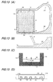
- FIG.13(A) shows another embodiment of the ink cartridge with a modified internal structure of ink reservoir, in which an upwardly enlarged area 22 is supplemented.
- the inner surface 20 is formed to be as gradually raised as it is remote from the passage 8, and is formed so that even minute ink drops produced due to the surface tension of ink are fedtoward the reduced pressure creating member 3, upwardly extending area 21 serves as the finger holder for the operater to prevent deformation of the tank caused at its handling.
- FIG.13(B) shows the similar tank and the end of partition 51 which inclines and allows the volume of the ink reservoir 6 to enlarge, but allows that of the reservoir 4 to reduce.
- FIG.13(C) shows the bottom plate 11, which forms a narrow passage 8 between the partitaion 5, and which is interposed between the side walls 101 and 100 and secured.
- the symbol SE represents the edge of partition 5. If there is any dipersion in the status of adhesion fixing, the space SP is of indefinite width. Shown in FIG.13(D), the spacers 110 may be placed on both ends, respectively, and be on the surface of bottom plate 11. Further, recesses 30 positioned within the space SP may be formed on the bottom plate 11, thereby increasing recovering ability of air introduced into reservoir 6.
- FIG.14(A) and (B) show the inclinable range of the ink cartridge, the numeral 40 being the horizontal surface.
- the narrow passage 8 is preferably in a lowered position, and most preferably be in parallel with the surface 40 under the ink cartridge.
- the angle ⁇ may be within 0 ⁇ ⁇ ⁇ 15 When conveyed on a scanning type carriage, it may be within 0 ⁇ ⁇ ⁇ 5 .
- the reduced pressure creating member 3 may be of a plurality of members, where the boundaries therebetween can cause the movement of air there to produce a trouble. There fore, it is more preferably of single porous material.
- any which maintains relatively more ink than reservoir 4 may be included as an ink reservoir.
- the weight produced when the user grips the cartridge, or the deformed external surface due to environmental change during conveyance will cause leakage of ink either from the orifice of the head, or form the air outlet 10 formed for correcting the pressure in the cartridge as the atmosphere.
- Embodiment described below is an ink cartridge for use in the ink jet recording, improved for preventing ink leakage due to the external force during handling or conveyance, and due to the environmental change such as of temperature or atmospheric pressure, and further improved in higher efficiency of ink using.
- the ink cartridge body comprises an opening 2 to be connected to the recording head, an air outlet 10 provide higher than opening 2 for introducing the air, a first reservoir 4 for enclosing a reduced pressure creating member, and an ink reservoir 6 adjacent the reservoir 4.
- the reservoirs 4 and 6 are in communication with each other via a narrow passage 8, and a partition 61 leaves a space therebelow wider than the partition 8.
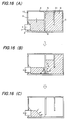
- FIG.16(A) especially shows a joint member 7, inserted into the opening 2 to pressurize the reduced pressure creating member 3, and the ink jet recorder is now ready to operate.
- a filter for screening dusts in the ink cartridge On the end of joint member 7, a filter for screening dusts in the ink cartridge.
- a plurality of partitions 61 may be formed in the reservoir 6 as shown in FIG.18.
- Embodiment it is constructed so that the displacement of each side walls 12a, 12b and 12c of reservoirs 4 and 6 against the foreign force is in the same order.
- the side wall 12a is formed thicker than that of side walls 12b and 12c, and ribs 61 are formed in the positions so as to divide in same volume of sections.
- the cartridge is formed so that the amount ⁇ t6 of deformation per unit area is minimum, and further the change of side walls are of the same order. Also, the change of the reservoir 4 is designed to be in the same order, to prevent leakage of ink.
- the ink cartridge shown in FIG.15(B), formed of poly propylene, has the external dimension of 48 mm in length, 35 mm in height, and 11 mm in thickness. In the middle of the entire span of 48 mm, each thickness is : that of side 12a is 1.5 mm, that of 12b and 12c is 1mm each, and the rib 61 is positioned from approximately 10 mm from each wall.
- the numbmer or dimension of the partitions 61 may be otherwise selected in accordance with the number or dimension of the ribs.
- FIG.20 shows the relationship between the thickness of each wall and ink leakage at handling and conveyance, which is examined in order to determine the wall thickness of reservoirs 4 and 6,
- the inceased thickness contributes the increase of strength. In order to satisfy the small-sized and higher utility of ink, less thickness to increase the internal volume is necessary. From the data in FIG.20, it has been selected, 1.5 mm wall thickness for reservoir 4, and 1.0 mm for reservoir 6.
- the thickness ratio is that: the wall thickness of reservoir 4 relative to that of reservoir 6 may be 1.2 to 3.
- the invention is applied for color recording of single color, and also excellent for minimize tha printer using a plurality of color inks, and also provides a long period of replacement cycle.
- FIG.33 shows the ease of replacement procedure.
- the Embodiment After sufficiently connecting the replaceable tank with recording head and urging the replaceable ink tank, therefore, positioning between the carriage and the head is simply performed.
- the replacement procedure can be facilitated.
- the electric connection betwwen the carriage (recorder body itself) and the head is completed, and operation ability is also excellent.
- the electric connection may be of a separate connection form to ensure the head positioning and connection with the replaceable ink tank.
- the recording medium p is horizontally transported by the Platen Roller 5000, and pressed onto the Platen Roller 5000 by Paper Retainer 5000 over the carriage moving direction.
- a carriage movement pin is fitted with the spiral groove, is supported and engaged with the lead screw 5000 and slider 5003, and is moved front and back along the recording surface of the medium guided on the Platen Roller 5000.
- Lead Screw 500 5 is driven to rotate with the alternating rotation of drive motor via drive transmission gear means.
- An image recording signal is fed to recording head 2010 in timing with the movement of carriage HS on which the head is mounted and let the ink drop inject at the specified position.
- the ink tank and ink is especially suitable for longuitudinal printing attitude, in which recording medium P is faced on the lower surface of the recording head 2010 and perform the recording scanning, and the medium P, without being rolled on the platen roller, can be supplied, printed and discharged almost on the same surface, to be suitable for printing on thick paper such as OHP paper.
- the ink tank 2001 is higher than the injecting area of the head 2010, therefore, it is necessary to support the water head corresponding to the above quantity, and to maintain the inner pressure of ink at slightly increased pressure, preferably slightly reduced pressure to stabilize the meniscus of the ink at the injecting area.
- the recorder in FIG.33 is also referred in the Embodiments described below.
- FIG.21 and FIG.22 show sectional views of an ink cartridge body, and FIG.23 shows the upper surface of the partition.
- an air inlet groove 1031 and reduced pressure creating member adjusting section 1032 are formed in the part of partition 1003 which is the partition between ink reservoir 1006 and pressed member reservoir 1004.
- the air inlet groove 1031 is, ranging from the middle area of partition 1005 to the edge of parition 1005, namely to narrow passage 1008 with the cartridge bottom 1011, formed on the side of reduced pressure creating member reservoir 1004. And, between the area of the member 1003 which engages the area of air inlet 1031 of partition 1005, a recessed area of adjusting section 1032 for reduced pressure creating member is formed.
- the engaging force of the member 1003 is partially relaxed, as shown in FIG.21 and FIG.22. Namely, as the ink begins to be consumed from the head, the ink soaked in the member 1003 is comsumed, and reaches the adjusting section 1032. As the ink further continues to be consumed, from the area where the engaging force of the member 1003 is relaxed by the adjusting section 1032, the air tends to break the meniscus, so the air is rapidly introduced into the groove 1031 and the reduced pressure control is facilitated.
- a elastic porous material may be used as the reduced pressure creating member.
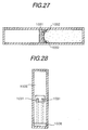
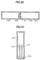
- FIG.29 to FIG.31 show a Comparison provided without reduced pressure creating member adjunsting section.
- the condition is reached, wherein the member 1003 penetrates in the air inlet groove 1031. Accordingly, at engaging are a A, compressive force of the member 1003 is not relaxed, air will hardly break the meniscus there, and is difficult to enter the groove 1031. Thus, even the ink continues to be consumed, air-liquid exchange is not performed, the merit of air inlet is not developed, ink of ink absorbing area 1006 is not used, and turns to be non-operable.
- the Embodiment is provided with the excellent effect than the Comparison.
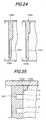
- FIG.24 shows a partition in another Embodiment having two different sectional shape.
- FIG.25 shows an enlarged section of the partition.
- the shape of air inlet 1031 and adjusting section 1032 is different from the ink cartridge shown before.
- the stepped portion of partition 1005 engaging the member 1003 is chamfered R for increasing relaxation of pressure and compression.
- section 1032 may be freely selected.
- the inner surface is divided in two ink reservoirs (a, b) which is communicated along the bottom, the ink controlled as to capillary force is filled, and air passage 2013 is provided.
- ink in FIG.34 is a half consumed state converted from the initial filled state.
- ink in the compressed ink absorber is maintained in the level in which the water head from the inject openig, the reduced pressure in the ink chamber 2006 and the capillary in the ink absorber are balanced to each other.
- quantity in ink chamber 1004 does not reduce and ink in the chamber 2006 is consumed.
- the ink distribution in chamber 2004 is as maintained in equilibrium, ink which meet with the ink supply is consumed, and air is introduced as the amount corresponding to the consumed quantity of ink.
- the exchange is performed between air and ink at the lower end of the ink chamber 2005,
- the meniscus formed in the comressible ink absorber of ink chamber a 2004 is partially broken, and air is introduced so that pressure in the ink chamber b 2006 is balanced with the meniscus preserving ability of the compressed ink absorber.
- FIG.36 the principle of ink supply and production of internal ink pressue is further discussed.
- the ink absorber 2003 adjacent the ink chamber is, as communicated with air passage 2013 in the status the ink is consumed for a predetermined amount, to form a meniscus against-the atmpspheric pressure.
- the air space has its inner pressure reduced such that it is balanced with capillary force of the compressible ink absorber 2003 and the water head of ink remaining in ink chamber 2006, and it maintains the meniscus formed by compressible ink absorber 2003. From such a condition, when ink is supplied in the recording head via ink supply area, ink flows out of ink chamber b and accordingly the pressure in ink chamber b further reduces. In parallel thereto, the meniscus formed in the compressed ink absorber below the wall of ink chamber 2005 is partially broken, and air is introduced such that the excessively reduced pressure of ink chamber b 2006 is balanced with the meniscus maintaining force and the water head of ink itself in the ink chamber b 2006. Namely, the internal pressure of the ink supply area is maintained for a predetermined pressure by way of the capillary force of the compressed ink absorber adjacent the lower end of the wall of the ink chamber.
- FIG.34 is to explain the function of the compressible absorber as a buffer absorber, and shows the condition of ink, which has just flown out of chamber b 2006 toward the chamber a 2004, due to descent of the atmospheric pressure or air expansion in the chamber b 2006 owing to temperature rise.
- the ink flowing into ink chamber a 2004 is adapted to be maintained by means of compressible absorber 2003.
- the maximum absorbing quantity of ink chamber a 2004 may be determined in view of preventing ink leakage as mentioned above, and it is preferable to provide the ink chamber a with at least a volume sufficient for enclosing the absorber.
- the interval pressure becomes slightly positive, but less affects on the injection property.
- the problem above occurs, for example, when the recorder employed under lowered atmosphere is turned to use under normal atmospheric pressure. Even in such a case, only introduction of air into ink chamber b 2006 occurs. Also, being turned to the use at higher altitude again, the internal ink pressure is only slightly raised. The use under the pressure extremely higher than the standard atmosphere is much less be expected. Therefore, there are no serious problems in practical use. From the initial use to just before replacement of the ink tank, the ink in the chamber a 2004 is steadily retained by means of the ink absorber 2003 in the ink chamber a 2004. Also, the chamber b 2006 is closed, and there is caused no leakage of ink out of air in let and ink supply area, thereby handling being improved.
- the maximum ink absorption capacity of ink chamber a 2004 is determined in taking account of ink leakage from the ink chamber b 2006 under worst condition, as well as the ink quantity to be maintained in the ink chamber a 2004.
- the ink chamber a 2004 may by provided with a capacity which is necessary for accommodate the ink absorber 2003 in taking account of ink absorption rate of the material of ink absorber 2003.
- the first requirement is that the dimension thereof is in the extent not to allow the meniscus to be formed in the passage.
- the opening may be provided with a dimension capable of performing smooth gas-liquid exchange.
- the internal pressure may be set so as not to affect the ink injection property of the recording head.
- the internal ink pressure of the ink supply area is maintained by the ink absorber 2003 adjacent the wall of ink chamber. Therefore, in order to maintain the desired pressure at the time to supply ink from the ink clamber b 2006, the adjustment of capillary force of the absorber 2003 adjacent the lower end of the wall 2005. Namely, the compressibility and initial pore size of the absorber 2003.
- the portion of the ink absorber 2003 positioned near the lower end of wall 2005 may exhibit a capillary force capable of raising the level the ink for h mm.
- the height of gas-liquid boundary (i mm) may be higher than that of the air supply area.
- the boundary is gradually lowered in the direction toward inside. In other words, ink lifting force gradually reduces.
- capillary force may be let small only adjacent the wall 2005.
- capillary force provided by the absorber 2003 is set as gradually increases as the ink supply area is approached, accordingly reaches maximum at the supply area (pore radius: P5).
- symbols A351, A361 and A371 represent gas-liquid interfaces
- arrows A352, A362 and A372 indicate that the complessibility changes from small to large.
- ink is to be stable against vibration and the interface would be stable against environmental changes.
- water soluble organic solvents are those with low volatality, low viscosity and not attack the humans listed below:
- Amides such as: dimethyl formamide, or dimethyl acetoamide ketones such as: acetone; ethers such as: tetrahydrofrane, or dioxane; polyalkylene glycols such as: polyethylene glycol, or polypropyrene glycol; alkylene glycols such as: ethylene glycol, propylene, butylene, or triethylene; alkylene glycols such as: hexane triol, thiodiglycol, hexylene diglycol, or diethylene diglycol; lower alkyl ethers of polyvalent alcohols such as: ethyleneglycol methyl ether, diethyleneglycol monomethyl ether, or triethyleneglycol monomethyl ether; monovalent alcohols such as: ethanol, isopropyl alcohol; also, including glycerin, N-methyl-2-pyrolydone, 1, 3-di
- surfactants are useful in the present invention.
- surfactants include: salts of fatty acids, sulfuric ester salts of higher alcohols, alkylbenzene sulfonic salts, anion surfactants such as higher alcoholic phosphoric esters, fatty amine salts, cathion surfactants such as quarternary ammonium salts, higher alcohol ethylene oxide addition products, alkyl phenol ethylene oxide addition products, fatty acid ethylene oxide addition products, poly alcoholic fatty acid ester ethylene oxide addition products, higher alkyl amine ethylene oxide addition products, fatty acid amide ethylene oxide addition products, polypropylene glycol ethylene oxide addition products, fatty acid esters of higher alcohols, non-ionic surfactants such as fatty acid amides of alkanol amines, and surfactants such as of amino acid type or betaine type.
- FIG. 47 & 48 A general construction in the embodiment 4 in which the similar ink is used as in the form in embodiment 2, is shown in FIG. 47 & 48.
- the heater 109 or the fan 111 for the heater 109 equipped in the printed area make the atmosphere about the printed & settled area dry, and assist the evaporate the solvent and water etc.
- the slope of the curve in FIG. 44 is getting sharp and the concentration is accelerated so that the time of absorption period t2 shown in FIG. 44 is shortened.
- the printed paper is also kept in dried condition, absorption of the solvent in the paper is accelerated and the speed of evaporation and settlement are accelerated.
- multi-scan printing technique which print one print unit by using different nozzles, in order to prevent the variation of ink jet volume and direction, is used in general.
- one jet volume per unit area is fewer than usual. This is very advantageous for evaporation of the solvent and water, when the similar ink is used as in the embodiment 2 or 3.
- the rate of bleeding is rather larger by its good permeability, and the ink quantity to cover the predetermined area is lesser than the ordinary ink.
- FIG. 41 shows the printing method of the embodiment 8.
- the same ink jet printing apparatus and the same ink jet head are as those used in embodiment 1.
- recording area (L) of the ink jet head is divided into four parts.
- first scan 25% part then the paper is fed by the width of L/4.
- second scan another 25% part is printed by using other nozzles as those used in the first scan, then the paper is fed by the width of L/4.
- third scan another 25% part area is printed, then the paper is fed by the width of L/4.
- forth scan another 25% part is printed, then the printing is finished.
- FIG. 40(d) shows an example of the method of 25% thinning, the positions and the order of the ink spotting are showed in number.
- the printing at 1 is operated in the first scan, the printing at 2 in the second scan, the printing at 3 in the third scan, the printing at 4 in the forth scan, through these process the printing in an area is finished.
- the printing on the recording area (1) is operated by using nozzles in the first scan.
- the printing is operated in the condition of 25% thinning by using K(black), C(cyan), M(magenta), Y(yellow), head.
- the positions 1 in FIG. 40 is printed, they are described as K1, C1, M1, Y1, in FIG. 41.
- the paper is fed by the width of L/4.
- the printing on the recording area (1), (2) is operated in the second scan.
- the printing is operated in the condition of 25% thinning.
- the positions 2 in FIG. 40. is printed; they are described as K2, C2, M2, Y2, in FIG. 41.
- the paper is fed by the width of L/4.
- the printing on the recording area (1), (2), (3) is operated in the third scan.
- the printing is operated in the condition of 25% thinning.
- the positions 3 is printed, they are described as K3, C3, M3, Y3 in FIG. 41.
- the paper is fed by the width of L/4.
- the printing is operated in the condition of 25% thinning.
- the positions 4 is printed; they are described as K4, C4, M4, Y4, in FIG. 41.
- the printing on the printing area (4) is finished.
- the paper is fed by the width of L/4, the same process as that mentioned above will be repeated.
- ink bleeding may not be happened, because the amount of ink spotting is restrained compared with that of embodiment 1 and 2.
- the color of black can be deeper, because the amount of black ink spotted is twice as much as that in usual.
- the printing can be operated without ink bleeding, because the amount of ink spotted from the nozzles in one scan is less than that causing overflowing ink.
- the irregularity of ink thickness may decrease, because each nozzles used in the first, second, third, and forth scan is different.
- the recording by the K(black) head same as that by other heads in the condition of 25% thinning requires twice as much recording time as that by other heads, because the times of scanning need to be twice as many as that in usual in order to spot the ink twice as much as that in usual.
- the interval of scanning from the end of the first scan to the beginning of the second scan must be longer than usual.
- the more times the scan is carried out the longer the recording time requires in order to wait longer in each scan because of the waiting time. Therefore, it is effective that the thinning rate is changed and the times of scanning decrease half when the amount of black ink is to be spotted twice as much as that in usual.
- FIG. 42 shows the construction of a printer when the printing on paper by using above mentioned multi-head.
- 101 is an ink jet cartridge.
- This cartridge has four color tanks and multi-head 102. Each tank is filled with black, cyan, magenta, yellow ink respectively.
- FIG. 43(a) shows an exploded view of the multi-head and an view of the nozzles arranged on the multi-head, 211 are nozzles arranged on multi-head 102.
- nozzles 211 are arranged parallel with Y axis, they may have slope. In this case, the printing is operated with the time lag, while the head moves in the direction X.
- FIG. 42 shows the construction of a printer when the printing on paper by using above mentioned multi-head.
- 101 is an ink jet cartridge.
- This cartridge has four color tanks and multi-head 102. Each tank is filled with black, cyan, magenta, yellow ink respectively.
- FIG. 43(a) shows an exploded view of the multi-head and an view of
- 103 is a paper feeding roller, which feeds the paper 107 in the direction Y by rolling while press the paper 107 with supplement roller 104.
- 105 is a paper feeding roller, which feeds the paper 107 and press the paper 107 like rollers 103 and 104.
- 106 is a carriage, which holds the four ink jet cartridge and moves them with printing.
- the cartridge is to be at home position, when printing is not operated or recovery process of multi-head is operated.
- FIG. 45. shows the shape of the reverse side of the top board.
- the carriage which is at home position before printing moves in the direction X when a printing operation occurs, then the printing is operated by the width of D on the paper by spotting ink from the, nozzles 211 on the multi-head 102.
- the a moves back to home position after the printing to the end of the paper, then the printing in the direction X will be operated again.
- the printing is operated in the direction -X.
- the paper feeding roller 103 feed the paper in the direction Y by the width of K. The repeat of the printing and the feeding paper by the width of K in each scan makes the printing on a sheet of paper complete.
- the color printing is operated by using two or more heads like FIG.42.
- different colors are printed to the adjacent pixel in the same or close scanning.
- the time between the arrival of a ink drop and the arrival of another ink drop is especially short, in the case that different colors are printed to the adjacent pixel in the same scanning. If the time the ink fix to the paper is longer than the time between the arrival of a ink drop and the arrival of another ink drop, the quality of picture will decline. If the time the ink fix to the paper is late in case of the close scanning, the quality of picture will decline because of ink bleeding. Therefore, it is understood that the fundamental construction of the present invention is effective.
- the concentration of surfactant in the ink is not exceeding critical micelle concentration in the ink, but become exceeding it, because the water and the solvent in the ink vapors, and the paper absorbs the solvent, in the time between the arrival of a ink drop and the arrival of another ink drop.
- the concentration of surfactant in the ink is less than critical micelle concentration in the ink but more than 80% of that, more preferable 90 to 99%.
- Ink which contains surfactant in the amount of not exceeding the critical micelle concentration in the ink but exceeding the critical micelle concentration in purified water, is filled into a cartridge, comprising a first chamber which encloses a negative pressure producing material, and a second chamber in communication with said first chamber only through a narrow passage Then, said ink is supplied to ink jet head and printed.
Landscapes
- Ink Jet (AREA)
- Inks, Pencil-Leads, Or Crayons (AREA)
- Ink Jet Recording Methods And Recording Media Thereof (AREA)
Applications Claiming Priority (3)
| Application Number | Priority Date | Filing Date | Title |
|---|---|---|---|
| JP24564093 | 1993-09-30 | ||
| JP245640/93 | 1993-09-30 | ||
| JP24564093A JP3238805B2 (ja) | 1993-09-30 | 1993-09-30 | インクタンク、インクジェット用カートリッジ及びインクジェット記録方法 |
Publications (3)
| Publication Number | Publication Date |
|---|---|
| EP0646465A2 true EP0646465A2 (fr) | 1995-04-05 |
| EP0646465A3 EP0646465A3 (fr) | 1995-08-23 |
| EP0646465B1 EP0646465B1 (fr) | 1999-07-28 |
Family
ID=17136667
Family Applications (1)
| Application Number | Title | Priority Date | Filing Date |
|---|---|---|---|
| EP19940115375 Expired - Lifetime EP0646465B1 (fr) | 1993-09-30 | 1994-09-29 | Encre pour cartouche à jet d'encre et méthode d'enregistrement à jet d'encre l'utilisant |
Country Status (4)
| Country | Link |
|---|---|
| US (1) | US6164772A (fr) |
| EP (1) | EP0646465B1 (fr) |
| JP (1) | JP3238805B2 (fr) |
| DE (1) | DE69419684T2 (fr) |
Cited By (11)
| Publication number | Priority date | Publication date | Assignee | Title |
|---|---|---|---|---|
| GB2293142A (en) * | 1994-09-16 | 1996-03-20 | Seiko Epson Corp | Capillary regulation of ink flow in multi-chambered ink cartridge for ink jet printer. |
| EP0765756A3 (fr) * | 1995-09-29 | 1997-11-12 | Canon Kabushiki Kaisha | Cartouche de réservoir d'encre, méthode de fabrication de celle-ci et structure d'emballage de la cartouche de réservoir d'encre |
| EP0860286A3 (fr) * | 1997-02-19 | 1998-10-28 | Canon Kabushiki Kaisha | Récipient pour liquides pour tête à jet d'encre |
| EP0845362A3 (fr) * | 1996-11-15 | 1999-06-16 | Canon Kabushiki Kaisha | Récipient pour distribuer un liquide |
| EP1020293A1 (fr) * | 1999-01-12 | 2000-07-19 | Hewlett-Packard Company | Cartouche a jet d'encre pourvue d'un reservoir d'encre libre et d'un reservoir rempli de mousse |
| US6145974A (en) * | 1983-10-13 | 2000-11-14 | Seiko Epson Corporation | Ink-supplied printer head and ink container |
| AU741182B2 (en) * | 1995-09-29 | 2001-11-22 | Canon Kabushiki Kaisha | An ink tank cartridge, a manufacturing method thereof and a packaging structure of the ink tank cartridge |
| EP1211080A3 (fr) * | 2000-11-29 | 2003-09-03 | Canon Kabushiki Kaisha | Encre, encre pour l'enregistrement par jet d'encre, réservoir d'encre, cartouche d'enregistrement à jet d'encre, système d'alimentation en encre, procédé d'introduction d'encre dans un réservoir d'encre, dispositif d'enregistrement d'image |
| US6674523B2 (en) | 2000-07-27 | 2004-01-06 | Canon Kabushiki Kaisha | Pre-viewing inspection method for article and device therefor |
| EP2540510A3 (fr) * | 2011-06-30 | 2013-07-10 | Mimaki Engineering Co., Ltd. | Appareil d'enregistrement à jet d'encre |
| US10974513B2 (en) | 2017-07-06 | 2021-04-13 | Hewlett-Packard Development Company, L.P. | Ink supply |
Families Citing this family (21)
| Publication number | Priority date | Publication date | Assignee | Title |
|---|---|---|---|---|
| US6474798B1 (en) | 1984-10-11 | 2002-11-05 | Seiko Epson Corporation | Ink supplied printer head and ink container |
| US6238042B1 (en) | 1994-09-16 | 2001-05-29 | Seiko Epson Corporation | Ink cartridge for ink jet printer and method of charging ink into said cartridge |
| JP2964930B2 (ja) * | 1995-10-18 | 1999-10-18 | 富士ゼロックス株式会社 | インクジェット記録用インク及びインクジェット記録方法 |
| SG100699A1 (en) * | 1998-05-13 | 2003-12-26 | Seiko Epson Corp | Ink cartridge for ink-jet printing apparatus |
| US6312121B1 (en) * | 1998-09-11 | 2001-11-06 | Xerox Corporation | Ink jet printing process |
| US6732414B2 (en) * | 1999-12-27 | 2004-05-11 | Seiko Epson Corporation | Method of manufacturing a liquid ink jet head |
| US20040155925A1 (en) * | 2003-02-06 | 2004-08-12 | Zerza Wendy L. | Printing apparatus |
| JP4812078B2 (ja) | 2004-12-28 | 2011-11-09 | キヤノン株式会社 | インクジェット記録装置 |
| JP2006212787A (ja) | 2005-02-01 | 2006-08-17 | Canon Inc | インクジェット記録装置 |
| US7666255B2 (en) * | 2005-03-09 | 2010-02-23 | Hewlett-Packard Development Company, L.P. | Ink-jet inks having surfactants below the critical micelle concentration and associated methods |
| CN201002388Y (zh) | 2007-02-24 | 2008-01-09 | 珠海天威技术开发有限公司 | 喷墨打印机用墨水容器 |
| JP5388817B2 (ja) * | 2008-12-12 | 2014-01-15 | キヤノン株式会社 | 液体吐出ヘッドの製造方法 |
| JP6230231B2 (ja) * | 2012-12-28 | 2017-11-15 | キヤノン株式会社 | インクタンク |
| JP5944947B2 (ja) | 2013-08-09 | 2016-07-05 | キヤノンファインテック株式会社 | 転写体および記録物の製造方法 |
| US9789705B2 (en) | 2015-04-24 | 2017-10-17 | Canon Kabushiki Kaisha | Ink jet recording method |
| BR112018008537A2 (pt) * | 2015-10-28 | 2018-10-30 | Hewlett Packard Development Co | cartucho de impressora com múltiplas câmaras de fluido em comunicação fluida |
| JP7392359B2 (ja) | 2019-09-30 | 2023-12-06 | セイコーエプソン株式会社 | インクジェット記録装置、インクジェット記録方法、及びインク組成物 |
| JP7467862B2 (ja) * | 2019-09-30 | 2024-04-16 | セイコーエプソン株式会社 | インクジェット記録装置、インクジェット記録方法、及び水性インク組成物 |
| JP7408982B2 (ja) | 2019-09-30 | 2024-01-09 | セイコーエプソン株式会社 | インクジェット記録装置、及びインクジェット記録方法 |
| JP2021053956A (ja) | 2019-09-30 | 2021-04-08 | セイコーエプソン株式会社 | インクジェット記録装置、インクジェット記録方法、及びインク組成物 |
| JP7392358B2 (ja) | 2019-09-30 | 2023-12-06 | セイコーエプソン株式会社 | インクジェット記録装置、インクジェット記録方法、及びインク組成物 |
Family Cites Families (26)
| Publication number | Priority date | Publication date | Assignee | Title |
|---|---|---|---|---|
| JPS5649771A (en) * | 1979-09-28 | 1981-05-06 | Seiko Epson Corp | Ink jet recording ink |
| JPS5716385A (en) * | 1980-07-04 | 1982-01-27 | Hitachi Ltd | Nuclear fusion apparatus |
| JPS5755975A (en) * | 1980-09-19 | 1982-04-03 | Fujitsu Ltd | Ink for ink jet printer |
| JPS586752A (ja) * | 1981-07-06 | 1983-01-14 | Kubota Ltd | 遠心鋳造用金型に対する塗型材の塗布方法 |
| JPH07112736B2 (ja) * | 1984-07-11 | 1995-12-06 | キヤノン株式会社 | インクタンク |
| DE3717294C2 (de) * | 1986-06-10 | 1995-01-26 | Seiko Epson Corp | Tintenstrahlaufzeichnungskopf |
| US4771295B1 (en) * | 1986-07-01 | 1995-08-01 | Hewlett Packard Co | Thermal ink jet pen body construction having improved ink storage and feed capability |
| US5025271A (en) * | 1986-07-01 | 1991-06-18 | Hewlett-Packard Company | Thin film resistor type thermal ink pen using a form storage ink supply |
| JPS63165470A (ja) * | 1987-11-27 | 1988-07-08 | Seiko Epson Corp | インクジェット記録用速乾性インク |
| US4794409A (en) * | 1987-12-03 | 1988-12-27 | Hewlett-Packard Company | Ink jet pen having improved ink storage and distribution capabilities |
| JP2700792B2 (ja) * | 1988-01-12 | 1998-01-21 | セイコーエプソン株式会社 | インクジェット記録用インク |
| GB2249054B (en) * | 1990-07-10 | 1994-10-19 | Canon Kk | Ink tank,ink jet cartridge having the tank,and ink jet recording apparatus having the cartridge |
| JPH04198681A (ja) * | 1990-11-29 | 1992-07-20 | Kanaden:Kk | 冷却装置 |
| JPH04198474A (ja) * | 1990-11-29 | 1992-07-17 | Nkk Corp | イオンプレーティング方法および装置 |
| DE69118489T2 (de) * | 1990-11-30 | 1996-08-14 | Canon Kk | Tintenbehälter und Aufzeichnungskopf mit einem solchen Behälter |
| JPH04214362A (ja) * | 1990-12-10 | 1992-08-05 | Canon Inc | インクジェット記録装置,インクタンク,および記録ヘッドとインクタンクとを一体としたヘッドカートリッジ |
| US5233369A (en) * | 1990-12-27 | 1993-08-03 | Xerox Corporation | Method and apparatus for supplying ink to an ink jet printer |
| US5116409A (en) * | 1991-04-17 | 1992-05-26 | Hewlett-Packard Company | Bleed alleviation in ink-jet inks |
| US5106416A (en) * | 1991-08-28 | 1992-04-21 | Hewlett-Packard Company | Bleed alleviation using zwitterionic surfactants and cationic dyes |
| US5430471A (en) * | 1991-08-30 | 1995-07-04 | Canon Kabushiki Kaisha | Liquid container, recording head using same and recording apparatus using same |
| CA2084708C (fr) * | 1991-12-11 | 1997-11-25 | Hiromitsu Hirabayashi | Appareil d'enregistrement a jet d'encre et mecanisme de chariot pour cet appareil |
| IT1259361B (it) * | 1992-03-26 | 1996-03-12 | Olivetti & Co Spa | Contenitore per l'inchiostro per una testina di stampa a getto d'inchiostro |
| US5395434A (en) * | 1992-07-10 | 1995-03-07 | Canon Kabushiki Kaisha | Ink, ink-jet recording method, and ink-jet recording apparatus |
| CA2101017C (fr) * | 1992-07-24 | 1999-10-26 | Masahiko Higuma | Cartouche d'encre, tete d'imprimante a jet d'encre et imprimante a jet d'encre |
| CA2100977C (fr) * | 1992-07-24 | 2000-02-08 | Noribumi Koitabashi | Reservoir a encre, encre et appareil d'enregistrement a jet d'encre utilisant ce reservoir |
| JP2915748B2 (ja) * | 1993-06-17 | 1999-07-05 | 三菱重工業株式会社 | 有料道路の料金収受システム |
-
1993
- 1993-09-30 JP JP24564093A patent/JP3238805B2/ja not_active Expired - Lifetime
-
1994
- 1994-09-29 US US08/315,298 patent/US6164772A/en not_active Expired - Lifetime
- 1994-09-29 EP EP19940115375 patent/EP0646465B1/fr not_active Expired - Lifetime
- 1994-09-29 DE DE69419684T patent/DE69419684T2/de not_active Expired - Lifetime
Cited By (26)
| Publication number | Priority date | Publication date | Assignee | Title |
|---|---|---|---|---|
| US6145974A (en) * | 1983-10-13 | 2000-11-14 | Seiko Epson Corporation | Ink-supplied printer head and ink container |
| GB2293141B (en) * | 1994-09-16 | 1998-05-06 | Seiko Epson Corp | Ink tank cartridge for a printer or the like |
| GB2293141A (en) * | 1994-09-16 | 1996-03-20 | Seiko Epson Corp | Multi-chambered ink cartridge for ink jet printer. |
| GB2293142A (en) * | 1994-09-16 | 1996-03-20 | Seiko Epson Corp | Capillary regulation of ink flow in multi-chambered ink cartridge for ink jet printer. |
| GB2293142B (en) * | 1994-09-16 | 1998-07-29 | Seiko Epson Corp | Ink tank cartridge for a printer or the like |
| US6168266B1 (en) | 1995-09-29 | 2001-01-02 | Canon Kabushiki Kaisha | Ink tank cartridge, a manufacturing method thereof and a packaging structure of the ink tank cartridge |
| US6490792B1 (en) | 1995-09-29 | 2002-12-10 | Canon Kabushiki Kaisha | Ink tank cartridge, a manufacturing method thereof and a packaging structure of the ink tank cartridge |
| US6113230A (en) * | 1995-09-29 | 2000-09-05 | Canon Kabushiki Kaisha | Ink tank package container having a seal member |
| EP0765756A3 (fr) * | 1995-09-29 | 1997-11-12 | Canon Kabushiki Kaisha | Cartouche de réservoir d'encre, méthode de fabrication de celle-ci et structure d'emballage de la cartouche de réservoir d'encre |
| AU741182B2 (en) * | 1995-09-29 | 2001-11-22 | Canon Kabushiki Kaisha | An ink tank cartridge, a manufacturing method thereof and a packaging structure of the ink tank cartridge |
| EP1219444A1 (fr) * | 1995-09-29 | 2002-07-03 | Canon Kabushiki Kaisha | Emballage pour réservoir d'encre et cartouche d'encre |
| US6336719B1 (en) | 1995-09-29 | 2002-01-08 | Canon Kabushiki Kaisha | Ink tank cartridge, a manufacturing method thereof and a packaging structure of the ink tank cartridge |
| EP0845362A3 (fr) * | 1996-11-15 | 1999-06-16 | Canon Kabushiki Kaisha | Récipient pour distribuer un liquide |
| EP1219447A3 (fr) * | 1996-11-15 | 2003-05-07 | Canon Kabushiki Kaisha | Récipient pour distribuer un liquide |
| US6145972A (en) * | 1996-11-15 | 2000-11-14 | Canon Kabushiki Kaisha | Container for liquid to be ejected |
| US6471346B2 (en) | 1997-02-19 | 2002-10-29 | Canon Kabushiki Kaisha | Liquid container for ink jet head |
| US6293660B1 (en) | 1997-02-19 | 2001-09-25 | Canon Kabushiki Kaisha | Liquid container for ink jet head |
| EP1077131A1 (fr) * | 1997-02-19 | 2001-02-21 | Canon Kabushiki Kaisha | Réservoir d'encre pour une tête à jet d'encre |
| EP0860286A3 (fr) * | 1997-02-19 | 1998-10-28 | Canon Kabushiki Kaisha | Récipient pour liquides pour tête à jet d'encre |
| US6186621B1 (en) | 1999-01-12 | 2001-02-13 | Hewlett-Packard Company | Volumetrically efficient printer ink supply combining foam and free ink storage |
| EP1020293A1 (fr) * | 1999-01-12 | 2000-07-19 | Hewlett-Packard Company | Cartouche a jet d'encre pourvue d'un reservoir d'encre libre et d'un reservoir rempli de mousse |
| US6674523B2 (en) | 2000-07-27 | 2004-01-06 | Canon Kabushiki Kaisha | Pre-viewing inspection method for article and device therefor |
| EP1211080A3 (fr) * | 2000-11-29 | 2003-09-03 | Canon Kabushiki Kaisha | Encre, encre pour l'enregistrement par jet d'encre, réservoir d'encre, cartouche d'enregistrement à jet d'encre, système d'alimentation en encre, procédé d'introduction d'encre dans un réservoir d'encre, dispositif d'enregistrement d'image |
| US6846072B2 (en) | 2000-11-29 | 2005-01-25 | Canon Kabushiki Kaisha | Ink, ink-jet ink, ink-tank, ink-jet cartridge, ink supply device, method for introducing ink to ink tank and image recording device |
| EP2540510A3 (fr) * | 2011-06-30 | 2013-07-10 | Mimaki Engineering Co., Ltd. | Appareil d'enregistrement à jet d'encre |
| US10974513B2 (en) | 2017-07-06 | 2021-04-13 | Hewlett-Packard Development Company, L.P. | Ink supply |
Also Published As
| Publication number | Publication date |
|---|---|
| US6164772A (en) | 2000-12-26 |
| DE69419684D1 (de) | 1999-09-02 |
| HK1011004A1 (en) | 1999-07-02 |
| JPH07102201A (ja) | 1995-04-18 |
| EP0646465A3 (fr) | 1995-08-23 |
| JP3238805B2 (ja) | 2001-12-17 |
| DE69419684T2 (de) | 2000-04-06 |
| EP0646465B1 (fr) | 1999-07-28 |
Similar Documents
| Publication | Publication Date | Title |
|---|---|---|
| EP0646465B1 (fr) | Encre pour cartouche à jet d'encre et méthode d'enregistrement à jet d'encre l'utilisant | |
| US5784088A (en) | Ink jet recording apparatus using recording unit with ink cartridge having ink inducing element | |
| US5216450A (en) | Ink jet head cartridge | |
| EP0466142B1 (fr) | Réservoir d'encre d'une cartouche pour appareil d'enregistrement à jet d'encre | |
| JPH106521A (ja) | 液体補充方法、液体供給装置及び液体吐出記録装置 | |
| JPH11170559A (ja) | インクジェットカートリッジ | |
| US20020027582A1 (en) | Adsorbent for ink jet use, an ink retaining container, an adsorption member using such adsorbent, an ink supply system having such adsorption member, and an ink jet recording apparatus | |
| US6332675B1 (en) | Ink container, ink and ink jet recording apparatus using ink container | |
| CN100562431C (zh) | 液体喷射设备 | |
| JP3160312B2 (ja) | インクジェットカートリッジ及び該カートリッジを用いた記録装置 | |
| JP3224643B2 (ja) | インクジェットカートリッジ | |
| HK1011004B (en) | Ink for ink jet cartridge and method of ink jet recording using the same | |
| JP2652924B2 (ja) | インクカートリッジ及びその製造方法 | |
| JP3453562B2 (ja) | インク再充填方法 | |
| JP3160587B2 (ja) | インクタンクユニット | |
| JP3190495B2 (ja) | インクジェット用カートリッジならびにこれを用いたインクジェットヘッドおよびインクジェットプリント装置 | |
| JP3639836B2 (ja) | インク容器およびインクタンクの製造方法 | |
| JP3108255B2 (ja) | インク再充填方法およびインク充填装置 | |
| JPH07195706A (ja) | インクタンク、インク記録ヘッドカートリッジおよび装置 | |
| JPH09314840A (ja) | インクジェットヘッド、インクジェットカートリッジ、およびインクジェットプリント装置 | |
| CA2272157A1 (fr) | Mecanisme d'enregistrement par jet d'encre comportant une unite d'enregistrement munie d'un reservoir d'encre ayant un element d'alimentation en encre | |
| JP2005104090A (ja) | 液体噴射装置 |
Legal Events
| Date | Code | Title | Description |
|---|---|---|---|
| PUAI | Public reference made under article 153(3) epc to a published international application that has entered the european phase |
Free format text: ORIGINAL CODE: 0009012 |
|
| AK | Designated contracting states |
Kind code of ref document: A2 Designated state(s): CH DE FR GB IT LI |
|
| PUAL | Search report despatched |
Free format text: ORIGINAL CODE: 0009013 |
|
| AK | Designated contracting states |
Kind code of ref document: A3 Designated state(s): CH DE FR GB IT LI |
|
| 17P | Request for examination filed |
Effective date: 19951213 |
|
| 17Q | First examination report despatched |
Effective date: 19970403 |
|
| GRAG | Despatch of communication of intention to grant |
Free format text: ORIGINAL CODE: EPIDOS AGRA |
|
| GRAG | Despatch of communication of intention to grant |
Free format text: ORIGINAL CODE: EPIDOS AGRA |
|
| GRAH | Despatch of communication of intention to grant a patent |
Free format text: ORIGINAL CODE: EPIDOS IGRA |
|
| GRAH | Despatch of communication of intention to grant a patent |
Free format text: ORIGINAL CODE: EPIDOS IGRA |
|
| GRAA | (expected) grant |
Free format text: ORIGINAL CODE: 0009210 |
|
| AK | Designated contracting states |
Kind code of ref document: B1 Designated state(s): CH DE FR GB IT LI |
|
| REG | Reference to a national code |
Ref country code: CH Ref legal event code: EP |
|
| REF | Corresponds to: |
Ref document number: 69419684 Country of ref document: DE Date of ref document: 19990902 |
|
| ITF | It: translation for a ep patent filed | ||
| ET | Fr: translation filed | ||
| REG | Reference to a national code |
Ref country code: CH Ref legal event code: NV Representative=s name: BOVARD AG PATENTANWAELTE |
|
| RIN2 | Information on inventor provided after grant (corrected) |
Free format text: KOITABASHI, NORIBUMI * IKEDA, MASAMI * HIRABAYASHI, HIROMITSU * NAGOSHI, SHIGEYASU * HIGUMA, MASAHIKO * AKIYAMA, YUJI * SUGIMOTO, HITOSHI * FUJITA, MIYUKI, 2-602, RUKKU-HAITSU * GOTO, FUMIHIRO, CANON RYUUSEI MUKOOGA-OKA * UETSUKI, MASAYA, DEER COURT HIYOSHI |
|
| PLBE | No opposition filed within time limit |
Free format text: ORIGINAL CODE: 0009261 |
|
| STAA | Information on the status of an ep patent application or granted ep patent |
Free format text: STATUS: NO OPPOSITION FILED WITHIN TIME LIMIT |
|
| 26N | No opposition filed | ||
| REG | Reference to a national code |
Ref country code: GB Ref legal event code: IF02 |
|
| REG | Reference to a national code |
Ref country code: CH Ref legal event code: PFA Owner name: CANON KABUSHIKI KAISHA Free format text: CANON KABUSHIKI KAISHA#30-2, 3-CHOME, SHIMOMARUKO, OHTA-KU#TOKYO (JP) -TRANSFER TO- CANON KABUSHIKI KAISHA#30-2, 3-CHOME, SHIMOMARUKO, OHTA-KU#TOKYO (JP) |
|
| PGFP | Annual fee paid to national office [announced via postgrant information from national office to epo] |
Ref country code: GB Payment date: 20120926 Year of fee payment: 19 |
|
| PGFP | Annual fee paid to national office [announced via postgrant information from national office to epo] |
Ref country code: DE Payment date: 20120930 Year of fee payment: 19 Ref country code: IT Payment date: 20120910 Year of fee payment: 19 |
|
| PGFP | Annual fee paid to national office [announced via postgrant information from national office to epo] |
Ref country code: FR Payment date: 20121009 Year of fee payment: 19 |
|
| PGFP | Annual fee paid to national office [announced via postgrant information from national office to epo] |
Ref country code: CH Payment date: 20130913 Year of fee payment: 20 |
|
| GBPC | Gb: european patent ceased through non-payment of renewal fee |
Effective date: 20130929 |
|
| REG | Reference to a national code |
Ref country code: DE Ref legal event code: R119 Ref document number: 69419684 Country of ref document: DE Effective date: 20140401 |
|
| REG | Reference to a national code |
Ref country code: FR Ref legal event code: ST Effective date: 20140530 |
|
| PG25 | Lapsed in a contracting state [announced via postgrant information from national office to epo] |
Ref country code: GB Free format text: LAPSE BECAUSE OF NON-PAYMENT OF DUE FEES Effective date: 20130929 |
|
| PG25 | Lapsed in a contracting state [announced via postgrant information from national office to epo] |
Ref country code: DE Free format text: LAPSE BECAUSE OF NON-PAYMENT OF DUE FEES Effective date: 20140401 Ref country code: FR Free format text: LAPSE BECAUSE OF NON-PAYMENT OF DUE FEES Effective date: 20130930 Ref country code: IT Free format text: LAPSE BECAUSE OF NON-PAYMENT OF DUE FEES Effective date: 20130929 |
|
| REG | Reference to a national code |
Ref country code: CH Ref legal event code: PL |