EP0646480A1 - Luftreifen - Google Patents
Luftreifen Download PDFInfo
- Publication number
- EP0646480A1 EP0646480A1 EP94306127A EP94306127A EP0646480A1 EP 0646480 A1 EP0646480 A1 EP 0646480A1 EP 94306127 A EP94306127 A EP 94306127A EP 94306127 A EP94306127 A EP 94306127A EP 0646480 A1 EP0646480 A1 EP 0646480A1
- Authority
- EP
- European Patent Office
- Prior art keywords
- tire
- belt
- wide groove
- tread
- circumferential
- Prior art date
- Legal status (The legal status is an assumption and is not a legal conclusion. Google has not performed a legal analysis and makes no representation as to the accuracy of the status listed.)
- Granted
Links
- 230000003014 reinforcing effect Effects 0.000 claims abstract description 15
- 230000000052 comparative effect Effects 0.000 description 4
- 230000000694 effects Effects 0.000 description 4
- XLYOFNOQVPJJNP-UHFFFAOYSA-N water Substances O XLYOFNOQVPJJNP-UHFFFAOYSA-N 0.000 description 4
- 239000004677 Nylon Substances 0.000 description 2
- 229920000297 Rayon Polymers 0.000 description 2
- 229920001778 nylon Polymers 0.000 description 2
- 239000002964 rayon Substances 0.000 description 2
- 230000000452 restraining effect Effects 0.000 description 2
- 230000000717 retained effect Effects 0.000 description 2
- 230000003247 decreasing effect Effects 0.000 description 1
- 238000011156 evaluation Methods 0.000 description 1
- 239000000835 fiber Substances 0.000 description 1
- 230000008520 organization Effects 0.000 description 1
- 238000011056 performance test Methods 0.000 description 1
- 238000005086 pumping Methods 0.000 description 1
- 238000010998 test method Methods 0.000 description 1
Images

Classifications
-
- B—PERFORMING OPERATIONS; TRANSPORTING
- B60—VEHICLES IN GENERAL
- B60C—VEHICLE TYRES; TYRE INFLATION; TYRE CHANGING; CONNECTING VALVES TO INFLATABLE ELASTIC BODIES IN GENERAL; DEVICES OR ARRANGEMENTS RELATED TO TYRES
- B60C11/00—Tyre tread bands; Tread patterns; Anti-skid inserts
- B60C11/03—Tread patterns
- B60C11/0306—Patterns comprising block rows or discontinuous ribs
-
- B—PERFORMING OPERATIONS; TRANSPORTING
- B60—VEHICLES IN GENERAL
- B60C—VEHICLE TYRES; TYRE INFLATION; TYRE CHANGING; CONNECTING VALVES TO INFLATABLE ELASTIC BODIES IN GENERAL; DEVICES OR ARRANGEMENTS RELATED TO TYRES
- B60C11/00—Tyre tread bands; Tread patterns; Anti-skid inserts
- B60C11/03—Tread patterns
- B60C11/0304—Asymmetric patterns
Definitions
- the present invention relates to pneumatic tires, and in particular relates to a pneumatic tire which is designed to reduce noise while retaining good drainage performance and good cornering performance, by optimizing the sectional area and position of a circumferential wide groove arranged in the tire tread.
- a pneumatic tire generally has a tread pattern provided with circumferential grooves and lateral grooves in the tread in order to satisfy drainage performance and cornering performance.
- the circumferential grooves are effective during running on a wet road surface because they have a function of draining water entering the grounding region (ground contact region) rearward rapidly.
- a pneumatic tire having successively outside a radial carcass comprising at least one ply, a belt comprising at least two rubber coated layers laminated with cross cord arrangement, at least one belt reinforcing layer comprising a rubber coated layer of cords extending substantially in parallel with the circumference of the tire, and a tread reinforced by the belt and the belt reinforcing layer, characterized in that the tread has one circumferential wide groove extending along the tire circumference and having a sectional area of not less than 160 mm2, and said circumferential wide groove is arranged to be offset from the tire equatorial plane in the widthwise direction of the tire by a distance of 1/30 - 1/10 of the tire grounding width.
- said circumferential wide groove is arranged to be offset in the inward direction of a vehicle from the tire equatorial plane viewing the tire mounted on a vehicle.
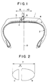
- Fig. 1 shows a widthwise cross section of a typical pneumatic tire according to this invention, in which reference numeral 1 indicates the pneumatic tire, 2 a radial carcass thereof, 3 a belt, 4 a belt reinforcing layer, 5 a tread, 6 a circumferential wide groove, 7 (see Fig. 2) tire grounding width (ground contact width), 8 the tire equatorial plane, 9 the inward direction of a vehicle on which the tire is mounted, and 10 the outward direction of a vehicle.
- reference numeral 1 indicates the pneumatic tire
- 2 a radial carcass thereof
- 3 a belt
- 4 a belt reinforcing layer
- 5 a tread
- 6 a circumferential wide groove
- 7 tire grounding width (ground contact width)
- 8 the tire equatorial plane
- 9 the inward direction of a vehicle on which the tire is mounted
- 10 the outward direction of a vehicle.
- Fig. 2 shows the tire grounding width 7 in more detail, wherein regions 11 corresponding to a tire grounding area are separated by a region 12 corresponding to the width of the circumferential wide groove 6.
- This pneumatic tire 1 has outside the radial carcass 2 comprising two plies the belt 3 comprising two rubber coated layers laminated with cross cord arrangement, that is with their cord crossing one another, one belt reinforcing layer 4 having substantially the same width as the belt 3 and comprising a rubber coated layer of organic fiber cords extending substantially in parallel with the circumference of the tire, and the tread 5 reinforced by the belt 3 and the belt reinforcing layer 4, and the tread is provided with one circumferential wide groove 6 extending along the tire circumference and having a sectional area of not less than 160 mm2.
- the circumferential wide groove 6 is arranged to be offset from the tire equatorial plane 8 in the widthwise direction by a distance L of 1/30 - 1/10 of the tire grounding width 7, and is preferably arranged to be offset in the inward direction 9 of a vehicle from the tire equatorial plane 8 when the tire is mounted on a vehicle.
- the tire grounding width 7 here is defined as the grounding width under the grounding condition of tire inflation pressure and tire load according to JIS, and a typical grounding print (ground contact print) with this tire grounding width 7 is shown in Fig. 2.
- the distance L between the tire equatorial plane 8 and the circumferential wide groove 6 is defined as the distance between the tire equatorial plane 8 and the widthwise center line of the circumferential wide groove 6 by measuring in the widthwise direction of the tire.
- the circumferential wide groove 6 has a width W of not less than 22 mm and not more than 3/10 of the tire grounding width 7, and a depth d of not less than 7 mm within the sectional area of not less than 160 mm2.
- width W of the circumferential groove is less than 22 mm and the depth is not less than 7 mm, block rigidity around the groove may not be sufficient, and when the width is more than 3/10 of the tire grounding width 7, steering may feel dull.
- the depth d of the circumferential wide groove 6 is less than 7 mm, sufficient drainage performance may not be obtained.
- the sectional shape of the circumferential wide groove can be selected from rectangular, triangular, round, trapezoidal and so on.
- the sectional width of the tire is preferably not less than 205 mm, and more preferably not less than 225 mm.
- the tread can be provided with at least one circumferential groove having smaller sectional area (of less than 100 mm2, for example 38 mm2) when necessary.
- the carcass 2, the belt 3 and the belt reinforcing layer 4 are of conventional sectional shape as shown in Fig. 1, but the carcass 2, the belt 3 and the belt reinforcing layer 4 can be made concave inward in the radial direction of the tire together with the tread 5 (as shown for example in Fig. 3).
- this shape is preferable when the tire cannot be provided with a sufficiently thick tread rubber where the circumferential wide groove is formed.
- the drawings do not show lateral grooves or sipes, these can be formed in this invention when necessary as in conventional tires.
- a circumferential groove arranged in a tread of a pneumatic tire contributes to drainage performance, but has the disadvantage that it generates air column resonance sound easily in the grounded circumferential groove and is a source of noise.
- This air column resonance sound is generated mainly by the following. That is, it is thought that a tube-like space is formed when the circumferential groove comes into contact with the road surface and the air in the space is compressed by grounding, and the difference of air pressure between the stepping-in side and the stepping-out side of the tire grounding surface occurs in said space, and sudden flow of the air in the space caused by this difference of air pressure generates the air column resonance sound.
- one way to restrain the air column resonance sound is to restrain the sudden flow of the air in said space outward by preventing the difference of the air pressure in said space from occurring.
- the inventors have studied the manner of arranging the circumferential groove which contributes to drainage performance and restraining the air column resonance sound which is the disadvantage of the circumferential groove as mentioned above.
- the sectional area of the circumferential groove was formed to be not less than 160 mm2, which was considerably larger than that of a conventional circumferential groove so that it might be difficult for the difference of air pressure to occur.
- the air column resonance sound was largely reduced, but there occurred a new problem that sufficient cornering force could not be obtained and cornering performance was degraded because the negative ratio was large and the grounding area of the tire was largely decreased.
- the cornering performance and drainage performance was enhanced and the noise was reduced.
- the optimized range of the position of the circumferential groove needed to be defined.
- the pneumatic tire 1 according to this invention is provided in the tread 5 with a circumferential wide groove 6 extending around the tire circumference and having a sectional area of not less than 160 mm2, and the circumferential wide groove 6 is arranged to be offset from the tire equatorial plane 8 in the widthwise direction of the tire by a distance L of 1/30 - 1/10 of the tire grounding width 7, and in particular the circumferential wide groove 6 is arranged to be offset in the inward direction 9 of a vehicle from the tire equatorial plane 8 viewing the tire mounted on the vehicle.
- the air column resonance sound can be restrained, the outer tread portion can retain sufficient grounding area, and the groove has a sufficient effect to drain water entering the tire grounding region rearward.
- a pneumatic tire used as example 1 has a sectional shape as shown in Fig. 1 and a tire size of 255/40R17, and has outside a radial carcass 2 comprising two rubber coated plies of rayon cords a belt 3 comprising two rubber coated layers laminated with cross cord arrangement each of which has a cord angle of 25° with respect to the tire equatorial plane, one belt reinforcing layer 4 having substantially the same width as the belt 3 and comprising a rubber coated layer of nylon cords extending substantially in parallel with the circumference of the tire, and the tread 5 reinforced by the belt 3 and the belt reinforcing layer 4, wherein the tread is provided with one circumferential wide groove 6 extending along the tire circumference and having a sectional area of 240 mm2 (width: 30 mm, depth: 8 mm, sectional shape: rectangle).
- a pneumatic tire used as example 2 has substantially the same structure as the example 1 except that the sectional area of the circumferential wide groove 6 is 160 mm2 (width: 20 mm, depth: 8 mm, sectional shape: rectangle).
- a pneumatic tire used as example 3 has a sectional shape as shown in Fig. 3 and a tire size of 225/50ZR16, and has outside a radial carcass 2 having an up-down structure of two rubber coated plies of rayon cords a belt 3 comprising two rubber coated layers laminated with cross cord arrangement each of which has a cord angle of 25° with respect to the tire equatorial plane, two belt reinforcing layers 4 each comprising a rubber coated layer of nylon cords wound spirally around the circumference of the tire across the whole belt width, and the tread 5 reinforced by the belt 3 and the belt reinforcing layers 4. Further this tire is provided with narrow layers 13 covering both edges of the belt for assisting high-speed running durability.
- the tread is provided with one circumferential wide groove 6 extending along the tire circumference and having a sectional area of 900 mm2 (width: 50 mm, depth: 18 mm, sectional shape: semicircular).
- a pneumatic tire used as example 4 has substantially the same structure as the example 3 except that the sectional area of the circumferential wide groove 6 is 200 mm2 (width: 25 mm, depth: 8 mm, sectional shape: semicircular).
- a pneumatic tire used as comparative example 1 has substantially the same structure as the tire of the example 1 except that a circumferential groove 6 having a sectional area of 150 mm2 is arranged on the equatorial plane.
- a pneumatic tire used as comparative example 2 has substantially the same structure as the tire of the example 1 except that a circumferential groove 6 having a sectional area of 200 mm2 is arranged on the equatorial plane.
- the noise test was evaluated by measuring sound pressure level at each running speed of a vehicle running at varied speeds when a microphone is set at certain distance from a vehicle and calculating the sound pressure at a speed of 50 km/h from these measured values. This evaluation is based on the tire noise test method according to JASO (Japanese Automobile Standard Organization) C606.
- the cornering performance test was evaluated by feeling by a skilled test-driver driving a vehicle with marking out of 10.
- Table 1 shows the test results.
- values of the noise are indicated by reduced sound pressure level on the basis of the sound pressure level of the comparative example 1 as a control. Also the larger is the value of the cornering performance, the better is the performance.
- Table 1 Comp. exmpl 1 Comp. exmpl 2 Exmpl 1 Exmpl 2 Exmpl 3 Exmpl 4 Noise (db) Control - 1.5 - 1.7 - 1.5 - 2.8 - 1.6 Cornering performance 6 4 7 6 6 7
- test results show that the tires of examples 1 - 4 have reduced noise and enhanced cornering performance in comparison with the tires of comparative examples 1 and 2.
- the pneumatic tires 1 of this invention in which one circumferential wide groove 6 extending along the tire circumference and having a sectional width of not less than 160 mm2 is arranged to be offset in the tire widthwise direction from the equatorial plane 8 by the distance of 1/30 - 1/10 of the tire grounding width 7, and in particular arranged to be offset in the inward direction 9 of a vehicle from the equatorial plane 8 viewing the tire mounted on a vehicle, the tire noise can be reduced because of restraining air column resonance sound.
- cornering performance can be retained because the grounding area of the inner tread portion producing large cornering force can be retained.
Landscapes
- Engineering & Computer Science (AREA)
- Mechanical Engineering (AREA)
- Tires In General (AREA)
Applications Claiming Priority (4)
| Application Number | Priority Date | Filing Date | Title |
|---|---|---|---|
| JP224447/93 | 1993-09-09 | ||
| JP22444793 | 1993-09-09 | ||
| JP125171/94 | 1994-06-07 | ||
| JP6125171A JPH07125508A (ja) | 1993-09-09 | 1994-06-07 | 空気入りタイヤ |
Publications (2)
| Publication Number | Publication Date |
|---|---|
| EP0646480A1 true EP0646480A1 (de) | 1995-04-05 |
| EP0646480B1 EP0646480B1 (de) | 1996-12-11 |
Family
ID=26461684
Family Applications (1)
| Application Number | Title | Priority Date | Filing Date |
|---|---|---|---|
| EP19940306127 Expired - Lifetime EP0646480B1 (de) | 1993-09-09 | 1994-08-19 | Luftreifen |
Country Status (4)
| Country | Link |
|---|---|
| EP (1) | EP0646480B1 (de) |
| JP (1) | JPH07125508A (de) |
| DE (1) | DE69401111T2 (de) |
| ES (1) | ES2098102T3 (de) |
Cited By (11)
| Publication number | Priority date | Publication date | Assignee | Title |
|---|---|---|---|---|
| EP0738616A1 (de) * | 1995-04-21 | 1996-10-23 | Semperit Reifen Aktiengesellschaft | Fahrzeugreifen |
| US6796350B1 (en) * | 1999-07-26 | 2004-09-28 | Dunlop Gmbh | Vehicle tire having non-uniformly profiled tread with respect to its center |
| US6918420B2 (en) * | 2000-12-19 | 2005-07-19 | Sumitomo Rubber Industries, Ltd. | Pneumatic tire including groove bottom rib |
| WO2006114327A1 (de) * | 2005-04-28 | 2006-11-02 | Felsen Hans-Juergen | Verfahren zur verminderung der geräuschemission bei einem fahrzeugreifen sowie hierfür geeigneter fahrzeugreifen |
| US20090242091A1 (en) * | 2004-02-03 | 2009-10-01 | The Goodyear Tire & Rubber Company | Tire with rubber tread of circumferential zones with graduated physical properties |
| US7731758B2 (en) | 1997-06-13 | 2010-06-08 | Aventis Pharmaceuticals Holdings, Inc. | Implant for subcutaneous or intradermal injection |
| CN102858558A (zh) * | 2010-04-30 | 2013-01-02 | 米其林企业总公司 | 用于拖车式重型车辆的轮胎胎面 |
| CN108367630A (zh) * | 2015-12-07 | 2018-08-03 | 株式会社普利司通 | 轮胎 |
| US11325424B2 (en) * | 2017-01-27 | 2022-05-10 | Compagnie Generale Des Etablissements Michelin | Tire with optimised tread |
| US20240408915A1 (en) * | 2021-12-10 | 2024-12-12 | Bridgestone Corporation | Pneumatic radial tire for passenger vehicles |
| US20250033418A1 (en) * | 2021-12-10 | 2025-01-30 | Bridgestone Corporation | Pneumatic radial tire for passenger vehicles |
Families Citing this family (5)
| Publication number | Priority date | Publication date | Assignee | Title |
|---|---|---|---|---|
| JPH11310010A (ja) * | 1998-04-28 | 1999-11-09 | Toyo Tire & Rubber Co Ltd | 空気入りラジアルタイヤ |
| DE19941339B4 (de) * | 1999-08-31 | 2016-06-09 | Goodyear Dunlop Tires Germany Gmbh | Fahrzeugreifen |
| JP4557343B2 (ja) * | 2000-01-25 | 2010-10-06 | 株式会社ブリヂストン | 空気入りラジアルタイヤ |
| JP2009101775A (ja) * | 2007-10-22 | 2009-05-14 | Bridgestone Corp | 空気入りタイヤ、及び空気入りタイヤの装着方法 |
| JP6088335B2 (ja) * | 2013-04-12 | 2017-03-01 | 株式会社ブリヂストン | 空気入りタイヤ |
Citations (4)
| Publication number | Priority date | Publication date | Assignee | Title |
|---|---|---|---|---|
| DE3624408A1 (de) * | 1986-07-18 | 1988-02-18 | Uniroyal Englebert Gmbh | Fahrzeugluftreifen |
| DE3916711A1 (de) * | 1989-05-23 | 1990-11-29 | Klaus D Dipl Ing Debus | Tiefrillen-reifen - aqua-planing-verhinderungs-reifen |
| EP0503404A1 (de) * | 1991-03-08 | 1992-09-16 | The Goodyear Tire & Rubber Company | Luftreifen mit verbesserter Nassgriffigkeit |
| EP0508090A1 (de) * | 1991-03-08 | 1992-10-14 | The Goodyear Tire & Rubber Company | Luftreifen mit besonderer Bodenberührungsfläche |
-
1994
- 1994-06-07 JP JP6125171A patent/JPH07125508A/ja active Pending
- 1994-08-19 DE DE1994601111 patent/DE69401111T2/de not_active Expired - Fee Related
- 1994-08-19 EP EP19940306127 patent/EP0646480B1/de not_active Expired - Lifetime
- 1994-08-19 ES ES94306127T patent/ES2098102T3/es not_active Expired - Lifetime
Patent Citations (4)
| Publication number | Priority date | Publication date | Assignee | Title |
|---|---|---|---|---|
| DE3624408A1 (de) * | 1986-07-18 | 1988-02-18 | Uniroyal Englebert Gmbh | Fahrzeugluftreifen |
| DE3916711A1 (de) * | 1989-05-23 | 1990-11-29 | Klaus D Dipl Ing Debus | Tiefrillen-reifen - aqua-planing-verhinderungs-reifen |
| EP0503404A1 (de) * | 1991-03-08 | 1992-09-16 | The Goodyear Tire & Rubber Company | Luftreifen mit verbesserter Nassgriffigkeit |
| EP0508090A1 (de) * | 1991-03-08 | 1992-10-14 | The Goodyear Tire & Rubber Company | Luftreifen mit besonderer Bodenberührungsfläche |
Cited By (14)
| Publication number | Priority date | Publication date | Assignee | Title |
|---|---|---|---|---|
| EP0738616A1 (de) * | 1995-04-21 | 1996-10-23 | Semperit Reifen Aktiengesellschaft | Fahrzeugreifen |
| US7731758B2 (en) | 1997-06-13 | 2010-06-08 | Aventis Pharmaceuticals Holdings, Inc. | Implant for subcutaneous or intradermal injection |
| US6796350B1 (en) * | 1999-07-26 | 2004-09-28 | Dunlop Gmbh | Vehicle tire having non-uniformly profiled tread with respect to its center |
| US6918420B2 (en) * | 2000-12-19 | 2005-07-19 | Sumitomo Rubber Industries, Ltd. | Pneumatic tire including groove bottom rib |
| US8662123B2 (en) * | 2004-02-03 | 2014-03-04 | The Goodyear Tire & Rubber Company | Tire with rubber tread of circumferential zones with graduated physical properties |
| US20090242091A1 (en) * | 2004-02-03 | 2009-10-01 | The Goodyear Tire & Rubber Company | Tire with rubber tread of circumferential zones with graduated physical properties |
| WO2006114327A1 (de) * | 2005-04-28 | 2006-11-02 | Felsen Hans-Juergen | Verfahren zur verminderung der geräuschemission bei einem fahrzeugreifen sowie hierfür geeigneter fahrzeugreifen |
| CN102858558A (zh) * | 2010-04-30 | 2013-01-02 | 米其林企业总公司 | 用于拖车式重型车辆的轮胎胎面 |
| US20130206292A1 (en) * | 2010-04-30 | 2013-08-15 | Michelin Recherche Et Technique S.A. | Tread for a tire for a trailer-type heavy vehicle |
| CN108367630A (zh) * | 2015-12-07 | 2018-08-03 | 株式会社普利司通 | 轮胎 |
| EP3388259A4 (de) * | 2015-12-07 | 2018-12-19 | Bridgestone Corporation | Reifen |
| US11325424B2 (en) * | 2017-01-27 | 2022-05-10 | Compagnie Generale Des Etablissements Michelin | Tire with optimised tread |
| US20240408915A1 (en) * | 2021-12-10 | 2024-12-12 | Bridgestone Corporation | Pneumatic radial tire for passenger vehicles |
| US20250033418A1 (en) * | 2021-12-10 | 2025-01-30 | Bridgestone Corporation | Pneumatic radial tire for passenger vehicles |
Also Published As
| Publication number | Publication date |
|---|---|
| DE69401111T2 (de) | 1997-05-15 |
| EP0646480B1 (de) | 1996-12-11 |
| DE69401111D1 (de) | 1997-01-23 |
| JPH07125508A (ja) | 1995-05-16 |
| ES2098102T3 (es) | 1997-04-16 |
Similar Documents
| Publication | Publication Date | Title |
|---|---|---|
| EP0646480B1 (de) | Luftreifen | |
| EP0688685B1 (de) | Luftreifen | |
| EP1288023B1 (de) | Geländegängiger Reifen | |
| US20040211501A1 (en) | Pneumatic tire | |
| JP6414245B2 (ja) | 空気入りタイヤ | |
| EP0798137A1 (de) | Radialer luftreifen | |
| EP0346106A1 (de) | Luftreifen | |
| KR101066806B1 (ko) | 공기 타이어 | |
| EP0870630B1 (de) | Luftreifen | |
| US11999195B2 (en) | Pneumatic tire | |
| EP1580030B1 (de) | Luftreifen | |
| EP0426068B1 (de) | Verfahren zum Montieren von Reifen | |
| JP3035005B2 (ja) | 空気入りラジアルタイヤのタイヤ対 | |
| EP0622253A1 (de) | Radiale Luftreifen | |
| US6164354A (en) | Pneumatic tire | |
| JP2769040B2 (ja) | 高速走行用空気入りラジアルタイヤ | |
| EP0321730B1 (de) | Radialer Luftreifen mit niedrigem Querschnittsprofil | |
| JP3332358B2 (ja) | 空気入りタイヤ | |
| JP2023010598A (ja) | タイヤ | |
| EP1182060B1 (de) | Luftreifen | |
| JP5217120B2 (ja) | 空気入りタイヤ | |
| JPH06191226A (ja) | 空気入りタイヤ | |
| JP3397450B2 (ja) | 空気入りタイヤ | |
| EP4722002A1 (de) | Luftreifen | |
| JP4363927B2 (ja) | 乗用車用ラジアルタイヤ |
Legal Events
| Date | Code | Title | Description |
|---|---|---|---|
| PUAI | Public reference made under article 153(3) epc to a published international application that has entered the european phase |
Free format text: ORIGINAL CODE: 0009012 |
|
| AK | Designated contracting states |
Kind code of ref document: A1 Designated state(s): DE ES FR GB IT |
|
| 17P | Request for examination filed |
Effective date: 19950605 |
|
| GRAG | Despatch of communication of intention to grant |
Free format text: ORIGINAL CODE: EPIDOS AGRA |
|
| 17Q | First examination report despatched |
Effective date: 19960417 |
|
| GRAH | Despatch of communication of intention to grant a patent |
Free format text: ORIGINAL CODE: EPIDOS IGRA |
|
| GRAH | Despatch of communication of intention to grant a patent |
Free format text: ORIGINAL CODE: EPIDOS IGRA |
|
| GRAA | (expected) grant |
Free format text: ORIGINAL CODE: 0009210 |
|
| AK | Designated contracting states |
Kind code of ref document: B1 Designated state(s): DE ES FR GB IT |
|
| ITF | It: translation for a ep patent filed | ||
| REF | Corresponds to: |
Ref document number: 69401111 Country of ref document: DE Date of ref document: 19970123 |
|
| ET | Fr: translation filed | ||
| REG | Reference to a national code |
Ref country code: ES Ref legal event code: FG2A Ref document number: 2098102 Country of ref document: ES Kind code of ref document: T3 |
|
| PGFP | Annual fee paid to national office [announced via postgrant information from national office to epo] |
Ref country code: FR Payment date: 19970811 Year of fee payment: 4 |
|
| PGFP | Annual fee paid to national office [announced via postgrant information from national office to epo] |
Ref country code: DE Payment date: 19970822 Year of fee payment: 4 |
|
| PGFP | Annual fee paid to national office [announced via postgrant information from national office to epo] |
Ref country code: ES Payment date: 19970828 Year of fee payment: 4 |
|
| PLBE | No opposition filed within time limit |
Free format text: ORIGINAL CODE: 0009261 |
|
| STAA | Information on the status of an ep patent application or granted ep patent |
Free format text: STATUS: NO OPPOSITION FILED WITHIN TIME LIMIT |
|
| 26N | No opposition filed | ||
| PG25 | Lapsed in a contracting state [announced via postgrant information from national office to epo] |
Ref country code: GB Free format text: LAPSE BECAUSE OF NON-PAYMENT OF DUE FEES Effective date: 19980819 |
|
| PG25 | Lapsed in a contracting state [announced via postgrant information from national office to epo] |
Ref country code: ES Free format text: LAPSE BECAUSE OF NON-PAYMENT OF DUE FEES Effective date: 19980820 |
|
| GBPC | Gb: european patent ceased through non-payment of renewal fee |
Effective date: 19980819 |
|
| PG25 | Lapsed in a contracting state [announced via postgrant information from national office to epo] |
Ref country code: FR Free format text: LAPSE BECAUSE OF NON-PAYMENT OF DUE FEES Effective date: 19990430 |
|
| PG25 | Lapsed in a contracting state [announced via postgrant information from national office to epo] |
Ref country code: DE Free format text: LAPSE BECAUSE OF NON-PAYMENT OF DUE FEES Effective date: 19990601 |
|
| REG | Reference to a national code |
Ref country code: FR Ref legal event code: ST |
|
| REG | Reference to a national code |
Ref country code: ES Ref legal event code: FD2A Effective date: 19990910 |
|
| PG25 | Lapsed in a contracting state [announced via postgrant information from national office to epo] |
Ref country code: IT Free format text: LAPSE BECAUSE OF NON-PAYMENT OF DUE FEES Effective date: 20050819 |