EP0647775A2 - Vorrichtung zur Leerlaufregelung einer Kraftfahrzeug-Brennkraftmaschine - Google Patents
Vorrichtung zur Leerlaufregelung einer Kraftfahrzeug-Brennkraftmaschine Download PDFInfo
- Publication number
- EP0647775A2 EP0647775A2 EP94113276A EP94113276A EP0647775A2 EP 0647775 A2 EP0647775 A2 EP 0647775A2 EP 94113276 A EP94113276 A EP 94113276A EP 94113276 A EP94113276 A EP 94113276A EP 0647775 A2 EP0647775 A2 EP 0647775A2
- Authority
- EP
- European Patent Office
- Prior art keywords
- internal combustion
- combustion engine
- exhaust gas
- cylinders
- catalytic converter
- Prior art date
- Legal status (The legal status is an assumption and is not a legal conclusion. Google has not performed a legal analysis and makes no representation as to the accuracy of the status listed.)
- Granted
Links
Images

Classifications
-
- F—MECHANICAL ENGINEERING; LIGHTING; HEATING; WEAPONS; BLASTING
- F02—COMBUSTION ENGINES; HOT-GAS OR COMBUSTION-PRODUCT ENGINE PLANTS
- F02D—CONTROLLING COMBUSTION ENGINES
- F02D41/00—Electrical control of supply of combustible mixture or its constituents
- F02D41/02—Circuit arrangements for generating control signals
- F02D41/14—Introducing closed-loop corrections
- F02D41/1438—Introducing closed-loop corrections using means for determining characteristics of the combustion gases; Sensors therefor
- F02D41/1439—Introducing closed-loop corrections using means for determining characteristics of the combustion gases; Sensors therefor characterised by the position of the sensor
- F02D41/1441—Plural sensors
- F02D41/1443—Plural sensors with one sensor per cylinder or group of cylinders
-
- F—MECHANICAL ENGINEERING; LIGHTING; HEATING; WEAPONS; BLASTING
- F02—COMBUSTION ENGINES; HOT-GAS OR COMBUSTION-PRODUCT ENGINE PLANTS
- F02D—CONTROLLING COMBUSTION ENGINES
- F02D41/00—Electrical control of supply of combustible mixture or its constituents
- F02D41/008—Controlling each cylinder individually
- F02D41/0087—Selective cylinder activation, i.e. partial cylinder operation
-
- F—MECHANICAL ENGINEERING; LIGHTING; HEATING; WEAPONS; BLASTING
- F02—COMBUSTION ENGINES; HOT-GAS OR COMBUSTION-PRODUCT ENGINE PLANTS
- F02D—CONTROLLING COMBUSTION ENGINES
- F02D41/00—Electrical control of supply of combustible mixture or its constituents
- F02D41/02—Circuit arrangements for generating control signals
- F02D41/021—Introducing corrections for particular conditions exterior to the engine
- F02D41/0235—Introducing corrections for particular conditions exterior to the engine in relation with the state of the exhaust gas treating apparatus
-
- F—MECHANICAL ENGINEERING; LIGHTING; HEATING; WEAPONS; BLASTING
- F01—MACHINES OR ENGINES IN GENERAL; ENGINE PLANTS IN GENERAL; STEAM ENGINES
- F01N—GAS-FLOW SILENCERS OR EXHAUST APPARATUS FOR MACHINES OR ENGINES IN GENERAL; GAS-FLOW SILENCERS OR EXHAUST APPARATUS FOR INTERNAL-COMBUSTION ENGINES
- F01N2430/00—Influencing exhaust purification, e.g. starting of catalytic reaction, filter regeneration, or the like, by controlling engine operating characteristics
- F01N2430/02—Influencing exhaust purification, e.g. starting of catalytic reaction, filter regeneration, or the like, by controlling engine operating characteristics by cutting out a part of engine cylinders
Definitions
- the invention relates to a device according to the preamble of patent claim 1 or 2.
- the internal combustion engine is operated in idle mode by firing all cylinders when the motor vehicle is stationary, this can lead to critical thermal behavior, in particular in the case of large-volume, multi-cylinder internal combustion engines, if the combustion generated amount of heat can not be dissipated by the coolant in the absence of wind.
- This object is achieved according to a first alternative of the invention in a device for idle control of a motor vehicle internal combustion engine with two rows of cylinders, each of which is assigned an exhaust gas catalytic converter with a lambda probe, in that the idle valves of one of the two rows of cylinders are alternately switched off when the internal combustion engine is idling and that the injection valve shutdown is switched from one row of cylinders to the other row of cylinders when the temperature of the exhaust gas catalytic converter assigned to the currently deactivated row of cylinders falls below a predetermined limit temperature.
- This first alternative of the invention is particularly suitable for 8- or 12-cylinder internal combustion engines with a V-shaped cylinder arrangement, which according to their firing order consist of two 4-cylinder or two 6-cylinder internal combustion engines. Particularly in the case of a 12-cylinder internal combustion engine constructed in this way, there is no appreciable deterioration in the idling quality because of the complete mass balance of a cylinder bank.
- the object on which the invention is based becomes in a device for idle control of a motor vehicle internal combustion engine solved with exhaust gas catalytic converter and lambda probe in that, when the internal combustion engine is idling, the injection valves are switched off sequentially depending on the internal combustion engine ignition sequence according to a predetermined program and that the sequential injection valve shutdown is canceled at least for a predetermined period of time when the temperature of the exhaust gas catalyst falls below a predetermined limit temperature.
- This embodiment of the invention is already suitable for 6-cylinder internal combustion engines.
- Each of the two alternatives of the invention ensures that the exhaust gas catalytic converter (s) cannot cool below the temperature required for proper exhaust gas conversion. This results in an improved exhaust gas emission behavior of the internal combustion engine. Furthermore, switching off individual cylinders when the internal combustion engine is idling can reduce their fuel consumption by approximately 35% when idling. Finally, the thermal behavior can be significantly improved by the invention, in particular in large-volume internal combustion engines in idle mode when the cooling effect of the airstream is missing.
- the sequential shutdown of the injection valves or the alternate shutdown of the injection valves of a cylinder bank in idle operation of the internal combustion engine only takes place when the coolant temperature of the internal combustion engine is greater than 80 ° C and / or the air temperature in the intake air collector is greater than 20 ° C is. This ensures that the single cylinder shutdown when the internal combustion engine is idling only when it is warmer Internal combustion engine and / or when the outside temperature is sufficiently warm.
- the sequential shutdown of the injectors or the alternate shutdown of the injectors of a row of cylinders only occurs at a vehicle speed greater than 5, so that no unpleasant torque jump occurs at the output of the internal combustion engine when parking or slow rolling of the motor vehicle by switching on the non-fired cylinders km / h canceled.
- the temperature of the or one of the exhaust gas catalysts is determined by measuring or monitoring the electrical voltage of the lambda probe assigned to the relevant exhaust gas catalyst.
- the logic diagram of FIG. 1 shows the functioning of a first exemplary embodiment of the invention.
- the device according to this first exemplary embodiment of the invention is suitable for idling control of a motor vehicle internal combustion engine with two rows of cylinders, each of which is associated with an exhaust gas catalytic converter with a lambda probe.
- the OR gate 1 receives as input variables the information as to whether the coolant temperature T K is greater than 80 ° C. and the further information as to whether the air temperature T S in the intake air manifold of the internal combustion engine is greater than 20 ° C. In the case of an internal combustion engine that is at operating temperature and not exactly extremely wintry ambient temperatures, the OR gate 1 then emits an enable signal to a first AND gate 2.
- this first AND gate 2 is supplied with the information as to whether the speed V FZG of the motor vehicle is less than 5 km / h. In the event that the speed V FZG of the motor vehicle is less than 5 km / h, the first AND gate 2 outputs a logic signal "1" to the second AND gate 3. When the open contact is closed, the second AND gate 3 receives a further logic signal "1" at its second input. This fulfills all the requirements that the injectors of one of the two rows of cylinders can be switched off when the internal combustion engine is idling. This result is stored in the memory element 4 until any change. The memory element 4 passes this information on to the two subsequent AND elements 5 and 6.
- the AND gate 5 receives the information about the voltage U L1 of the first lambda probe of the first exhaust gas catalytic converter at its second input
- the AND gate 6 receives the information about the voltage U L2 of the second lambda probe at its second input of the second catalytic converter.
- the first catalytic converter falls below a limit value U G , then this means that the cylinder row assigned to this first exhaust gas catalytic converter must be switched on again and thus the previously fired cylinder row which is assigned to the second exhaust gas catalytic converter can be switched off.
- the logic diagram of FIG. 2 is identical to the logic diagram of FIG. 1 in the first three logic elements 1, 2 and 3. Also in the embodiment of FIG. 2, the AND gate 3 emits a logical "1" signal to the AND gate 8 when the coolant temperature T K is greater than 80 ° C. and / or the air temperature T S in the air collector of the internal combustion engine is greater 20 ° C and in addition the vehicle speed V FZG is less than 5 km / h and finally the internal combustion engine is operated at idle, ie the idle contact is closed. At its second input, this AND gate 8 receives the information as to whether the electrical voltage U L of the lambda probe of the exhaust gas catalytic converter is greater or less than a limit voltage U G.
- the injectors can, depending on the engine ignition sequence, in an idle mode of the engine predetermined program can be switched off sequentially.
- the voltage of the lambda probe U L falls below the limit value U G , then this means that the exhaust gas catalytic converter has already cooled down to its minimum temperature required for the proper conversion, and consequently the sequential injection valve shutdown is canceled again at least for a predetermined period of time got to. Only when the catalytic converter has reached a sufficiently high operating temperature again, ie when the electrical voltage U L of the lambda probe is again greater than the limit voltage U G , can the injection valves be switched off sequentially again. The sequential shutdown of the injection valves of the internal combustion engine is then carried out by the internal combustion engine control unit 9.
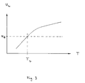
- the diagram of FIG. 3 shows the relationship between the electrical voltage U L of the lambda sensor as a function of the temperature T of the associated exhaust gas catalytic converter.
- the electrical voltage U L of the lambda probe decreases with decreasing temperature T of the exhaust gas catalytic converter.
- the limit temperature T G shown in the diagram of FIG. 3 represents the minimum temperature that the exhaust gas catalytic converter must have in order for it to function properly. In the diagram, this limit temperature T G corresponds to a limit voltage U G.
- the electrical voltage U L drops of the associated lambda Probe below the limit U G. Because of this relationship, the voltage U L of the lambda probe can be used as a measure of the temperature of the associated exhaust gas catalytic converter be so that a separate temperature sensor can be saved.
Landscapes
- Engineering & Computer Science (AREA)
- Chemical & Material Sciences (AREA)
- Combustion & Propulsion (AREA)
- Mechanical Engineering (AREA)
- General Engineering & Computer Science (AREA)
- Electrical Control Of Air Or Fuel Supplied To Internal-Combustion Engine (AREA)
- Exhaust Gas After Treatment (AREA)
- Output Control And Ontrol Of Special Type Engine (AREA)
Abstract
Description
- Die Erfindung betrifft eine Vorrichtung nach dem Oberbegriff des Patentanspruchs 1 oder 2.
- Es ist bereits bekannt, auch bei nur kurzfristigem Stillstand eines Kraftfahrzeuges dessen Brennkraftmaschine während der Stillstandsphase abzuschalten. Diese bekannte Vorrichtung wird häufig als "start-stop-automatik" bezeichnet. Bei dieser "start-stop-automatik" werden mit dem Abstellen der Brennkraftmaschine alle Zylinder abgeschaltet. Dies hat den Nachteil, daß der bzw. die Abgaskatalysatoren der Brennkraftmaschine sehr schnell auskühlen und folglich nach dem Brennkraftmaschinenstart wieder auf die erforderliche Konvertierungstemperatur durch entsprechendes Anfetten des Ansauggemisches gebracht werden müssen. Dies wirkt sich jedoch negativ auf die Abgasemissionen sowie auf den Kraftstoffverbrauch aus.
- Wenn dagegen die Brennkraftmaschine bei stehendem Kraftfahrzeug im Leerlauf durch Befeuerung aller Zylinder betrieben wird, kann dies insbesondere bei großvolumigen, vielzylindrigen Brennkraftmaschinen zu einem kritischen thermischen Verhalten führen, wenn die durch die Verbrennung erzeugte Wärmemenge bei fehlendem Fahrtwind durch das Kühlmittel nicht abgeführt werden kann.
- Es ist daher Aufgabe der Erfindung, eine Vorrichtung eingangs genannter Art anzugeben, durch die unter Beibehaltung der Abgasqualität der Kraftstoffverbrauch der Brennkraftmaschine im Leerlauf reduziert und als Folge davon das thermische Verhalten der Brennkraftmaschine verbessert wird.
- Diese Aufgabe wird gemäß einer ersten Alternative der Erfindung bei einer Vorrichtung zur Leerlaufsteuerung einer Kraftfahrzeug-Brennkraftmaschine mit zwei Zylinderreihen, denen jeweils ein Abgaskatalysator mit Lambda-Sonde zugeordnet ist, dadurch gelöst, daß im Leerlaufbetrieb der Brennkraftmaschine wechselweise die Einspritzventile einer der beiden Zylinderreihen abgeschaltet werden und daß eine Umschaltung der Einspritzventilabschaltung von einer Zylinderreihe auf die andere Zylinderreihe erfolgt, wenn die Temperatur des der gerade abgeschalteten Zylinderreihe zugeordneten Abgaskatalysators eine vorgegebene Grenztemperatur unterschreitet.
- Diese erste Alternative der Erfindung ist insbesondere für 8- bzw. 12-Zylinder-Brennkraftmaschinen mit V-förmiger Zylinderanordnung geeignet, welche gemäß ihrer Zündfolge aus zwei 4-Zylinder- bzw. aus zwei 6-Zylinder-Brennkraftmaschinen bestehen. Insbesondere bei einer derartig aufgebauten 12-Zylinder-Brennkraftmaschine ergibt sich wegen des vollkommenen Massenausgleichs einer Zylinderreihe keine nennenswerte Verschlechterung der Leerlaufqualität.
- Gemäß einer zweiten Alternative der Erfindung wird die der Erfindung zugrundeliegende Aufgabe bei einer Vorrichtung zur Leerlaufsteuerung einer KraftfahrzeugBrennkraftmaschine mit Abgaskatalysator und Lambda-Sonde dadurch gelöst, daß im Leerlaufbetrieb der Brennkraftmaschine die Einspritzventile abhängig von der Brennkraftmaschinenzündfolge nach einem vorgegebenen Programm sequentiell abgeschaltet werden und daS die sequentielle Einspritzventilabschaltung zumindest für eine vorgegebene Zeitspanne aufgehoben wird, wenn die Temperatur des Abgaskatalysators eine vorgegebene Grenztemperatur unterschreitet.
- Diese Ausgestaltung der Erfindung eignet sich auch bereits bei 6-Zylinder-Brennkraftmaschinen.
- Durch jede der beiden Alternativen der Erfindung wird erreicht, daS der bzw. die Abgaskatalysator(en) nicht unter die für eine ordnungsgemäße Abgaskonvertierung erforderliche Temperatur abkühlen können. Dies hat ein verbessertes Abgasemissionsverhalten der Brennkraftmaschine zur Folge. Ferner kann durch die Abschaltung einzelner Zylinder im Leerlaufbetrieb der Brennkraftmaschine deren Kraftstoffverbrauch im Leerlauf um ca. 35 % reduziert werden. Schließlich kann durch die Erfindung das thermische Verhalten insbesondere bei großvolumigen Brennkraftmaschinen im Leerlaufbetrieb, wenn die kühlende Wirkung des Fahrtwindes fehlt, deutlich verbessert werden.
- Gemäß einer vorteilhaften Weiterbildung der Erfindung erfolgt die sequentielle Abschaltung der Einspritzventile bzw. die wechselweise Abschaltung der Einspritzventile einer Zylinderreihe im Leerlaufbetrieb der Brennkraftmaschine nur dann, wenn die Kühlmitteltemperatur der Brennkraftmaschine größer als 80°C und/oder die Lufttemperatur im Ansaugluftsammler größer als 20°C ist. Damit wird erreicht, daS die Einzelzylinderabschaltung im Leerlaufbetrieb der Brennkraftmaschine nur bei betriebswarmer Brennkraftmaschine und/oder bei hinreichend warmer Außentemperatur erfolgt.
- Damit beim Einparken oder langsamen Dahinrollen des Kraftfahrzeuges durch Zuschalten der nichtbefeuerten Zylinder kein unangenehmer Drehmomentsprung am Ausgang der Brennkraftmaschine entsteht, wird gemäß einer weiteren Ausgestaltung der Erfindung die sequentielle Abschaltung der Einspritzventile bzw. die wechselweise Abschaltung der Einspritzventile einer Zylinderreihe erst bei einer Fahrzeuggeschwindigkeit größer als 5 km/h aufgehoben.
- Bei einer weiteren vorteilhaften Ausgestaltung der Erfindung wird die Temperatur des bzw. eines der Abgaskatalysatoren durch Messen oder Überwachen der elektrischen Spannung der dem betreffenden Abgaskatalysator zugeordneten Lambda-Sonde bestimmt.
- Im folgenden werden die beiden Alternativen der Erfindung jeweils anhand eines Ausführungsbeispiels erläutert.
- Es zeigen
- Fig. 1
- einen Logikplan, der die Schaltlogik der erfindungsgemäßen Zylinderreihenumschaltung wiedergibt,
- Fig. 2
- einen Logikplan, der die Schaltlogik für die sequentielle Einspritzabschaltung wiedergibt, und
- Fig. 3
- ein Diagramm, das die Temperaturabhängigkeit der elektrischen Spannung der Lambda-Sonde eines Abgaskatalysators wiedergibt.
- Der Logikplan von Fig. 1 gibt die Funktionsweise eines ersten Ausführungsbeispiels der Erfindung wieder. Die Vorrichtung gemäß dieses ersten Ausführungsbeispieles der Erfindung eignet sich zur Leerlaufsteuerung einer Kraftfahrzeug-Brennkraftmaschine mit zwei Zylinderreihen, denen jeweils ein Abgaskatalysator mit Lambda-Sonde zugeordnet ist. Bei diesem Ausführungsbeispiel erhält das ODER-Glied 1 als Eingangsgrößen die Information, ob die Kühlmitteltemperatur TK größer als 80°C ist sowie die weitere Information, ob die Lufttemperatur TS im Ansaugluftsammler der Brennkraftmaschine größer als 20°C ist. Bei einer betriebswarmen Brennkraftmaschine und nicht gerade extrem winterlichen Umgebungstemperaturen gibt dann das ODER-Glied 1 ein Freigabesignal an ein erstes UND-Glied 2 ab. Diesem ersten UND-Glied 2 wird als weitere Eingangsgröße die Information zugeführt, ob die Geschwindigkeit VFZG des Kraftfahrzeuges kleiner als 5 km/h ist. Für den Fall, daS die Geschwindigkeit VFZG des Kraftfahrzeuges kleiner als 5 km/h ist, gibt das erste UND-Glied 2 an das zweite UND-Glied 3 ein logisches Signal "1" ab. Bei geschlossenem Leerlaufkontakt erhält das zweite UND-Glied 3 an seinem zweiten Eingang ein weiteres logisches Signal "1". Damit sind alle Voraussetzungen erfüllt, daß im Leerlaufbetrieb der Brennkraftmaschine die Einspritzventile einer der beiden Zylinderreihen abgeschaltet werden können. Dieses Ergebnis ist bis zu einer etwaigen Änderung im Speicherglied 4 abgespeichert. Das Speicherglied 4 gibt diese Information an die beiden nachfolgenden UND-Glieder 5 und 6 weiter. Während das UND-Glied 5 an seinem zweiten Eingang die Information über die Spannung UL1 der ersten Lambda-Sonde des, ersten Abgaskatalysators erhält, erhält das UND-Glied 6 an seinem zweiten Eingang die Information über die Spannung UL2 der zweiten Lambda-Sonde des zweiten Abgaskatalysators. Für den Fall, daß die Spannung UL1 der ersten Lambda-Sonde des ersten Abgaskatalysators aufgrund der Abkühlung, des ersten Abgaskatalysators unter einen Grenzwert UG fällt, dann bedeutet dies, daß die diesem ersten Abgaskatalysator zugeordnete Zylinderreihe wieder zugeschaltet werden muß und damit die bisher befeuerte Zylinderreihe, die dem zweiten Abgaskatalysator zugeordnet ist, abgeschaltet werden kann. Wenn jedoch nach einer bestimmten Abschaltzeit der der nun abgeschalteten Zylinderreihe zugeordnete zweite Abgaskatalysator sich so stark abgekühlt hat, daß die Spannung UL2 der zweiten Lambda-Sonde des zweiten Abgaskatalysators einen Grenzwert UG unterschreitet, dann muß die dem zweiten Abgaskatalysator zugeordnete Zylinderreihe erneut befeuert werden, während die dem ersten Abgaskatalysator zugeordnete Zylinderreihe wieder abgeschaltet werden kann. Dieses wechselweise Abschalten der Einspritzventile einer der beiden Zylinderreihen im Leerlaufbetrieb der Brennkraftmaschine wird durch das schematisch dargestellte Brennkraftmaschinen-Steuergerät 7 vorgenommen.
- Der Logikplan von Fig. 2 stimmt mit dem Logikplan von Fig. 1 in den ersten drei logischen Gliedern 1, 2 und 3 identisch überein. Auch beim Ausführungsbeispiel von Fig. 2 gibt das UND-Glied 3 ein logisches "1"-Signal an das UND-Glied 8 ab, wenn die Kühlmitteltemperatur TK größer 80°C ist und/oder die Lufttemperatur TS im Luftsammler der Brennkraftmaschine größer 20°C ist und zusätzlich die Fahrzeuggeschwindigkeit VFZG kleiner als 5 km/h ist und schließlich die Brennkraftmaschine im Leerlauf betrieben wird, d. h. der Leerlaufkontakt geschlossen ist. Dieses UND-Glied 8 erhält an seinem zweiten Eingang die Information, ob die elektrische Spannung UL der Lambda-Sonde des Abgaskatalysators größer oder kleiner als eine Grenzspannung UG ist. Solange die Spannung UL der Lambda-Sonde größer als die Grenzspannung UG ist, können im Leerlaufbetrieb der Brennkraftmaschine die Einspritzventile abhängig von der Brennkraftmaschinenzündfolge nach einem vorgegebenen Programm sequentiell abgeschaltet werden. Wenn jedoch die Spannung der Lambda-Sonde UL unter den Grenzwert UG fällt, dann bedeutet dies, daß der Abgaskatalysator schon bis auf seine für die ordnungsgemäße Konvertierung minimal erforderliche Grenztemperatur abgekühlt ist und folglich die sequentielle Einspritzventilabschaltung zumindest für eine vorgegebene Zeitspanne wieder aufgehoben werden muß. Erst wenn der Abgaskatalysator wieder eine ausreichend hohe Betriebstemperatur erreicht hat, d. h., wenn die elektrische Spannung UL der Lambda-Sonde wieder größer als die Grenzspannung UG ist, dann können die Einspritzventile erneut sequentiell abgeschaltet werden. Die sequentielle Abschaltung der Einspritzventile der Brennkraftmaschine erfolgt dann durch das Brennkraftmaschinen-Steuergerät 9.
- In dem Diagramm von Fig. 3 ist der Zusammenhang der elektrischen Spannung UL der Lambda-Sonde in Abhängigkeit von der Temperatur T des zugehörigen Abgaskatalysators dargestellt. Wie dem Diagramm von Fig. 3 zu entnehmen ist, nimmt die elektrische Spannung UL der Lambda-Sonde mit abnehmender Temperatur T des Abgaskatalysators ab. Die im Diagramm von Fig. 3 eingezeichnete Grenztemperatur TG stellt die Mindesttemperatur dar, die der Abgaskatalysator für eine ordnungsgemäße Funktion haben muß. Dieser Grenztemperatur TG entspricht im Diagramm eine Grenzspannung UG. Wenn nun aufgrund einer abgeschalteten Zylinderreihe der zugehörige Abgaskatalysator unter die Betriebstemperatur TG abkühlt bzw. wenn der einzige Abgaskatalysator der Brennkraftmaschine aufgrund einer zu lange andauernden sequentiellen Abschaltung der Einspritzventile unter die Betriebstemperatur TG abkühlt, dann sinkt die elektrische Spannung UL der zugehörigen Lambda-Sonde unter den Grenzwert UG. Aufgrund dieses Zusammenhangs kann die Spannung UL der Lambda-Sonde als Maß für die Temperatur des zugehörigen Abgaskatalysators verwendet werden, so daß ein separater Temperaturfühler eingespart werden kann.
- Durch die erfindungsgemäße Abschaltung einzelner Einspritzventile im Leerlaufbetrieb der Brennkraftmaschine wird unter Beibehaltung der Abgasqualität eine Verminderung des Kraftstoffverbrauchs sowie eine Verbesserung des thermischen Verhaltens der Brennkraftmaschine erreicht.
Claims (5)
- Vorrichtung zur Leerlaufsteuerung einer Kraftfahrzeug-Brennkraftmaschine mit zwei Zylinderreihen, denen jeweils ein Abgaskatalysator mit Lambda-Sonde zugeordnet ist,
dadurch gekennzeichnet, daß im Leerlaufbetrieb der Brennkraftmaschine wechselweise die Einspritzventile einer der beiden Zylinderreihen abgeschaltet werden und daß eine Umschaltung der Einspritzventilabschaltung von einer Zylinderreihe auf die andere Zylinderreihe erfolgt, wenn die Temperatur (T) des der gerade abgeschalteten Zylinderreihe zugeordneten Abgaskatalysators eine vorgegebene Grenztemperatur (TG) unterschreitet. - Vorrichtung zur Leerlaufsteuerung einer Kraftfahrzeug-Brennkraftmaschine mit Abgaskatalysator und Lambda-Sonde,
dadurch gekennzeichnet, daß im Leerlaufbetrieb der Brennkraftmaschine die Einspritzventile abhängig von der Brennkraftmaschinenzündfolge nach einem vorgegebenen Programm sequentiell abgeschaltet werden und daß die sequentielle Einspritzventilabschaltung zumindest für eine vorgegebene Zeitspanne aufgehoben wird, wenn die Temperatur (T) des Abgaskatalysators eine vorgegebene Grenztemperatur (TG) unterschreitet. - Vorrichtung nach Anspruch 1 oder 2,
dadurch gekennzeichnet, daß die sequentielle Abschaltung der Einspritzventile bzw. die wechselweise Abschaltung der Einspritzventile einer Zylinderreihe im Leerlaufbetrieb der Brennkraftmaschine nur dann erfolgt, wenn die Kühlmitteltemperatur (TK) der Brennkraftmaschine größer als 80°C und/oder die Lufttemperatur (TS) im Ansaugluftsammler größer als 20°C ist. - Vorrichtung nach einem der vorhergehenden Ansprüche,
dadurch gekennzeichnet, daß die sequentielle Abschaltung der Einspritzventile bzw. die wechselweise Abschaltung der Einspritzventile einer Zylinderreihe erst bei einer Fahrzeuggeschwindigkeit (FFZG) größer als 5 km/h aufgehoben wird. - Vorrichtung nach einem der vorhergehenden Ansprüche,
dadurch gekennzeichnet, daß die Temperatur (T) des bzw. eines der Abgaskatalysatoren durch Messen oder Überwachen der elektrischen Spannung (UL) der dem betreffenden Abgaskatalysator zugeordneten Lambda-Sonde bestimmt wird.
Applications Claiming Priority (2)
| Application Number | Priority Date | Filing Date | Title |
|---|---|---|---|
| DE4334557 | 1993-10-11 | ||
| DE4334557A DE4334557A1 (de) | 1993-10-11 | 1993-10-11 | Vorrichtung zur Leerlaufregelung einer Kraftfahrzeug-Brennkraftmaschine |
Publications (3)
| Publication Number | Publication Date |
|---|---|
| EP0647775A2 true EP0647775A2 (de) | 1995-04-12 |
| EP0647775A3 EP0647775A3 (de) | 1996-07-17 |
| EP0647775B1 EP0647775B1 (de) | 2003-04-09 |
Family
ID=6499846
Family Applications (1)
| Application Number | Title | Priority Date | Filing Date |
|---|---|---|---|
| EP94113276A Expired - Lifetime EP0647775B1 (de) | 1993-10-11 | 1994-08-25 | Vorrichtung zur Leerlaufregelung einer Kraftfahrzeug-Brennkraftmaschine |
Country Status (3)
| Country | Link |
|---|---|
| US (1) | US5586432A (de) |
| EP (1) | EP0647775B1 (de) |
| DE (2) | DE4334557A1 (de) |
Cited By (1)
| Publication number | Priority date | Publication date | Assignee | Title |
|---|---|---|---|---|
| US6273840B1 (en) | 1999-02-24 | 2001-08-14 | Bayerische Motoren Werke Aktiengesellschaft | Method for shutting down and switching on motor vehicle internal-combustion engine cylinders |
Families Citing this family (15)
| Publication number | Priority date | Publication date | Assignee | Title |
|---|---|---|---|---|
| DE4423344A1 (de) * | 1994-07-04 | 1996-01-11 | Bayerische Motoren Werke Ag | Verfahren zur Erkennung von seitenverkehrt angeschlossenen Lambda-Sonden |
| DE19503317A1 (de) | 1995-02-02 | 1996-08-08 | Bayerische Motoren Werke Ag | Vorrichtung zur Abschaltsteuerung eines Einspritzventils bei Brennkraftmaschinen |
| US5801499A (en) * | 1995-07-11 | 1998-09-01 | Aisin Aw Co., Ltd. | Control system for a vehicular drive unit |
| JP3622279B2 (ja) * | 1995-07-31 | 2005-02-23 | 日産自動車株式会社 | 内燃機関の燃料供給制御装置 |
| JP3252793B2 (ja) * | 1998-05-15 | 2002-02-04 | トヨタ自動車株式会社 | 内燃機関の排気浄化装置 |
| FR2780100B1 (fr) * | 1998-06-17 | 2001-01-26 | Peugeot | Procede pour accroitre rapidement la temperature dans un pot catalytique au demarrage d'un moteur a combustion interne pour vehicule automobile |
| EP1126148B1 (de) * | 2000-01-05 | 2003-07-02 | Robert Bosch Gmbh | Verfahren zur Regelung der Wärmeverluste eines katalytischen Konverters während Schubbetrieb |
| DE10003903B4 (de) | 2000-01-29 | 2009-12-17 | Volkswagen Ag | Vorrichtung und Verfahren zur Steuerung eines Betriebes eines Mehrzylindermotors für Kraftfahrzeuge mit einer mehrflutigen Abgasreinigungsanlage |
| DE10161850B4 (de) * | 2001-12-15 | 2010-03-04 | Daimler Ag | Verfahren zum Betrieb einer Brennkraftmaschine eines Kraftfahrzeuges |
| JP3963105B2 (ja) * | 2002-01-18 | 2007-08-22 | 日産自動車株式会社 | 内燃機関の制御装置 |
| JP4725653B2 (ja) * | 2009-01-30 | 2011-07-13 | トヨタ自動車株式会社 | 多気筒内燃機関の運転制御装置 |
| US8214095B2 (en) * | 2009-05-27 | 2012-07-03 | GM Global Technology Operations LLC | Method and apparatus for detecting engine firing in a hybrid powertrain system |
| US8689541B2 (en) | 2011-02-16 | 2014-04-08 | GM Global Technology Operations LLC | Valvetrain control method and apparatus for conserving combustion heat |
| KR20170024853A (ko) * | 2015-08-26 | 2017-03-08 | 현대자동차주식회사 | 엔진 제어 방법 및 엔진 제어 시스템 |
| JP2017155699A (ja) * | 2016-03-03 | 2017-09-07 | 株式会社クボタ | 多目的車両 |
Family Cites Families (18)
| Publication number | Priority date | Publication date | Assignee | Title |
|---|---|---|---|---|
| US2937490A (en) * | 1957-08-12 | 1960-05-24 | Oxy Catalyst Inc | Catalytic purification of exhaust gases |
| US3756205A (en) * | 1971-04-26 | 1973-09-04 | Gen Motors Corp | Method of and means for engine operation with cylinders selectively unfueled |
| GB1427637A (en) * | 1972-08-30 | 1976-03-10 | Bosch Gmbh Robert | Internal combustion engine having an exhaust reactor and a protective device for the reactor |
| US4103486A (en) * | 1974-04-15 | 1978-08-01 | Nissan Motor Company, Ltd. | Method of controlling temperature in thermal reactor for engine exhaust gas and ignition system for performing same |
| JPS549B2 (de) * | 1974-06-01 | 1979-01-05 | ||
| DE2627286A1 (de) * | 1976-06-18 | 1977-12-29 | Daimler Benz Ag | Vorrichtung zur regelung einer mehrzylindrigen, grossvolumigen brennkraftmaschine |
| JPS5334017A (en) * | 1976-09-13 | 1978-03-30 | Nissan Motor Co Ltd | Control equipment of number of cylinder to be supplied fuel |
| DE2912796A1 (de) * | 1979-03-30 | 1980-10-09 | Daimler Benz Ag | Abgassystem fuer vorzugsweise achtzylindrige brennkraftmaschinen |
| JPS6121537Y2 (de) * | 1980-02-01 | 1986-06-27 | ||
| JPS5784228A (en) * | 1980-11-14 | 1982-05-26 | Shigeo Onchi | Device for controlling driving power of automobile |
| JPS59105941A (ja) * | 1982-12-08 | 1984-06-19 | Nissan Motor Co Ltd | 自動車用電子式エンジン制御装置用燃料カツト装置 |
| JPS6088833A (ja) * | 1983-10-19 | 1985-05-18 | Isuzu Motors Ltd | 内燃機関の燃料供給制御装置 |
| SU1315627A1 (ru) * | 1985-04-18 | 1987-06-07 | Джезказганский Научно-Исследовательский И Проектный Институт Цветной Металлургии | Способ работы двигател внутреннего сгорани |
| DE3623040A1 (de) * | 1986-07-09 | 1988-01-14 | Bosch Gmbh Robert | Verfahren zur kraftstoffeinspritzung |
| JPS6355337A (ja) * | 1986-08-26 | 1988-03-09 | Daihatsu Motor Co Ltd | 車両の走行速度制御方法 |
| JPS63134831A (ja) * | 1986-11-25 | 1988-06-07 | Toyota Motor Corp | 車両用定速走行制御装置 |
| JPH03124907A (ja) * | 1989-10-09 | 1991-05-28 | Mitsubishi Motors Corp | 触媒活性状態判定装置付き排気ガス浄化システム |
| DE4228053A1 (de) * | 1991-09-30 | 1993-04-01 | Siemens Ag | Verfahren zur zylinderspezifischen kennliniensteuerung und -anpassung fuer die elektronische steuerung von mehrzylinder-brennkraftmaschinen |
-
1993
- 1993-10-11 DE DE4334557A patent/DE4334557A1/de not_active Withdrawn
-
1994
- 1994-08-25 DE DE59410268T patent/DE59410268D1/de not_active Expired - Lifetime
- 1994-08-25 EP EP94113276A patent/EP0647775B1/de not_active Expired - Lifetime
- 1994-10-11 US US08/320,317 patent/US5586432A/en not_active Expired - Lifetime
Cited By (1)
| Publication number | Priority date | Publication date | Assignee | Title |
|---|---|---|---|---|
| US6273840B1 (en) | 1999-02-24 | 2001-08-14 | Bayerische Motoren Werke Aktiengesellschaft | Method for shutting down and switching on motor vehicle internal-combustion engine cylinders |
Also Published As
| Publication number | Publication date |
|---|---|
| US5586432A (en) | 1996-12-24 |
| DE4334557A1 (de) | 1995-04-13 |
| EP0647775B1 (de) | 2003-04-09 |
| DE59410268D1 (de) | 2003-05-15 |
| EP0647775A3 (de) | 1996-07-17 |
Similar Documents
| Publication | Publication Date | Title |
|---|---|---|
| DE2845043C2 (de) | Regelsystem für Brennkraftmaschinen | |
| EP0647775A2 (de) | Vorrichtung zur Leerlaufregelung einer Kraftfahrzeug-Brennkraftmaschine | |
| EP0433632B1 (de) | Verfahren zum Steuern eines Ottomotors ohne Drosselklappe | |
| DE3823277C2 (de) | ||
| DE3201756C2 (de) | Verfahren zum Steuern einer Brennkraftmaschine mit Vorverdichter | |
| DE10001583C2 (de) | Verfahren und Einrichtung zur Funktionsüberwachung eines Gasströmungssteuerorgans, insbesondere einer Drallkappe, bei einer Brennkraftmaschine | |
| DE3219021C3 (de) | ||
| DE3024385A1 (de) | Kraftstoffversorgungsanlage fuer brennkraftmaschinen | |
| EP0051723A2 (de) | Verfahren zum Betrieb eines elektronischen Steuersystems einer Brennkraftmaschine | |
| EP1045970B1 (de) | Verfahren zum betreiben einer brennkraftmaschine | |
| EP0640761A2 (de) | Steuerbare Zündanlage | |
| DE3138102C2 (de) | Verfahren zur Steuerung der Zündverstellung bei einer Brennkraftmaschine | |
| DE3546053C2 (de) | ||
| EP1222385A1 (de) | Vorrichtung und verfahren zur zündung einer brennkraftmaschine | |
| DE4018800C2 (de) | Verfahren und Vorrichtung zur Steuerung des Zündzeitpunktes einer Mehrzylinder-Brennkraftmaschine | |
| DE4035957A1 (de) | Verfahren zur funktionsueberwachung von brennkraftmaschinen | |
| DE2929797A1 (de) | Steuer-schaltungsanordnung fuer brennkraftmaschine | |
| DE69705150T2 (de) | Verfahren zur Diagnose des Wirkungsgrades eines stromabwärts von einem Katalysator angeordneten Stochiometrischen Abgassensors | |
| DE19909658A1 (de) | Verfahren und Vorrichtung zum Betreiben einer Brennkraftmaschine mit Benzindirekteinspritzung | |
| DE19736522A1 (de) | Verfahren zur Steuerung der Abgasrückführung bei einer Brennkraftmaschine | |
| DE3830574A1 (de) | Apparat zur steuerung des luft/kraftstoff-verhaeltnisses fuer einen mehrzylindermotor | |
| DE3525393C2 (de) | ||
| DE10332258A1 (de) | Zündschaltung für einen Verbrennungsmotor | |
| DE4134304A1 (de) | Zylinderindividuelle mengenkorrektur | |
| DE19609922B4 (de) | Sekundärluftsystemdiagnoseverfahren |
Legal Events
| Date | Code | Title | Description |
|---|---|---|---|
| PUAI | Public reference made under article 153(3) epc to a published international application that has entered the european phase |
Free format text: ORIGINAL CODE: 0009012 |
|
| AK | Designated contracting states |
Kind code of ref document: A2 Designated state(s): DE FR GB IT |
|
| PUAL | Search report despatched |
Free format text: ORIGINAL CODE: 0009013 |
|
| AK | Designated contracting states |
Kind code of ref document: A3 Designated state(s): DE FR GB IT |
|
| 17P | Request for examination filed |
Effective date: 19961206 |
|
| 17Q | First examination report despatched |
Effective date: 19980219 |
|
| APAB | Appeal dossier modified |
Free format text: ORIGINAL CODE: EPIDOS NOAPE |
|
| APAB | Appeal dossier modified |
Free format text: ORIGINAL CODE: EPIDOS NOAPE |
|
| APAD | Appeal reference recorded |
Free format text: ORIGINAL CODE: EPIDOS REFNE |
|
| APAB | Appeal dossier modified |
Free format text: ORIGINAL CODE: EPIDOS NOAPE |
|
| APAB | Appeal dossier modified |
Free format text: ORIGINAL CODE: EPIDOS NOAPE |
|
| APAD | Appeal reference recorded |
Free format text: ORIGINAL CODE: EPIDOS REFNE |
|
| APCB | Communication from the board of appeal sent |
Free format text: ORIGINAL CODE: EPIDOS OBAPE |
|
| APCB | Communication from the board of appeal sent |
Free format text: ORIGINAL CODE: EPIDOS OBAPE |
|
| APAB | Appeal dossier modified |
Free format text: ORIGINAL CODE: EPIDOS NOAPE |
|
| GRAG | Despatch of communication of intention to grant |
Free format text: ORIGINAL CODE: EPIDOS AGRA |
|
| GRAH | Despatch of communication of intention to grant a patent |
Free format text: ORIGINAL CODE: EPIDOS IGRA |
|
| GRAH | Despatch of communication of intention to grant a patent |
Free format text: ORIGINAL CODE: EPIDOS IGRA |
|
| GRAA | (expected) grant |
Free format text: ORIGINAL CODE: 0009210 |
|
| AK | Designated contracting states |
Designated state(s): DE FR GB IT |
|
| REG | Reference to a national code |
Ref country code: GB Ref legal event code: FG4D Free format text: NOT ENGLISH |
|
| GBT | Gb: translation of ep patent filed (gb section 77(6)(a)/1977) |
Effective date: 20030409 |
|
| ET | Fr: translation filed | ||
| PLBE | No opposition filed within time limit |
Free format text: ORIGINAL CODE: 0009261 |
|
| STAA | Information on the status of an ep patent application or granted ep patent |
Free format text: STATUS: NO OPPOSITION FILED WITHIN TIME LIMIT |
|
| 26N | No opposition filed |
Effective date: 20040112 |
|
| APAH | Appeal reference modified |
Free format text: ORIGINAL CODE: EPIDOSCREFNO |
|
| PGFP | Annual fee paid to national office [announced via postgrant information from national office to epo] |
Ref country code: DE Payment date: 20130724 Year of fee payment: 20 |
|
| PGFP | Annual fee paid to national office [announced via postgrant information from national office to epo] |
Ref country code: GB Payment date: 20130829 Year of fee payment: 20 Ref country code: FR Payment date: 20130828 Year of fee payment: 20 |
|
| PGFP | Annual fee paid to national office [announced via postgrant information from national office to epo] |
Ref country code: IT Payment date: 20130827 Year of fee payment: 20 |
|
| REG | Reference to a national code |
Ref country code: DE Ref legal event code: R071 Ref document number: 59410268 Country of ref document: DE |
|
| REG | Reference to a national code |
Ref country code: GB Ref legal event code: PE20 Expiry date: 20140824 |
|
| PG25 | Lapsed in a contracting state [announced via postgrant information from national office to epo] |
Ref country code: DE Free format text: LAPSE BECAUSE OF EXPIRATION OF PROTECTION Effective date: 20140826 |
|
| PG25 | Lapsed in a contracting state [announced via postgrant information from national office to epo] |
Ref country code: GB Free format text: LAPSE BECAUSE OF EXPIRATION OF PROTECTION Effective date: 20140824 |