EP0648022A2 - Système audio-vidéo - Google Patents
Système audio-vidéo Download PDFInfo
- Publication number
- EP0648022A2 EP0648022A2 EP94307321A EP94307321A EP0648022A2 EP 0648022 A2 EP0648022 A2 EP 0648022A2 EP 94307321 A EP94307321 A EP 94307321A EP 94307321 A EP94307321 A EP 94307321A EP 0648022 A2 EP0648022 A2 EP 0648022A2
- Authority
- EP
- European Patent Office
- Prior art keywords
- bus
- audio
- visual system
- cable
- image source
- Prior art date
- Legal status (The legal status is an assumption and is not a legal conclusion. Google has not performed a legal analysis and makes no representation as to the accuracy of the status listed.)
- Withdrawn
Links
Images





Classifications
-
- H—ELECTRICITY
- H04—ELECTRIC COMMUNICATION TECHNIQUE
- H04N—PICTORIAL COMMUNICATION, e.g. TELEVISION
- H04N7/00—Television systems
- H04N7/10—Adaptations for transmission by electrical cable
-
- H—ELECTRICITY
- H04—ELECTRIC COMMUNICATION TECHNIQUE
- H04N—PICTORIAL COMMUNICATION, e.g. TELEVISION
- H04N5/00—Details of television systems
- H04N5/44—Receiver circuitry for the reception of television signals according to analogue transmission standards
-
- H—ELECTRICITY
- H04—ELECTRIC COMMUNICATION TECHNIQUE
- H04B—TRANSMISSION
- H04B1/00—Details of transmission systems, not covered by a single one of groups H04B3/00 - H04B13/00; Details of transmission systems not characterised by the medium used for transmission
- H04B1/06—Receivers
- H04B1/16—Circuits
- H04B1/20—Circuits for coupling gramophone pick-up, recorder output, or microphone to receiver
- H04B1/207—Circuits for coupling gramophone pick-up, recorder output, or microphone to receiver with an audio or audio/video bus for signal distribution
Definitions
- the present invention relates generally to a audio-visual system, and in particular to an audio-visual system including a bus for interconnection of various components thereof.
- AV audio-visual
- an AV centre 1 (such as a television monitor, or the like) is connected to a plurality of image sources 2a, 2b and 2c, which may, for example, include a video tape deck, a tuner, satellite decoder, etc.
- the AV centre 1 is connected individually to each of the image sources 2a, 2b, 2c respectively via signal cables 3 which generally include an video signal cable and audio signal cable (left and right audio cables may be provided for stereo audio).
- the AV centre 1 is connected in series to the image sources 2a-2c via bus cables 5 interconnected via connectors 4.
- the bus cables generally include a - balance cable, + balance cable and ground cable.
- each of the image sources are provided with two connectors 4 for allowing series connection of the components and that an first (i.e. input) side connector 4, as well as the connector 4 of the AV centre 1 are provided with end resistance means (terminators) 6.
- the end resistance means 6 of the image sources 2a-2c are designed so as to be disabled in the case wherein bus cables are connected to both input and output sides of the component (2a -2c), and the end resistance 6 of the AV centre 1 is disabled according to the presence of a bus cable (output) being connected thereto.
- the end resistance means 6 of the AV centre 1 as well as of the image sources 2a and 2b are inactive due to the presence of the bus cables 5, while the end resistance 6 of the image source 2c is active, since no bus cable 5 is connected to the output side thereof.
- a number of cables, connectors etc., necessary for system operation may be substantially reduced, thus lowering costs.
- an audio-visual system comprising: an audio-visual system control component including a plurality at least a connector, said connector including an input terminal group and an output terminal group; switching means provided between said input terminal group and said output terminal group and operable so as to close an audio-visual bus circuit of said audio-visual system according to non-attachment of a plug of an AV bus cable to said connector and to open said audio-visual bus circuit of said audio-visual system according to attachment of said cable; said AV bus cable including input side and output side plugs interconnected via a bus line, said input side one of said plugs being received by said connector of said control component and the other of said plugs being receivable by an appropriate connector provided on an image source component to be connected to said control component.
- an AV control centre 10 which may be a television set, video monitor, or the like, is connected to a plurality of image source components 11a, 11b, 11c via a first AV signal connector 12 and a second AV bus connector 13.
- the image source components 11a, 11b and 11c respectively include corresponding connectors, that is an AV signal connector 14 for output of an image signal input to the AV signal connector 13 of the AV control centre 10 via an AV signal cable 16, and an AV bus connector 15 for connection to the AV bus connector 13 of the AV control centre 10 via an AV bus cable.
- a 1:1 correspondence is established in cable connections between the AV control centre 10 and any of the image source components 11a, 11b and 11c. That is, each image source component 11 requires an AV bus cable 18 and an AV signal cable 16 between itself and the AV control centre 10.
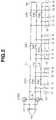
- the AV bus comprises a positive (+) balance line L1, a negative (-) balance line L2 and a ground line L3, the lines L1 and L2 are connected at first and second ends of the bus circuit by first and second resistors R1 and R2.
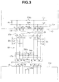
- the AV bus of the AV control centre 10 includes a plurality of switch groups t extracted from the AV bus lines L1, L2, L3 at each of the AV bus connectors 13 thereof.
- Each switch group includes an output terminal group t1 (t1, t1, t1) and an input terminal group t2 (t2, t2, t2) which comprise the terminal portions of each of the connectors 13.
- the input terminal group t1 and the output terminal group t2 as well as the AV bus lines L1, L2 and L3 are interconnected a switch group SW1.
- the switch group SW1 is operable to adopt a closed, or ON, state according to connection of a first plug 17a (Fig. 3) of the AV bus cable 18 to the connector 13 of the AV control centre 10 and to adopt an open, or OFF, state according to disconnection of a first plug 17a from one of the connectors 13.
- Fig. 13 shows a detailed circuit diagram of the interconnection between a connector 13 of the AV control centre 10, a first plug 17a, its AV bus cable 18 and a corresponding second plug 17b and the connector 15 of an image source component 11 to be connected to the AV system 1.
- the AV bus cable 18 comprises an output side bus line B0 and an input side bus line B1 each including a + balance line L1, a - balance line L2 and a ground line L3, similarly to the internal AV bus of the AV control centre 10.
- first ends of each of the bus lines B0 and B1 are connected to a switch group t3 of the first plug 17a, while second ends of the bus lines B0 and B1 are connected to a switch group t4 of a the second plug 17b of the AV bus cable 18.
- the second plug 17b further includes a switch group SW2 operable between the AV bus lines L1, L2, L3 of the output side bus line B0 and the AV bus lines (L1-L3) of the input side bus line B1 in a manner analogous to the switch group SW1 of the internal AV bus of the AV control centre 10. That is, the switch group SW2 is opened (switches assume an OFF, or open state) according to attachment of the second plug 17b to a connector 15 of an image source component 11 and closed (switches assume an ON, or closed state) according to disconnection of the second plug 17b from the connector 15.
- the connector 15 includes an input terminal group t5, an output terminal group t6, a detecting switch SW3, and a projecting member 21.
- the projecting member 21 is active to turn OFF the switch group SW2. Further, according to such connection, the detecting switch SW3 is closed (ON).
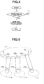
- OSD on-screen display
- the state of the switch group SW1 becomes OFF, while the state of the switch group SW2 of the AV bus cable 18 also becomes of OFF to produce the connective state of the AV system 1 as shown in Fig. 5.
- Fig. 6 shows a connective state of the AV system 1 if the third image source component 11c is disconnected from the system.
- the state of the switch group SW1 of the third connector 13 remains closed (ON) while the switch groups SW1 of the first and second connectors 13 are open (OFF) since they are connected to the image source components 11a and 11b.
- the resistor R2 of the internal AV bus of the AV control centre 10 is active to provide the end resistance for the overall AV bus of the AV system 1.
- a AV bus cable 18 is connected to the third connector 13 of the AV control centre 10 while in fact the second plug 17b of the AV bus cable 18 is not connected to the third image source component 11c, as shown in Fig. 7.
- the switch group SW1 of the third connector 13 of the AV control centre 10 will be caused to remain open.
- the switch group SW2 of the AV bus cable 18 will remain closed due to non-connection to the image source component 11c thus forming a loop back to the AV control centre 10, again allowing the resistor R2 of the internal AV bus of the AV control centre 10 to provide the end resistance for the overall AV bus of the AV system 1. Therefore, normal operation may be carried out and no malfunction will result.
- the second embodiment provides for the AV bus cable 18 and the AV signal cable 16 to be combined in a single unitary cable C.
- Connectors 22, 22, ... of the AV control centre 10 are suitable adapted to include terminals for the AV signal as are the connectors 23, 23, ... of the image source components 11a, 11b 11c, etc.
- the first and second plugs 24a and 24b of the unitary cable C are also adapted for transmission of the additional AV signal.
- the second embodiment is identical to the above-described embodiment.
- wiring is further simplified and overall neatness of the system when fully connected is enhanced.
- Fig. 9 shows a third embodiment of the AV system 1 of the invention.
- This embodiment basically comprises a modification of the connection between the image source components 11a, 11b, 11c and the AV bus cable 18.
- the AV bus cable 18 is permanently and non-releasably attached to the image source component 11.
- no switch group SW2 need be provided for loop back, since the AV bus cable 18 is integral to the image source component 11. According to this, cost and complexity may be further reduced with no compromise of functionality.
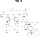
- Figs. 10-12 show a fourth embodiment of the AV system 1 according to the invention, the same reference numerals used in describing the first embodiment will again be utilized for simplicity of explanation.
- the third image source component 11c is utilized as a master component connected via and additional AV bus cable 18 to a slave component, that is, a fourth image source component 11d.
- the image source component 11 is provided with a connector 15 to be connected to the AV control centre 10 and a slave connector 15b for allowing connection of an additional image source component 11d.
- bus lines B2 and B3 are provided between the connectors 15 and 15a of the image source component. These bus lines B2 and B3 are interconnected by a switch group SW4 which is switched according to a projecting portion 19 of the first plug 17a of the AV bus cable 18, the AV signal may be connected via standard video in/out connectors and cables (i.e. AV cable 16) or may be integrated similarly to the second embodiment.
- Figs. 13-16 show a fifth embodiment of the AV system of the invention.
- a raised portion 27 is provided on a first plug 26a which connects to the AV control centre 10.
- An recessed portion 28 corresponds reciprocally to the arrangement of the raised portion, which has terminals t3, t3 ... arrange on side surfaces thereof.
- the projecting portion is provided on the raised portion 27 for enabling/disabling the switch group SW1, the AV bus cable 18 has a second plug 26b for connection to an image source component 11 as described above.
- the first plugs of a plurality of AV bus cables 18 may be stacked for deriving a plurality of AV bus connection via a single connector.
- the number of parts for the AV control centre 10 may be reduced and a plurality of connections may utilize a common ground line.
- a user may decide how many bus connections are required according to individual requirements and may add more as necessary. Thus convenience and simplicity are enhanced and basic costs may be reduced.
- the AV control centre 10 is connected to image source components 11a, 11b and 11c, the components 11 are not restricted only to image or video components but may also apply to cable or satellite audio signals, or other types of input.
Landscapes
- Engineering & Computer Science (AREA)
- Multimedia (AREA)
- Signal Processing (AREA)
- Computer Networks & Wireless Communication (AREA)
- Two-Way Televisions, Distribution Of Moving Picture Or The Like (AREA)
- Small-Scale Networks (AREA)
- Selective Calling Equipment (AREA)
- Details Of Connecting Devices For Male And Female Coupling (AREA)
- Stereophonic System (AREA)
- Circuit For Audible Band Transducer (AREA)
Applications Claiming Priority (3)
| Application Number | Priority Date | Filing Date | Title |
|---|---|---|---|
| JP5252679A JPH07107565A (ja) | 1993-10-08 | 1993-10-08 | Avシステム |
| JP252679/93 | 1993-10-08 | ||
| JP25267993 | 1993-10-08 |
Publications (2)
| Publication Number | Publication Date |
|---|---|
| EP0648022A2 true EP0648022A2 (fr) | 1995-04-12 |
| EP0648022A3 EP0648022A3 (fr) | 1999-10-20 |
Family
ID=17240737
Family Applications (1)
| Application Number | Title | Priority Date | Filing Date |
|---|---|---|---|
| EP94307321A Withdrawn EP0648022A3 (fr) | 1993-10-08 | 1994-10-05 | Système audio-vidéo |
Country Status (7)
| Country | Link |
|---|---|
| US (1) | US5486877A (fr) |
| EP (1) | EP0648022A3 (fr) |
| JP (1) | JPH07107565A (fr) |
| KR (1) | KR950013204A (fr) |
| CN (1) | CN1047900C (fr) |
| MY (1) | MY131564A (fr) |
| TW (1) | TW347949U (fr) |
Families Citing this family (13)
| Publication number | Priority date | Publication date | Assignee | Title |
|---|---|---|---|---|
| KR0170650B1 (en) * | 1993-11-27 | 1999-03-20 | Samsung Electronics Co Ltd | Audio and video signal input/output apparatus for a tv |
| US5786850A (en) * | 1994-02-17 | 1998-07-28 | Ultrak, Inc. | Multiple room portable camera system |
| WO1996031067A1 (fr) * | 1995-03-24 | 1996-10-03 | Ppt Vision, Inc. | Liaison video serie numerique a grande vitesse |
| DE19643734A1 (de) | 1996-10-23 | 1998-04-30 | Philips Patentverwaltung | Anordnung zur Fernseh-Außenübertragung einer Veranstaltung o. dgl. |
| KR100269878B1 (ko) * | 1997-08-22 | 2000-12-01 | 윤종용 | 반도체소자의금속배선형성방법 |
| US5950111A (en) * | 1997-09-25 | 1999-09-07 | Lucent Technologies Inc. | Self-terminating coaxial to unshielded twisted-pair cable passive CATV distribution panel |
| DE10145708B4 (de) * | 2000-09-19 | 2007-02-01 | Samsung Electronics Co., Ltd., Suwon | Vorrichtung und Verfahren zum Verbinden eines Basismoduls mit einem Funktionserweiterungsmodul in einem AV-System |
| KR100744184B1 (ko) * | 2001-05-09 | 2007-08-01 | 삼성전자주식회사 | 디스플레이장치 및 그 제어방법 |
| KR100455382B1 (ko) * | 2002-03-12 | 2004-11-06 | 삼성전자주식회사 | 듀얼 다마신 구조를 가지는 반도체 소자의 금속 배선 형성방법 |
| KR100484153B1 (ko) * | 2002-08-19 | 2005-04-19 | 삼성전자주식회사 | Av 장치용 배선 시스템 및 그를 채용한 av 시스템 |
| KR100561400B1 (ko) * | 2003-07-21 | 2006-03-16 | 삼성전자주식회사 | 외부 기기 연결시 사용자 안내 온 스크린 표시 방법 및그를 적용한 디스플레이 장치 |
| US9460684B2 (en) | 2008-01-31 | 2016-10-04 | Hewlett-Packard Development Company, L.P. | System and method for illuminating connector ports |
| US10484732B2 (en) * | 2015-12-29 | 2019-11-19 | Tv One Limited | Data processing backplane with serial bus communication loop |
Family Cites Families (5)
| Publication number | Priority date | Publication date | Assignee | Title |
|---|---|---|---|---|
| US4689683B1 (en) * | 1986-03-18 | 1996-02-27 | Edward Efron | Computerized studio for motion picture film and television production |
| DE3776379D1 (de) * | 1986-04-11 | 1992-03-12 | Siemens Ag | Einrichtung zum durchschalten von farbfernsehsignalen. |
| FR2610101B1 (fr) * | 1987-01-26 | 1989-05-12 | Aerospatiale | Procede et outillage pour l'alignement d'equipements a bord d'un vehicule porteur et particulierement a bord d'un aeronef |
| KR920001287B1 (ko) * | 1988-02-12 | 1992-02-10 | 니혼 호오소오 고오카이 | 디지탈 영상신호 처리장치 |
| JPH02260997A (ja) * | 1989-03-31 | 1990-10-23 | Toshiba Corp | 入出力切換回路 |
-
1993
- 1993-10-08 JP JP5252679A patent/JPH07107565A/ja active Pending
-
1994
- 1994-10-04 US US08/317,870 patent/US5486877A/en not_active Expired - Fee Related
- 1994-10-04 TW TW085211098U patent/TW347949U/zh unknown
- 1994-10-05 EP EP94307321A patent/EP0648022A3/fr not_active Withdrawn
- 1994-10-06 MY MYPI94002653A patent/MY131564A/en unknown
- 1994-10-07 KR KR1019940025661A patent/KR950013204A/ko not_active Withdrawn
- 1994-10-08 CN CN94118652A patent/CN1047900C/zh not_active Expired - Fee Related
Also Published As
| Publication number | Publication date |
|---|---|
| KR950013204A (ko) | 1995-05-17 |
| US5486877A (en) | 1996-01-23 |
| CN1112763A (zh) | 1995-11-29 |
| EP0648022A3 (fr) | 1999-10-20 |
| TW347949U (en) | 1998-12-11 |
| JPH07107565A (ja) | 1995-04-21 |
| MY131564A (en) | 2007-08-30 |
| CN1047900C (zh) | 1999-12-29 |
Similar Documents
| Publication | Publication Date | Title |
|---|---|---|
| US5486877A (en) | Audio visual system with automatic closing of a bus circuit when an AV unit is disconnected | |
| US9800930B2 (en) | Image processing apparatus and method for selective power supply | |
| US6393607B1 (en) | AC port device for cable television tap | |
| EP0588423A2 (fr) | Bus de commande pour système électronique grand public comportant plusieurs composants | |
| US20070298656A1 (en) | Switch apparatus for multiple high definition multimedia interface sources | |
| KR100263951B1 (ko) | 상호 연결 시스템용 장치 | |
| KR100264094B1 (ko) | 신호처리 시스템과 이 시스템에 사용하기 위한 장치 | |
| JPH0651881A (ja) | 通信ユニット | |
| GB2254512A (en) | Selectively interconnecting units in audio-visual systems | |
| US8181043B1 (en) | Methods and apparatus for improved remotely switchable power supply | |
| US6880036B2 (en) | Apparatus for receiving audiovisual programs | |
| US5396512A (en) | Port transceiver for providing communication between a signal transmitting and receiving machine and a space switch | |
| JP3661427B2 (ja) | 信号切換装置 | |
| JPH05110962A (ja) | 自動入力切換回路 | |
| KR100223206B1 (ko) | 영상신호 처리장치의 출력신호 선택방법 및 그 장치 | |
| KR100716161B1 (ko) | 텔레비전의 범용 에이/브이 입력 장치 | |
| JP4183062B2 (ja) | ビデオ切換えシステム | |
| JP2506929B2 (ja) | S−vhs映像入力切り換え回路 | |
| KR200256711Y1 (ko) | Av기기의 연결 상태 표시장치 | |
| JPH0316445A (ja) | 終端方式 | |
| KR200415693Y1 (ko) | 차량용 다수의 멀티미디어 기기의 영상표시를 위한인터페이스 시스템 | |
| KR950015046B1 (ko) | 에이브이(a/v) 기기의 입출력 자동 절환회로 | |
| WO2006128059A2 (fr) | Rallonge pour interface electrique avec fonction d'isolation | |
| JP5349158B2 (ja) | 入力信号切替え装置 | |
| KR101276836B1 (ko) | 영상기기 및 이를 이용한 입력신호 처리 방법 |
Legal Events
| Date | Code | Title | Description |
|---|---|---|---|
| PUAI | Public reference made under article 153(3) epc to a published international application that has entered the european phase |
Free format text: ORIGINAL CODE: 0009012 |
|
| AK | Designated contracting states |
Kind code of ref document: A2 Designated state(s): DE FR GB |
|
| PUAL | Search report despatched |
Free format text: ORIGINAL CODE: 0009013 |
|
| AK | Designated contracting states |
Kind code of ref document: A3 Designated state(s): DE FR GB |
|
| RIC1 | Information provided on ipc code assigned before grant |
Free format text: 6H 04B 1/20 A, 6H 04N 5/765 B |
|
| 17P | Request for examination filed |
Effective date: 20000414 |
|
| STAA | Information on the status of an ep patent application or granted ep patent |
Free format text: STATUS: THE APPLICATION HAS BEEN WITHDRAWN |
|
| 18W | Application withdrawn |
Withdrawal date: 20021008 |