EP0648977B1 - Bougie à incandescence - Google Patents
Bougie à incandescence Download PDFInfo
- Publication number
- EP0648977B1 EP0648977B1 EP94114747A EP94114747A EP0648977B1 EP 0648977 B1 EP0648977 B1 EP 0648977B1 EP 94114747 A EP94114747 A EP 94114747A EP 94114747 A EP94114747 A EP 94114747A EP 0648977 B1 EP0648977 B1 EP 0648977B1
- Authority
- EP
- European Patent Office
- Prior art keywords
- contact
- heating element
- hollow body
- glow plug
- ceramic
- Prior art date
- Legal status (The legal status is an assumption and is not a legal conclusion. Google has not performed a legal analysis and makes no representation as to the accuracy of the status listed.)
- Expired - Lifetime
Links
- 238000010438 heat treatment Methods 0.000 claims abstract description 46
- 239000000919 ceramic Substances 0.000 claims abstract description 38
- 239000004020 conductor Substances 0.000 claims abstract description 28
- 239000002184 metal Substances 0.000 claims description 4
- 238000007789 sealing Methods 0.000 claims description 3
- 239000007769 metal material Substances 0.000 claims description 2
- 239000012212 insulator Substances 0.000 abstract description 6
- 238000004519 manufacturing process Methods 0.000 description 5
- 238000013461 design Methods 0.000 description 4
- 238000000034 method Methods 0.000 description 2
- 238000012549 training Methods 0.000 description 2
- LFQSCWFLJHTTHZ-UHFFFAOYSA-N Ethanol Chemical compound CCO LFQSCWFLJHTTHZ-UHFFFAOYSA-N 0.000 description 1
- 229910003564 SiAlON Inorganic materials 0.000 description 1
- 239000000853 adhesive Substances 0.000 description 1
- 230000001070 adhesive effect Effects 0.000 description 1
- 238000011161 development Methods 0.000 description 1
- 230000018109 developmental process Effects 0.000 description 1
- 238000012545 processing Methods 0.000 description 1
- 238000005245 sintering Methods 0.000 description 1
- 229910000679 solder Inorganic materials 0.000 description 1
- 238000005476 soldering Methods 0.000 description 1
Images

Classifications
-
- F—MECHANICAL ENGINEERING; LIGHTING; HEATING; WEAPONS; BLASTING
- F23—COMBUSTION APPARATUS; COMBUSTION PROCESSES
- F23Q—IGNITION; EXTINGUISHING-DEVICES
- F23Q7/00—Incandescent ignition; Igniters using electrically-produced heat, e.g. lighters for cigarettes; Electrically-heated glowing plugs
- F23Q7/001—Glowing plugs for internal-combustion engines
Definitions
- the invention relates to a glow plug with a hollow body, in which a ceramic heating element with a sintered-in ceramic heating element is arranged, which protrudes axially on one side of the hollow body and whose heating element is connected to power supply connections and has a heating area.
- Such glow plugs with a ceramic conductor and a metal resistance coil as a heating element are known from DE 42 03 183 Al and DE 41 33 046 Al.
- Glow plugs are generally used as a starting aid in diesel engines and alcohol engines, for the ignition of additional heaters, for the ignition of gas burners, etc.
- the ceramic conductor consists of a U-shaped bent conductor piece which is arranged at the front end of the projecting part of the heating element and forms a first heating element.
- This first heating element is over a second heating element in the form of a coil made of a metallic material connected to the power supply connections.
- the heating coil is connected directly to the power supply connections.
- the object on which the invention is based is to design the glow plug of the type mentioned at the outset in such a way that it can be produced from fewer individual parts using a simple production process which comprises a smaller number of production steps and in which thermal overload at the contact points is avoided.
- contacts in particular solder contacts, are avoided in the heating area, so that no thermal overloads can occur at the contact points, the glow plug according to the invention being able to be produced using a simple method due to the configuration of the contacts in the form of contact surfaces on the heating element.
- the glow plug according to the invention has a heating element which is thermally and mechanically stable even at temperatures of over 1200 ° C.
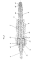
- the glow plug shown in Fig. 1 consists essentially of a metallic hollow body 1, in the cavity of which a ceramic heating element 2 is arranged, which protrudes axially at one end, ie at the motor-side end of the hollow body 1.
- the heating element 2 is essentially formed from a ceramic insulator 7, for example made of AlN, in which a ceramic conductor 6, for example made of SiC or SiAlON, z. B. is sintered.
- the ceramic conductor 6 is designed such that a zone 15 with a higher electrical resistance is formed in the motor-side heating rod tip, ie in the heating region 5.
- This zone 15 forms the actual heating resistor, which is preferably U-shaped in the manner shown in FIG. 1 is. This design can be achieved by appropriate doping of the ceramic conductor 6 in the zone 15 or by a reduction in cross section.
- Zone 15 is followed by a low-resistance region 14, which electrically connects the two ends of the heating resistor to the connection region, i.e. the power supply connections, which, in the embodiment shown in FIG. 1, are the metallic hollow body 1 as a ground connection and a screw or plug connection 3, which is likewise arranged in the hollow body 1 on the side opposite the heating region 5.
- the connection region i.e. the power supply connections, which, in the embodiment shown in FIG. 1, are the metallic hollow body 1 as a ground connection and a screw or plug connection 3, which is likewise arranged in the hollow body 1 on the side opposite the heating region 5.
- the ceramic conductor 6 is sintered into the ceramic insulator 7 by conventional manufacturing methods and provided with contact surfaces 8 and 9 for the ground contact and the plug contact by mechanical processing before or after the sintering process.
- the arrangement of the ceramic conductor 6 and the design of the contact surfaces 8 and 9 are such that the ceramic conductor 6 is electrically connected on the one hand in the region of its end section to the metallic hollow body 1 to form the ground contact and on the other hand to the plug connection 3 at the other end section.
- the ground contact surface 9 can also serve as a sealing seat.
- the contact surface 8 is connected to the connector 3, which can be designed, for example, as a circular connector.
- the contacting of the ceramic conductor 6 with the power supply connections, ie according to FIG. 1 with the metallic hollow body 1 and with the plug connection 3, is preferably a pressure contact.
- the heating element 2 is installed in the hollow body 1 in a pressure-tight manner via an insulating ring 4 over which the edge 12 of the hollow body 1 is flanged, the prestress achieved thereby resulting in a pressure on the contact surfaces 8 and 9.
- the prestress can also be achieved or increased by heating and axially compressing the hollow body 1 in the central region 13.
- the contacts can also be soldered or glued with a conductive adhesive or putty.
- contact parts in the form of metallic contact rings 10 and 11 are provided to improve the contacting on the contact surfaces 8 and 9, which are mechanically and electrically connected to the ceramic conductor 6 on the contact surfaces 8 and 9, for example by soldering, are connected.
- These contact rings 10 and 11 can be applied to the prefabricated heating element 2 or can be connected to the ceramic conductor 6 before the ceramic conductor with the contact rings 10, 11 is completely sintered into the ceramic insulator 7.
- a corresponding arrangement of the ceramic conductor 6 and the contact rings 10, 11 in the insulator 7 ensures that the ceramic conductor 6 is insulated against the hollow body 1 or the plug connection 3 on the points diametrically opposite the contacts.
- Fig. 2 shows an embodiment of the glow plug according to the invention, which differs from the embodiment shown in Fig. 1 in that it has a two-pole version compared to the single-pole version shown in Fig. 1.
- the contact surface 9 for the ground contact is formed on an outside of the ceramic conductor 6 in the low-resistance area within the metallic hollow body 1 2 and formed the ground contact there, this contact surface for the ground contact is also formed at the end of the ceramic conductor 6 in the exemplary embodiment shown in FIG. 2 and connected via a contact part 18 to the second pole 20 of the plug connection 3, the first pole of which in is designed in the same way as in the embodiment of FIG. 1.
- An insulating part 19 is provided between the two poles 3 and 20 of the connector 3.
- contact parts were designed as contact rings 10, 11 in the exemplary embodiment shown in FIG. 1, individual contact pieces 17, 18 are provided in the exemplary embodiment shown in FIG. 2, each arranged and designed for contact with the corresponding first or second pole are.
- the hollow body 1 is installed in an electrically insulated manner with respect to the heating elements, the surface 21 which is located at the point at which the ground contact surface 9 is formed in FIG. 1 as pure sealing surface serves.
- the glow plug shown in FIG. 2 corresponds to the structure already described in connection with FIG. 1.
- a special doping of the conductive ceramic of the ceramic conductor 6 can ensure that the ceramic conductor 6 has different resistance temperature coefficients in some areas, that is to say that an area with a positive resistance temperature coefficient is created, so that the glow plug is self-regulating.
- This self-regulating property can be provided over the entire area of the ceramic conductor 6 or only over a partial area be. This property is preferably present over the region 14.
Landscapes
- Engineering & Computer Science (AREA)
- Chemical & Material Sciences (AREA)
- Combustion & Propulsion (AREA)
- Mechanical Engineering (AREA)
- General Engineering & Computer Science (AREA)
- Resistance Heating (AREA)
- Investigating, Analyzing Materials By Fluorescence Or Luminescence (AREA)
- Spark Plugs (AREA)
Claims (8)
- Bougie à incandescence présentant un corps creux dans lequel est disposé un barreau céramique chauffant avec un élément céramique chauffant qui y est fritté, barreau qui dépasse axialement d'un côté du corps creux et dont l'élément chauffant est relié avec des bornes (1, 3) d'alimentation en courant et présente une zone chauffante (5), caractérisé par le fait que ce sont des parties de l'élément chauffant (6) elles-mêmes qui sont prévues comme surfaces de contact (8, 9) par l'intermédiaire desquelles l'élément chauffant (6) est en contact avec les bornes (1, 3) d'alimentation en courant, que les contacts de l'élément chauffant sont situés à l'extérieur de la zone chauffante (5) et que les contacts de l'élément chauffant sont obtenus sous contrainte de pression de ses surfaces de contact (8, 9) avec les bornes (1, 3) d'alimentation en courant.
- Bougie à incandescence selon la revendication 1, caractérisée par une bague d'isolation et d'étanchéité (4) qui est disposée, de l'autre côté, dans le corps creux (1) et au moyen de laquelle le bord (12) du corps creux (1) est serti de façon qu'apparaisse, selon la direction axiale, une précontrainte qui contraint en pression les surfaces de contact (8, 9).
- Bougie à incandescence selon la revendication 1, caractérisée par le fait qu'une précontrainte axiale qui met sous pression les surfaces de contact (8, 9) est produite par chauffage et rétreint axial du corps creux (1).
- Bougie à incandescence selon l'une des revendications précédentes, caractérisée par des pièces métalliques de contact (10, 11, 17, 18), qui sont prévues aux endroits de contact entre les surfaces de contact (8, 9) de l'élément chauffant (6) et les bornes d'alimentation en courant.
- Bougie à incandescence selon l'une des revendications précédentes, caractérisée par le fait que la surface de contact (8) pour la borne enfichable (3) est formée sur une portion d'extrémité du conducteur et que les surfaces de contact (9) pour la borne de masse sont formées en un endroit d'une zone de l'autre portion d'extrémité du conducteur qui se trouve dans le corps creux (1) constitué d'un matériau métallique, l'élément chauffant (6) étant disposé de façon telle, et la surface de contact (9) pour la borne de masse étant conçue de façon telle, qu'à cet endroit le contact de masse se fait avec le corps creux métallique (1).
- Bougie à incandescence selon l'une des revendications 1 à 5, caractérisée par le fait que le corps creux (1) est isolé par rapport à l'élément chauffant (6) et que la surface de contact pour la borne de masse est formée à l'autre extrémité de l'élément chauffant (6) et est reliée avec le pôle de masse (20) d'une fiche de borne bipolaire (3, 20).
- Bougie à incandescence selon l'une des revendications précédentes, caractérisée par le fait que l'élément chauffant (6) est un conducteur céramique.
- Bougie à incandescence selon la revendication 7, caractérisée par le fait que le conducteur céramique (6) est dopé, au moins partiellement, avec des différences de façon que se forment des zones à coefficient de température positif de la résistance et à coefficient de température négatif de la résistance.
Priority Applications (1)
| Application Number | Priority Date | Filing Date | Title |
|---|---|---|---|
| DE59402135.9T DE59402135C5 (de) | 1993-10-15 | 1994-09-19 | Glühkerze |
Applications Claiming Priority (2)
| Application Number | Priority Date | Filing Date | Title |
|---|---|---|---|
| DE4335292A DE4335292A1 (de) | 1993-10-15 | 1993-10-15 | Glühkerze |
| DE4335292 | 1993-10-15 |
Publications (4)
| Publication Number | Publication Date |
|---|---|
| EP0648977A2 EP0648977A2 (fr) | 1995-04-19 |
| EP0648977A3 EP0648977A3 (fr) | 1995-08-16 |
| EP0648977B1 true EP0648977B1 (fr) | 1997-03-19 |
| EP0648977B2 EP0648977B2 (fr) | 2001-11-21 |
Family
ID=6500295
Family Applications (1)
| Application Number | Title | Priority Date | Filing Date |
|---|---|---|---|
| EP94114747A Expired - Lifetime EP0648977B2 (fr) | 1993-10-15 | 1994-09-19 | Bougie à incandescence |
Country Status (6)
| Country | Link |
|---|---|
| US (1) | US5589091A (fr) |
| EP (1) | EP0648977B2 (fr) |
| JP (1) | JP3712134B2 (fr) |
| AT (1) | ATE150537T1 (fr) |
| DE (2) | DE4335292A1 (fr) |
| ES (1) | ES2101416T5 (fr) |
Families Citing this family (32)
| Publication number | Priority date | Publication date | Assignee | Title |
|---|---|---|---|---|
| DE19506950C2 (de) * | 1995-02-28 | 1998-07-23 | Bosch Gmbh Robert | Glühstiftkerze für Dieselmotoren |
| US5676100A (en) * | 1996-08-30 | 1997-10-14 | Caterpillar Inc. | Glow plug assembly |
| US5880432A (en) * | 1996-12-23 | 1999-03-09 | Le-Mark International Ltd. | Electric heating device with ceramic heater wedgingly received within a metalic body |
| US6144015A (en) * | 1998-09-25 | 2000-11-07 | General Motors Corporation | Glow sensor--ceramic flat plate |
| DE19914619A1 (de) * | 1999-03-31 | 2000-10-12 | Beru Ag | Verfahren zum abdichtenden Verschließen des anschlußseitigen Endbereichs des Glührohres einer Glühkerze und Glühkerzen mit verfahrensgemäßem Verschluß |
| US6184497B1 (en) * | 1999-06-16 | 2001-02-06 | Le-Mark International Ltd. | Multi-layer ceramic heater element and method of making same |
| US6084212A (en) * | 1999-06-16 | 2000-07-04 | Le-Mark International Ltd | Multi-layer ceramic heater element and method of making same |
| DE19930334C2 (de) * | 1999-07-02 | 2003-07-31 | Beru Ag | Keramischer Heizstab und diesen enthaltende Glühkerze und Verfahren zu dessen Herstellung |
| WO2001016529A1 (fr) * | 1999-08-27 | 2001-03-08 | Robert Bosch Gmbh | Bougie crayon de prechauffage en ceramique |
| HUP0202789A2 (en) * | 1999-08-27 | 2003-01-28 | Bosch Gmbh Robert | Ceramic sheathed element glow plug |
| US6285008B1 (en) * | 2000-01-11 | 2001-09-04 | Federal-Mogul World Wide, Inc. | Ignition plug and method of manufacture |
| DE10041282B4 (de) * | 2000-08-22 | 2005-02-10 | Beru Ag | Verfahren zur Verbindung eines Heizstabes einer Glühkerze mit ihrem Glühkerzenkörper und eine entsprechende Glühkerze |
| US6346688B1 (en) * | 2000-10-24 | 2002-02-12 | O'donnell Steven B. | Glow plug with crimp-secured washer and method |
| DE10053327C2 (de) * | 2000-10-27 | 2003-04-10 | Bosch Gmbh Robert | Stiftheizer |
| US6342690B1 (en) * | 2000-12-01 | 2002-01-29 | O'donnell Steven B. | Glow plug assembly method and construction |
| JP2002359060A (ja) * | 2001-05-31 | 2002-12-13 | Ngk Spark Plug Co Ltd | ヒータ、及びヒータの製造方法 |
| US6539905B1 (en) | 2001-10-25 | 2003-04-01 | International Engine Intellectual Property Company, L.L.C. | Glow plug connection apparatus |
| DE10228077A1 (de) * | 2002-06-20 | 2004-01-08 | Friedrich-Schiller-Universität Jena | Verfahren zur Herstellung einer mechanisch stabilen und elektrisch leitfähigen Verbindung zwischen einem metallischen Aufnahmeelement und einem vorzugsweise stiftförmigen keramischen Element, insbesondere bei Glühkerzen für Dieselmotoren |
| DE10339641A1 (de) * | 2003-08-28 | 2005-03-24 | Robert Bosch Gmbh | Glühstiftkerze mit besonders eingebettetem Kontaktelement |
| US7115836B2 (en) * | 2004-06-29 | 2006-10-03 | Ngk Spark Plug Co., Ltd. | Glow plug |
| DE102006016566B4 (de) * | 2005-09-22 | 2008-06-12 | Beru Ag | Zusammengesetzter Leiter, insbesondere für Glühkerzen für Dieselmotoren |
| JP5292317B2 (ja) * | 2008-02-20 | 2013-09-18 | 日本特殊陶業株式会社 | セラミックヒータ及びグロープラグ |
| DE102008035036B3 (de) * | 2008-07-26 | 2010-04-15 | Beru Ag | Keramische Glühkerze |
| WO2010060616A2 (fr) * | 2008-11-27 | 2010-06-03 | Borgwarner Beru Systems Gmbh | Bougie de préchauffage et son procédé de fabrication |
| KR101525634B1 (ko) * | 2009-03-30 | 2015-06-03 | 엔지케이 인슐레이터 엘티디 | 세라믹 히터 및 그 제조 방법 |
| JP5436687B2 (ja) * | 2010-09-27 | 2014-03-05 | 京セラ株式会社 | ヒータおよびこれを備えたグロープラグ |
| EP2626630B1 (fr) * | 2010-10-05 | 2019-06-26 | NGK Spark Plug Co., Ltd. | Procédé de production de bornes de bougie de préchauffage et procédé de production de bougies de préchauffage |
| DE102010062438A1 (de) * | 2010-12-06 | 2012-06-06 | Robert Bosch Gmbh | Glühkerze und Verfahren zu deren Herstellung |
| JP5973222B2 (ja) * | 2012-05-07 | 2016-08-23 | 日本特殊陶業株式会社 | グロープラグ及びその製造方法 |
| JP6088897B2 (ja) * | 2013-04-19 | 2017-03-01 | 日本特殊陶業株式会社 | グロープラグ |
| US9644532B2 (en) * | 2015-04-14 | 2017-05-09 | Sheldon J. Demmons | Autonomous glow driver for radio controlled engines |
| CN106912120A (zh) | 2015-08-21 | 2017-06-30 | 重庆利迈陶瓷技术有限公司 | 一种陶瓷电热体 |
Citations (1)
| Publication number | Priority date | Publication date | Assignee | Title |
|---|---|---|---|---|
| DE4133046A1 (de) * | 1990-10-04 | 1992-04-09 | Ngk Spark Plug Co | Selbst-regulierende gluehkerze |
Family Cites Families (14)
| Publication number | Priority date | Publication date | Assignee | Title |
|---|---|---|---|---|
| DE1213669B (de) * | 1964-01-14 | 1966-03-31 | Eiko Denki Corp | Gluehkerze mit einem elektrischen Widerstandsheizelement aus Siliziumkarbid |
| FR2398969A1 (fr) * | 1977-07-29 | 1979-02-23 | Eyquem | Bougie de chauffe pour demarrage de moteurs a allumage par compression |
| US4312120A (en) * | 1980-05-22 | 1982-01-26 | Bendix Autolite Corporation | Glow plug manufacture |
| DE3146653C2 (de) * | 1981-02-07 | 1986-09-04 | Robert Bosch Gmbh, 7000 Stuttgart | Glühkerze für Brennkraftmaschinen |
| US4418661A (en) * | 1981-02-07 | 1983-12-06 | Robert Bosch Gmbh | Glow plug, particularly for diesel engine |
| JPS5872821A (ja) * | 1981-10-26 | 1983-04-30 | Ngk Spark Plug Co Ltd | グロ−プラグとその製法 |
| US4582981A (en) * | 1983-06-23 | 1986-04-15 | Allied Corporation | Glow plug having a resistive surface film heater |
| EP0194535A3 (fr) * | 1985-03-15 | 1988-01-07 | Allied Corporation | Bougie à incandescence comprenant une résistance chauffante stratiforme d'une siliciure métallique |
| DE3701929A1 (de) * | 1986-01-22 | 1987-08-13 | Jidosha Kiki Co | Gluehkerze fuer eine dieselmaschine |
| JPS62148869U (fr) * | 1986-03-11 | 1987-09-19 | ||
| DE3802233A1 (de) * | 1987-01-22 | 1988-08-04 | Jidosha Kiki Co | Gluehkerze fuer einen dieselmotor |
| US5084607A (en) * | 1989-07-28 | 1992-01-28 | Caterpillar Inc. | Interference connection between a heating element and body of a glow plug |
| DE4014356A1 (de) * | 1990-05-04 | 1991-11-07 | Beru Werk Ruprecht Gmbh Co A | Gluehkerze |
| JP3044630B2 (ja) * | 1991-02-06 | 2000-05-22 | ボッシュ ブレーキ システム株式会社 | セラミックヒータ型グロープラグ |
-
1993
- 1993-10-15 DE DE4335292A patent/DE4335292A1/de not_active Ceased
-
1994
- 1994-09-19 AT AT94114747T patent/ATE150537T1/de not_active IP Right Cessation
- 1994-09-19 EP EP94114747A patent/EP0648977B2/fr not_active Expired - Lifetime
- 1994-09-19 DE DE59402135.9T patent/DE59402135C5/de not_active Expired - Lifetime
- 1994-09-19 ES ES94114747T patent/ES2101416T5/es not_active Expired - Lifetime
- 1994-10-11 JP JP24551394A patent/JP3712134B2/ja not_active Expired - Fee Related
- 1994-10-17 US US08/325,950 patent/US5589091A/en not_active Expired - Lifetime
Patent Citations (1)
| Publication number | Priority date | Publication date | Assignee | Title |
|---|---|---|---|---|
| DE4133046A1 (de) * | 1990-10-04 | 1992-04-09 | Ngk Spark Plug Co | Selbst-regulierende gluehkerze |
Also Published As
| Publication number | Publication date |
|---|---|
| ES2101416T5 (es) | 2002-02-16 |
| ES2101416T3 (es) | 1997-07-01 |
| JP3712134B2 (ja) | 2005-11-02 |
| US5589091A (en) | 1996-12-31 |
| EP0648977A3 (fr) | 1995-08-16 |
| ATE150537T1 (de) | 1997-04-15 |
| EP0648977B2 (fr) | 2001-11-21 |
| DE59402135D1 (de) | 1997-04-24 |
| JPH07217880A (ja) | 1995-08-18 |
| DE4335292A1 (de) | 1995-04-20 |
| EP0648977A2 (fr) | 1995-04-19 |
| DE59402135C5 (de) | 2014-07-24 |
Similar Documents
| Publication | Publication Date | Title |
|---|---|---|
| EP0648977B1 (fr) | Bougie à incandescence | |
| DE3342753C2 (fr) | ||
| DE69312235T2 (de) | Keramische Heizkörper für Glühkerze mit angepassten Wärmeausdehnungszahlen | |
| DE69710160T2 (de) | Keramische Glühkerze | |
| DE102006016566B4 (de) | Zusammengesetzter Leiter, insbesondere für Glühkerzen für Dieselmotoren | |
| DE3417170C2 (de) | Sauerstoffühler | |
| EP0907019A2 (fr) | Dispositif pour l'allumage d'un moteur à combustion interne | |
| DE3802233A1 (de) | Gluehkerze fuer einen dieselmotor | |
| DE19523977A1 (de) | Microchip-Sicherung | |
| EP0857281B1 (fr) | Bougie-crayon de prechauffage | |
| DE112005002980T5 (de) | Scheibenvaristor und Verfahren zu seiner Herstellung | |
| DE102007050634A1 (de) | Zündkerze | |
| DE19803594A1 (de) | Metallteil-Verbindungsstruktur, Metallteil-Verbindungsverfahren, keramische Heizvorrichtung und Herstellungsverfahren für keramische Heizvorrichtung | |
| WO2001042714A1 (fr) | Bougie de prechauffage | |
| EP1737071A2 (fr) | Connexion étanche à la pression d'un détonateur électronique | |
| EP2233353B1 (fr) | Allume-cigare, en particulier pour véhicules automobiles | |
| DD153720A5 (de) | Gluehkerze fuer verbrennungsmotoren | |
| DE10152886A1 (de) | Keramische Heizvorrichtung | |
| EP1267125B1 (fr) | Bougie à tige incandescente et procédé de fabrication | |
| DE19833316A1 (de) | Zündkerze für eine Brennkraftmaschine | |
| EP1295067B1 (fr) | Bougie crayon de prechauffage | |
| DE3430336A1 (de) | Simulations-kernreaktorbrennstab | |
| DE10339759B4 (de) | Zündkerze | |
| EP4238757B1 (fr) | Bilame plaqué | |
| CH357101A (de) | Lösbare Steckkontaktverbindungs-Einrichtung, enthaltend eine Kontaktfederanordnung und ein Kontaktmesser, bei der die Kontaktfederanordnung in einer Federleiste Aufnahme findet |
Legal Events
| Date | Code | Title | Description |
|---|---|---|---|
| PUAI | Public reference made under article 153(3) epc to a published international application that has entered the european phase |
Free format text: ORIGINAL CODE: 0009012 |
|
| AK | Designated contracting states |
Kind code of ref document: A2 Designated state(s): AT DE ES FR GB IT SE |
|
| PUAL | Search report despatched |
Free format text: ORIGINAL CODE: 0009013 |
|
| AK | Designated contracting states |
Kind code of ref document: A3 Designated state(s): AT DE ES FR GB IT SE |
|
| 17P | Request for examination filed |
Effective date: 19951109 |
|
| 17Q | First examination report despatched |
Effective date: 19960314 |
|
| GRAG | Despatch of communication of intention to grant |
Free format text: ORIGINAL CODE: EPIDOS AGRA |
|
| GRAH | Despatch of communication of intention to grant a patent |
Free format text: ORIGINAL CODE: EPIDOS IGRA |
|
| GRAH | Despatch of communication of intention to grant a patent |
Free format text: ORIGINAL CODE: EPIDOS IGRA |
|
| GRAA | (expected) grant |
Free format text: ORIGINAL CODE: 0009210 |
|
| AK | Designated contracting states |
Kind code of ref document: B1 Designated state(s): AT DE ES FR GB IT SE |
|
| REF | Corresponds to: |
Ref document number: 150537 Country of ref document: AT Date of ref document: 19970415 Kind code of ref document: T |
|
| ITF | It: translation for a ep patent filed | ||
| REF | Corresponds to: |
Ref document number: 59402135 Country of ref document: DE Date of ref document: 19970424 |
|
| ET | Fr: translation filed | ||
| REG | Reference to a national code |
Ref country code: ES Ref legal event code: FG2A Ref document number: 2101416 Country of ref document: ES Kind code of ref document: T3 |
|
| GBT | Gb: translation of ep patent filed (gb section 77(6)(a)/1977) |
Effective date: 19970627 |
|
| PLBI | Opposition filed |
Free format text: ORIGINAL CODE: 0009260 |
|
| 26 | Opposition filed |
Opponent name: ROBERT BOSCH GMBH Effective date: 19971108 |
|
| PLBF | Reply of patent proprietor to notice(s) of opposition |
Free format text: ORIGINAL CODE: EPIDOS OBSO |
|
| PLBF | Reply of patent proprietor to notice(s) of opposition |
Free format text: ORIGINAL CODE: EPIDOS OBSO |
|
| PLBO | Opposition rejected |
Free format text: ORIGINAL CODE: EPIDOS REJO |
|
| APAC | Appeal dossier modified |
Free format text: ORIGINAL CODE: EPIDOS NOAPO |
|
| APAE | Appeal reference modified |
Free format text: ORIGINAL CODE: EPIDOS REFNO |
|
| APAC | Appeal dossier modified |
Free format text: ORIGINAL CODE: EPIDOS NOAPO |
|
| APAC | Appeal dossier modified |
Free format text: ORIGINAL CODE: EPIDOS NOAPO |
|
| PLAW | Interlocutory decision in opposition |
Free format text: ORIGINAL CODE: EPIDOS IDOP |
|
| PUAH | Patent maintained in amended form |
Free format text: ORIGINAL CODE: 0009272 |
|
| STAA | Information on the status of an ep patent application or granted ep patent |
Free format text: STATUS: PATENT MAINTAINED AS AMENDED |
|
| 27A | Patent maintained in amended form |
Effective date: 20011121 |
|
| AK | Designated contracting states |
Kind code of ref document: B2 Designated state(s): AT DE ES FR GB IT SE |
|
| GBTA | Gb: translation of amended ep patent filed (gb section 77(6)(b)/1977) | ||
| REG | Reference to a national code |
Ref country code: GB Ref legal event code: IF02 |
|
| ET3 | Fr: translation filed ** decision concerning opposition | ||
| REG | Reference to a national code |
Ref country code: ES Ref legal event code: DC2A Kind code of ref document: T5 Effective date: 20011212 |
|
| PG25 | Lapsed in a contracting state [announced via postgrant information from national office to epo] |
Ref country code: IT Free format text: LAPSE BECAUSE OF NON-PAYMENT OF DUE FEES Effective date: 20050919 |
|
| APAH | Appeal reference modified |
Free format text: ORIGINAL CODE: EPIDOSCREFNO |
|
| PGFP | Annual fee paid to national office [announced via postgrant information from national office to epo] |
Ref country code: FR Payment date: 20080915 Year of fee payment: 15 Ref country code: AT Payment date: 20080912 Year of fee payment: 15 |
|
| PGFP | Annual fee paid to national office [announced via postgrant information from national office to epo] |
Ref country code: GB Payment date: 20080916 Year of fee payment: 15 |
|
| PGFP | Annual fee paid to national office [announced via postgrant information from national office to epo] |
Ref country code: SE Payment date: 20080917 Year of fee payment: 15 Ref country code: ES Payment date: 20080930 Year of fee payment: 15 |
|
| PGFP | Annual fee paid to national office [announced via postgrant information from national office to epo] |
Ref country code: IT Payment date: 20080918 Year of fee payment: 15 |
|
| PGRI | Patent reinstated in contracting state [announced from national office to epo] |
Ref country code: IT Effective date: 20091201 |
|
| EUG | Se: european patent has lapsed | ||
| GBPC | Gb: european patent ceased through non-payment of renewal fee |
Effective date: 20090919 |
|
| REG | Reference to a national code |
Ref country code: FR Ref legal event code: ST Effective date: 20100531 |
|
| PG25 | Lapsed in a contracting state [announced via postgrant information from national office to epo] |
Ref country code: AT Free format text: LAPSE BECAUSE OF NON-PAYMENT OF DUE FEES Effective date: 20090919 |
|
| PG25 | Lapsed in a contracting state [announced via postgrant information from national office to epo] |
Ref country code: FR Free format text: LAPSE BECAUSE OF NON-PAYMENT OF DUE FEES Effective date: 20090930 |
|
| PG25 | Lapsed in a contracting state [announced via postgrant information from national office to epo] |
Ref country code: GB Free format text: LAPSE BECAUSE OF NON-PAYMENT OF DUE FEES Effective date: 20090919 |
|
| PGRI | Patent reinstated in contracting state [announced from national office to epo] |
Ref country code: IT Effective date: 20091201 |
|
| PG25 | Lapsed in a contracting state [announced via postgrant information from national office to epo] |
Ref country code: SE Free format text: LAPSE BECAUSE OF NON-PAYMENT OF DUE FEES Effective date: 20090920 |
|
| REG | Reference to a national code |
Ref country code: ES Ref legal event code: FD2A Effective date: 20110718 |
|
| PG25 | Lapsed in a contracting state [announced via postgrant information from national office to epo] |
Ref country code: ES Free format text: LAPSE BECAUSE OF NON-PAYMENT OF DUE FEES Effective date: 20110706 |
|
| PG25 | Lapsed in a contracting state [announced via postgrant information from national office to epo] |
Ref country code: ES Free format text: LAPSE BECAUSE OF NON-PAYMENT OF DUE FEES Effective date: 20090920 |
|
| REG | Reference to a national code |
Ref country code: DE Ref legal event code: R082 Ref document number: 59402135 Country of ref document: DE Representative=s name: TWELMEIER MOMMER & PARTNER PATENT- UND RECHTSA, DE Effective date: 20110908 Ref country code: DE Ref legal event code: R081 Ref document number: 59402135 Country of ref document: DE Owner name: BORGWARNER BERU SYSTEMS GMBH, DE Free format text: FORMER OWNER: BERU RUPRECHT GMBH & CO KG, 71636 LUDWIGSBURG, DE Effective date: 20110908 |
|
| REG | Reference to a national code |
Ref country code: DE Ref legal event code: R008 Ref document number: 59402135 Country of ref document: DE |
|
| REG | Reference to a national code |
Ref country code: DE Ref legal event code: R082 Ref document number: 59402135 Country of ref document: DE Representative=s name: TWELMEIER MOMMER & PARTNER PATENT- UND RECHTSA, DE |
|
| REG | Reference to a national code |
Ref country code: DE Ref legal event code: R039 Ref document number: 59402135 Country of ref document: DE Effective date: 20120502 |
|
| PGFP | Annual fee paid to national office [announced via postgrant information from national office to epo] |
Ref country code: DE Payment date: 20130808 Year of fee payment: 20 |
|
| REG | Reference to a national code |
Ref country code: DE Ref legal event code: R043 Ref document number: 59402135 Country of ref document: DE Effective date: 20130604 |
|
| REG | Reference to a national code |
Ref country code: DE Ref legal event code: R206 Ref document number: 59402135 Country of ref document: DE Effective date: 20140724 |
|
| REG | Reference to a national code |
Ref country code: DE Ref legal event code: R071 Ref document number: 59402135 Country of ref document: DE |
|
| REG | Reference to a national code |
Ref country code: DE Ref legal event code: R071 Ref document number: 59402135 Country of ref document: DE |
|
| PG25 | Lapsed in a contracting state [announced via postgrant information from national office to epo] |
Ref country code: DE Free format text: LAPSE BECAUSE OF EXPIRATION OF PROTECTION Effective date: 20140920 |