EP0648979A1 - Méthode et moyens pour le refroidissement d'une chambre de combustion d'une turbine à gaz - Google Patents
Méthode et moyens pour le refroidissement d'une chambre de combustion d'une turbine à gaz Download PDFInfo
- Publication number
- EP0648979A1 EP0648979A1 EP94115334A EP94115334A EP0648979A1 EP 0648979 A1 EP0648979 A1 EP 0648979A1 EP 94115334 A EP94115334 A EP 94115334A EP 94115334 A EP94115334 A EP 94115334A EP 0648979 A1 EP0648979 A1 EP 0648979A1
- Authority
- EP
- European Patent Office
- Prior art keywords
- cooling
- combustion chamber
- gas turbine
- connecting openings
- turbine combustion
- Prior art date
- Legal status (The legal status is an assumption and is not a legal conclusion. Google has not performed a legal analysis and makes no representation as to the accuracy of the status listed.)
- Granted
Links
Images
Classifications
-
- F—MECHANICAL ENGINEERING; LIGHTING; HEATING; WEAPONS; BLASTING
- F23—COMBUSTION APPARATUS; COMBUSTION PROCESSES
- F23R—GENERATING COMBUSTION PRODUCTS OF HIGH PRESSURE OR HIGH VELOCITY, e.g. GAS-TURBINE COMBUSTION CHAMBERS
- F23R3/00—Continuous combustion chambers using liquid or gaseous fuel
- F23R3/002—Wall structures
-
- F—MECHANICAL ENGINEERING; LIGHTING; HEATING; WEAPONS; BLASTING
- F05—INDEXING SCHEMES RELATING TO ENGINES OR PUMPS IN VARIOUS SUBCLASSES OF CLASSES F01-F04
- F05B—INDEXING SCHEME RELATING TO WIND, SPRING, WEIGHT, INERTIA OR LIKE MOTORS, TO MACHINES OR ENGINES FOR LIQUIDS COVERED BY SUBCLASSES F03B, F03D AND F03G
- F05B2260/00—Function
- F05B2260/20—Heat transfer, e.g. cooling
-
- F—MECHANICAL ENGINEERING; LIGHTING; HEATING; WEAPONS; BLASTING
- F05—INDEXING SCHEMES RELATING TO ENGINES OR PUMPS IN VARIOUS SUBCLASSES OF CLASSES F01-F04
- F05B—INDEXING SCHEME RELATING TO WIND, SPRING, WEIGHT, INERTIA OR LIKE MOTORS, TO MACHINES OR ENGINES FOR LIQUIDS COVERED BY SUBCLASSES F03B, F03D AND F03G
- F05B2260/00—Function
- F05B2260/20—Heat transfer, e.g. cooling
- F05B2260/201—Heat transfer, e.g. cooling by impingement of a fluid
Definitions
- the invention relates to a method and a device for cooling a gas turbine combustion chamber cooled by impact and convection cooling or pure convection cooling.
- the invention tries to avoid all these disadvantages. It is the object of the invention to provide a method and a device for cooling in a gas turbine combustion chamber cooled by impact and convection cooling or pure convection cooling, with which it is possible to further increase this damage in the cooling duct when minor local damage occurs, for example holes to prevent.
- this is achieved in a method for cooling the gas turbine combustion chamber in accordance with the preamble of the main claim in that a compensating flow of the cooling air is conducted between the cooling ducts in such a way that the flow velocity in the damaged cooling duct always exceeds a critical limit value after the point of damage and thus falls below a critical limit temperature .
- this is achieved in a device for cooling the gas turbine combustion chamber in accordance with the preamble of the main claim in that connecting openings are arranged between adjacent cooling channels, the connecting openings being arranged offset on opposite sides of a cooling channel.
- connection openings are advantageously made on the cooling fins.
- the connecting openings between the cooling channels are dimensioned such that the product of the average opening width and the length of the cooling channel is between 2 and 8 in relation to the cross-sectional area of the cooling channel. Then the most effective cooling can be achieved.
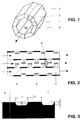
- a gas turbine combustion chamber is shown in simplified form in FIG. 1.
- a convective cooling system is used to cool the combustion chamber wall 1.
- the entire cooling air flows in cooling channels 2 between the outer wall 3 and the combustion chamber wall 1 before it is supplied to the combustion chamber as combustion air.
- connection openings 5 between the cooling channels 2 is advantageously carried out according to the design rule 2 ⁇ sL / A ⁇ 8, that is, the product of the average opening width s between two cooling channels 2 and the cooling channel length L, based on the cross-sectional area A of the cooling channel 2, is in the range greater than 2 and less than 8. If the value falls below the lower limit of this interval, a very large hole can lead to overheating of the cooling channel 2 after the hole. Will the top If the value is significantly exceeded, then a very large hole or a longitudinal slot in one or more cooling channels can lead to such a high air loss that the burners overheat the primary zone of the combustion chamber at full load.
- a local damage site 6 in the form of a small hole can form in the combustion chamber wall 1. Then there is the risk in conventional gas turbine combustion chambers, which are cooled by combined impingement and convection cooling systems or by pure convection cooling systems according to the prior art, that this small damage location 6 leads to major consequential damage because the cooling duct 2 no longer adequately contains cooling air after the hole is supplied.
- connection openings 5 ensures that air can flow into the damaged cooling channel 2 from at least one adjacent channel at every axial position.
- the compensating flow takes place on the outer wall 3 of the combustion chamber.
- cooling film flows are formed on the outer wall 3, which intensely cool the cooling channel 2 and in particular the outer wall 3 in the area of the local damage site 6 (hole) and cool completely. This prevents the hole from growing further.
- the damaged cooling channel is "self-healing".
- the invention is particularly important in the case of thin combustion chamber walls with high thermal loads.
Landscapes
- Engineering & Computer Science (AREA)
- Chemical & Material Sciences (AREA)
- Combustion & Propulsion (AREA)
- Mechanical Engineering (AREA)
- General Engineering & Computer Science (AREA)
- Turbine Rotor Nozzle Sealing (AREA)
Applications Claiming Priority (2)
| Application Number | Priority Date | Filing Date | Title |
|---|---|---|---|
| DE4335413A DE4335413A1 (de) | 1993-10-18 | 1993-10-18 | Verfahren und Vorrichtung zur Kühlung einer Gasturbinenbrennkammer |
| DE4335413 | 1993-10-18 |
Publications (2)
| Publication Number | Publication Date |
|---|---|
| EP0648979A1 true EP0648979A1 (fr) | 1995-04-19 |
| EP0648979B1 EP0648979B1 (fr) | 1999-10-20 |
Family
ID=6500380
Family Applications (1)
| Application Number | Title | Priority Date | Filing Date |
|---|---|---|---|
| EP94115334A Expired - Lifetime EP0648979B1 (fr) | 1993-10-18 | 1994-09-29 | Méthode et moyens pour le refroidissement d'une chambre de combustion d'une turbine à gaz |
Country Status (4)
| Country | Link |
|---|---|
| US (2) | US5615546A (fr) |
| EP (1) | EP0648979B1 (fr) |
| JP (1) | JP3863576B2 (fr) |
| DE (2) | DE4335413A1 (fr) |
Cited By (4)
| Publication number | Priority date | Publication date | Assignee | Title |
|---|---|---|---|---|
| WO2016069599A1 (fr) * | 2014-10-31 | 2016-05-06 | General Electric Company | Ensemble composant de moteur |
| US9957816B2 (en) | 2014-05-29 | 2018-05-01 | General Electric Company | Angled impingement insert |
| US10422235B2 (en) | 2014-05-29 | 2019-09-24 | General Electric Company | Angled impingement inserts with cooling features |
| US10690055B2 (en) | 2014-05-29 | 2020-06-23 | General Electric Company | Engine components with impingement cooling features |
Families Citing this family (5)
| Publication number | Priority date | Publication date | Assignee | Title |
|---|---|---|---|---|
| DE19812236C2 (de) | 1998-03-20 | 2001-10-18 | Daimler Chrysler Ag | Verfahren zur Unterdrückung hochfrequenter Schwingungen an gelenkten Achsen eines Fahrzeugs |
| US8894363B2 (en) | 2011-02-09 | 2014-11-25 | Siemens Energy, Inc. | Cooling module design and method for cooling components of a gas turbine system |
| US8959886B2 (en) * | 2010-07-08 | 2015-02-24 | Siemens Energy, Inc. | Mesh cooled conduit for conveying combustion gases |
| EP2397653A1 (fr) | 2010-06-17 | 2011-12-21 | Siemens Aktiengesellschaft | Segment de plateforme pour porter une aube de guidage pour turbine à gaz et procédé de refroidissement de ce segment |
| US9644511B2 (en) | 2012-09-06 | 2017-05-09 | Mitsubishi Hitachi Power Systems, Ltd. | Combustion gas cooling apparatus, denitration apparatus including the combustion gas cooling apparatus, and combustion gas cooling method |
Citations (6)
| Publication number | Priority date | Publication date | Assignee | Title |
|---|---|---|---|---|
| GB2077635A (en) * | 1980-06-13 | 1981-12-23 | Rolls Royce | Manufacture of laminated material |
| EP0202050A1 (fr) * | 1985-04-29 | 1986-11-20 | Avco Corporation | Structure d'une paroi de chambre de combustion |
| EP0225527A2 (fr) * | 1985-12-02 | 1987-06-16 | Siemens Aktiengesellschaft | Paroi refroidie pour turbines à gaz |
| US4773227A (en) * | 1982-04-07 | 1988-09-27 | United Technologies Corporation | Combustion chamber with improved liner construction |
| EP0489193A1 (fr) * | 1990-12-05 | 1992-06-10 | Asea Brown Boveri Ag | Chambre de combustion pour turbine à gaz |
| US5246341A (en) * | 1992-07-06 | 1993-09-21 | United Technologies Corporation | Turbine blade trailing edge cooling construction |
Family Cites Families (14)
| Publication number | Priority date | Publication date | Assignee | Title |
|---|---|---|---|---|
| US2644302A (en) * | 1948-06-17 | 1953-07-07 | Gen Electric | Combustion chamber having a flat wall liner with oppositely disposed apertures |
| US3408812A (en) * | 1967-02-24 | 1968-11-05 | Gen Electric | Cooled joint construction for combustion wall means |
| SE314558B (fr) * | 1968-10-28 | 1969-09-08 | Stal Laval Turbin Ab | |
| US3777484A (en) * | 1971-12-08 | 1973-12-11 | Gen Electric | Shrouded combustion liner |
| US4071194A (en) * | 1976-10-28 | 1978-01-31 | The United States Of America As Represented By The Secretary Of The Navy | Means for cooling exhaust nozzle sidewalls |
| US4236378A (en) * | 1978-03-01 | 1980-12-02 | General Electric Company | Sectoral combustor for burning low-BTU fuel gas |
| CH633347A5 (de) * | 1978-08-03 | 1982-11-30 | Bbc Brown Boveri & Cie | Gasturbine. |
| GB2033071B (en) * | 1978-10-28 | 1982-07-21 | Rolls Royce | Sheet metal laminate |
| US4302941A (en) * | 1980-04-02 | 1981-12-01 | United Technologies Corporation | Combuster liner construction for gas turbine engine |
| GB2087065B (en) * | 1980-11-08 | 1984-11-07 | Rolls Royce | Wall structure for a combustion chamber |
| GB2118710B (en) * | 1981-12-31 | 1985-05-22 | Secr Defence | Improvements in or relating to combustion chamber wall cooling |
| US4653279A (en) * | 1985-01-07 | 1987-03-31 | United Technologies Corporation | Integral refilmer lip for floatwall panels |
| DE3615226A1 (de) * | 1986-05-06 | 1987-11-12 | Mtu Muenchen Gmbh | Heissgasueberhitzungsschutzeinrichtung fuer gasturbinentriebwerke |
| US5363654A (en) * | 1993-05-10 | 1994-11-15 | General Electric Company | Recuperative impingement cooling of jet engine components |
-
1993
- 1993-10-18 DE DE4335413A patent/DE4335413A1/de not_active Withdrawn
-
1994
- 1994-09-29 EP EP94115334A patent/EP0648979B1/fr not_active Expired - Lifetime
- 1994-09-29 DE DE59408840T patent/DE59408840D1/de not_active Expired - Lifetime
- 1994-10-17 US US08/323,688 patent/US5615546A/en not_active Expired - Lifetime
- 1994-10-17 JP JP25104294A patent/JP3863576B2/ja not_active Expired - Lifetime
-
1996
- 1996-08-20 US US08/699,731 patent/US5651253A/en not_active Expired - Lifetime
Patent Citations (6)
| Publication number | Priority date | Publication date | Assignee | Title |
|---|---|---|---|---|
| GB2077635A (en) * | 1980-06-13 | 1981-12-23 | Rolls Royce | Manufacture of laminated material |
| US4773227A (en) * | 1982-04-07 | 1988-09-27 | United Technologies Corporation | Combustion chamber with improved liner construction |
| EP0202050A1 (fr) * | 1985-04-29 | 1986-11-20 | Avco Corporation | Structure d'une paroi de chambre de combustion |
| EP0225527A2 (fr) * | 1985-12-02 | 1987-06-16 | Siemens Aktiengesellschaft | Paroi refroidie pour turbines à gaz |
| EP0489193A1 (fr) * | 1990-12-05 | 1992-06-10 | Asea Brown Boveri Ag | Chambre de combustion pour turbine à gaz |
| US5246341A (en) * | 1992-07-06 | 1993-09-21 | United Technologies Corporation | Turbine blade trailing edge cooling construction |
Cited By (5)
| Publication number | Priority date | Publication date | Assignee | Title |
|---|---|---|---|---|
| US9957816B2 (en) | 2014-05-29 | 2018-05-01 | General Electric Company | Angled impingement insert |
| US10422235B2 (en) | 2014-05-29 | 2019-09-24 | General Electric Company | Angled impingement inserts with cooling features |
| US10690055B2 (en) | 2014-05-29 | 2020-06-23 | General Electric Company | Engine components with impingement cooling features |
| WO2016069599A1 (fr) * | 2014-10-31 | 2016-05-06 | General Electric Company | Ensemble composant de moteur |
| US10619488B2 (en) | 2014-10-31 | 2020-04-14 | General Electric Company | Engine component assembly |
Also Published As
| Publication number | Publication date |
|---|---|
| DE4335413A1 (de) | 1995-04-20 |
| US5615546A (en) | 1997-04-01 |
| EP0648979B1 (fr) | 1999-10-20 |
| DE59408840D1 (de) | 1999-11-25 |
| JPH07167436A (ja) | 1995-07-04 |
| JP3863576B2 (ja) | 2006-12-27 |
| US5651253A (en) | 1997-07-29 |
Similar Documents
| Publication | Publication Date | Title |
|---|---|---|
| DE10001109B4 (de) | Gekühlte Schaufel für eine Gasturbine | |
| DE60317920T2 (de) | Effusionsgekühlter übergangskanal mit geformten kühllöchern | |
| DE102005025823B4 (de) | Verfahren und Vorrichtung zum Kühlen einer Brennkammerauskleidung und eines Übergangsteils einer Gasturbine | |
| EP0745809B1 (fr) | Générateur de tourbillons pour chambre de combustion | |
| EP1701095B1 (fr) | Ecran thermique | |
| DE69528490T2 (de) | Kühleinrichtung für das Umfangsgehäuse einer Turbine | |
| EP2423599B1 (fr) | Procédé de fonctionnement d'un agencement de brûleur ainsi qu'agencement de brûleur destiné à la mise en oeuvre du procédé | |
| DE69816532T2 (de) | Wärmeübergangsstruktur | |
| DE69803069T2 (de) | Gekühlte brennkammerwand für eine gasturbine | |
| EP0599055B1 (fr) | Chambre de combustion pour turbine à gaz | |
| CH702172A2 (de) | Brennkammer für eine Gasturbine ,mit verbesserter Kühlung. | |
| DE2147135A1 (de) | Brennkammermantel insbesondere für Gasturbinentriebwerke | |
| CH697920A2 (de) | Turbinentriebwerk mit einer Brennkammerauskleidung mit wirbelluftgekühltem hinterem Ende und Kühlverfahren. | |
| DE3231689A1 (de) | Mehrfach prallgekuehltes gebilde, insbesondere ummantelung eines gasstroemungsweges | |
| DE10064264B4 (de) | Anordnung zur Kühlung eines Bauteils | |
| EP2154431A2 (fr) | Machine thermique | |
| DE2617999A1 (de) | Kuehlring fuer brennkammern | |
| DE4443864A1 (de) | Gek}hltes Wandteil | |
| EP0718561A2 (fr) | Brûleur | |
| EP0640745B1 (fr) | Procédé de refroidissement d'un composant | |
| EP0718558A2 (fr) | Brûleur | |
| EP0648979B1 (fr) | Méthode et moyens pour le refroidissement d'une chambre de combustion d'une turbine à gaz | |
| EP0892149A1 (fr) | Système de refroidissement pour le bord d'attac d'une aube creuse pour turbine à gaz | |
| EP0489193A1 (fr) | Chambre de combustion pour turbine à gaz | |
| DE60225411T2 (de) | Flammrohr oder Bekleidung für die Brennkammer einer Gasturbine mit niedriger Schadstoffemission |
Legal Events
| Date | Code | Title | Description |
|---|---|---|---|
| PUAI | Public reference made under article 153(3) epc to a published international application that has entered the european phase |
Free format text: ORIGINAL CODE: 0009012 |
|
| AK | Designated contracting states |
Kind code of ref document: A1 Designated state(s): DE FR GB |
|
| 17P | Request for examination filed |
Effective date: 19950916 |
|
| 17Q | First examination report despatched |
Effective date: 19961030 |
|
| RAP1 | Party data changed (applicant data changed or rights of an application transferred) |
Owner name: ASEA BROWN BOVERI AG |
|
| GRAG | Despatch of communication of intention to grant |
Free format text: ORIGINAL CODE: EPIDOS AGRA |
|
| GRAG | Despatch of communication of intention to grant |
Free format text: ORIGINAL CODE: EPIDOS AGRA |
|
| GRAH | Despatch of communication of intention to grant a patent |
Free format text: ORIGINAL CODE: EPIDOS IGRA |
|
| GRAH | Despatch of communication of intention to grant a patent |
Free format text: ORIGINAL CODE: EPIDOS IGRA |
|
| GRAA | (expected) grant |
Free format text: ORIGINAL CODE: 0009210 |
|
| AK | Designated contracting states |
Kind code of ref document: B1 Designated state(s): DE FR GB |
|
| REF | Corresponds to: |
Ref document number: 59408840 Country of ref document: DE Date of ref document: 19991125 |
|
| ET | Fr: translation filed | ||
| RAP2 | Party data changed (patent owner data changed or rights of a patent transferred) |
Owner name: ABB ALSTOM POWER (SCHWEIZ) AG |
|
| GBT | Gb: translation of ep patent filed (gb section 77(6)(a)/1977) |
Effective date: 20000223 |
|
| REG | Reference to a national code |
Ref country code: GB Ref legal event code: 732E |
|
| PLBE | No opposition filed within time limit |
Free format text: ORIGINAL CODE: 0009261 |
|
| STAA | Information on the status of an ep patent application or granted ep patent |
Free format text: STATUS: NO OPPOSITION FILED WITHIN TIME LIMIT |
|
| 26N | No opposition filed | ||
| REG | Reference to a national code |
Ref country code: GB Ref legal event code: IF02 |
|
| REG | Reference to a national code |
Ref country code: FR Ref legal event code: TP Ref country code: FR Ref legal event code: CD |
|
| REG | Reference to a national code |
Ref country code: DE Ref legal event code: R082 Ref document number: 59408840 Country of ref document: DE Representative=s name: ROESLER, UWE, DIPL.-PHYS.UNIV., DE Effective date: 20120621 Ref country code: DE Ref legal event code: R081 Ref document number: 59408840 Country of ref document: DE Owner name: ALSTOM TECHNOLOGY LTD., CH Free format text: FORMER OWNER: ALSTOM, PARIS, FR Effective date: 20120621 |
|
| REG | Reference to a national code |
Ref country code: GB Ref legal event code: 732E Free format text: REGISTERED BETWEEN 20120802 AND 20120808 |
|
| REG | Reference to a national code |
Ref country code: FR Ref legal event code: TP Owner name: ALSTOM TECHNOLOGY LTD., CH Effective date: 20120918 |
|
| PGFP | Annual fee paid to national office [announced via postgrant information from national office to epo] |
Ref country code: GB Payment date: 20130827 Year of fee payment: 20 Ref country code: FR Payment date: 20130826 Year of fee payment: 20 |
|
| PGFP | Annual fee paid to national office [announced via postgrant information from national office to epo] |
Ref country code: DE Payment date: 20130930 Year of fee payment: 20 |
|
| REG | Reference to a national code |
Ref country code: DE Ref legal event code: R071 Ref document number: 59408840 Country of ref document: DE |
|
| REG | Reference to a national code |
Ref country code: GB Ref legal event code: PE20 Expiry date: 20140928 |
|
| PG25 | Lapsed in a contracting state [announced via postgrant information from national office to epo] |
Ref country code: DE Free format text: LAPSE BECAUSE OF EXPIRATION OF PROTECTION Effective date: 20140930 |
|
| PG25 | Lapsed in a contracting state [announced via postgrant information from national office to epo] |
Ref country code: GB Free format text: LAPSE BECAUSE OF EXPIRATION OF PROTECTION Effective date: 20140928 |