EP0649263A2 - Magnétoscope équipé d'un projecteur à cristaux liquides - Google Patents
Magnétoscope équipé d'un projecteur à cristaux liquides Download PDFInfo
- Publication number
- EP0649263A2 EP0649263A2 EP94402280A EP94402280A EP0649263A2 EP 0649263 A2 EP0649263 A2 EP 0649263A2 EP 94402280 A EP94402280 A EP 94402280A EP 94402280 A EP94402280 A EP 94402280A EP 0649263 A2 EP0649263 A2 EP 0649263A2
- Authority
- EP
- European Patent Office
- Prior art keywords
- image
- rear screen
- screen
- liquid crystal
- video tape
- Prior art date
- Legal status (The legal status is an assumption and is not a legal conclusion. Google has not performed a legal analysis and makes no representation as to the accuracy of the status listed.)
- Withdrawn
Links
Images


Classifications
-
- G—PHYSICS
- G11—INFORMATION STORAGE
- G11B—INFORMATION STORAGE BASED ON RELATIVE MOVEMENT BETWEEN RECORD CARRIER AND TRANSDUCER
- G11B31/00—Arrangements for the associated working of recording or reproducing apparatus with related apparatus
-
- H—ELECTRICITY
- H04—ELECTRIC COMMUNICATION TECHNIQUE
- H04N—PICTORIAL COMMUNICATION, e.g. TELEVISION
- H04N5/00—Details of television systems
- H04N5/76—Television signal recording
- H04N5/78—Television signal recording using magnetic recording
- H04N5/782—Television signal recording using magnetic recording on tape
-
- H—ELECTRICITY
- H04—ELECTRIC COMMUNICATION TECHNIQUE
- H04N—PICTORIAL COMMUNICATION, e.g. TELEVISION
- H04N5/00—Details of television systems
- H04N5/74—Projection arrangements for image reproduction, e.g. using eidophor
- H04N5/7416—Projection arrangements for image reproduction, e.g. using eidophor involving the use of a spatial light modulator, e.g. a light valve, controlled by a video signal
- H04N5/7441—Projection arrangements for image reproduction, e.g. using eidophor involving the use of a spatial light modulator, e.g. a light valve, controlled by a video signal the modulator being an array of liquid crystal cells
-
- H—ELECTRICITY
- H04—ELECTRIC COMMUNICATION TECHNIQUE
- H04N—PICTORIAL COMMUNICATION, e.g. TELEVISION
- H04N9/00—Details of colour television systems
- H04N9/79—Processing of colour television signals in connection with recording
- H04N9/80—Transformation of the television signal for recording, e.g. modulation, frequency changing; Inverse transformation for playback
- H04N9/82—Transformation of the television signal for recording, e.g. modulation, frequency changing; Inverse transformation for playback the individual colour picture signal components being recorded simultaneously only
- H04N9/83—Transformation of the television signal for recording, e.g. modulation, frequency changing; Inverse transformation for playback the individual colour picture signal components being recorded simultaneously only the recorded chrominance signal occupying a frequency band under the frequency band of the recorded brightness signal
Definitions
- the present invention relates to a combination of a projector using liquid crystal display (LCD) and a video tape recorder (VTR), and more particularly to a VTR equipped with a color LCD projector.
- LCD liquid crystal display
- VTR video tape recorder
- LCD projectors are widely used as application of LCDs. Since the cost per inch of a screen is high, an LCD projector for a large screen is very expensive. As a result, such an expensive large screen type LCD projector is mainly used only for business purposes. Moreover, most of large screen type LCD projectors have a fixed type construction, not a portable type, because they require a large lens size.
- compact LCD projectors of the portable type are commercially available.
- Such a compact LCD projector allows the user to view an image photographed by a video cassette recorder equipped with a camera integral therewith on a trip even when there is no TV by projecting the image onto a wall surface or a screen. Since the compact LCD projector uses a LCD having a size of 0.7 to 1 inch, it is convenient to be carried by the user.
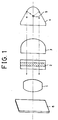
- FIG. 1 is a schematic view for explaining operation of an LCD projector.
- the reference numeral 1 denotes a projection lens, 2 an LCD panel, 3 a condensing lens, 4 a reflector, 5 a halogen lamp, and 8 a screen such as a wall surface.
- Liquid crystal does not emit light by itself and receives light from outside to display a video signal using a variation in reflectivity and transmittivity of a liquid crystal cell.
- the LCD projector achieves a picture reproduction using a projection of a pattern of light transmitting through the liquid crystal panel 2 on a front surface of the liquid crystal panel 2.
- the parallel light incident on the liquid crystal panel 2 is then subjected to a spatial modulation appropriate to video signals.
- the light which has been subjected to the spatial modulation then enters the projection lens 1 which, in turn, projects the light onto the screen 8 arranged in front of the projection lens 1, so that a picture is displayed.
- FIG. 2 is a perspective view of the appearance of the LCD projector having the arrangement of FIG. 1.
- the reference numeral 1 denotes the projection lens shown in FIG. 1, 7 a focusing ring, and 10 a cassette insertion/extraction opening of a VTR.
- the LCD projector of the illustrated type is commercially available in the form of a single product to be used as an exclusive unit for the projection.
- various wirings such as couplings and power supply lines are connected between the LCD projector and the VTR.
- wirings are reduced in number, a convenience in use is improved.
- the wirings are increased in number or in length, a degradation of video signals may easily occur due to generation of noise.
- processes of separating and composing video signals between the appliances are increased in number, thereby causing the signals to be easily degraded.
- a compact LCD projector is frequently used for reproduction of VTR.
- the LCD projector should have wirings for video signals to be supplied from the VTR. Wirings for audio signals and electric power should be also provided.
- the above case encounters the complexity of wirings.
- the LCD projector is integral with the VTR in order to eliminate the complexity of wirings, a convenience in use is obtained.
- an object of the invention is to solve the above-mentioned problem encountered in the prior art and, thus, to provide a VTR equipped with an LCD projector integral therewith, capable of eliminating the complexity of wirings and preventing degradation of video signals.
- the present invention provides a video tape recorder equipped with a liquid crystal display projector for projecting an image onto a front screen such as a wall surface, comprising: a rear screen disposed on a front panel of a body of the video tape recorder and constructed to be openable and closable for the liquid crystal display projector projecting the image; detecting means for detecting an openable or closable state of the rear screen; image inverting means for laterally inverting a direction of the image to be projected onto the rear screen; the rear screen being opened when a viewer observes the image projected on the front screen, while being closed when the viewer observes the image projected on the rear screen; the detecting means informing the image inverting means of the closed state of the rear screen; and the image inverting means laterally inverting the image to be projected onto the rear screen upon receiving the information.
- the image inverting means is adapted to inversely scan a string of pulses for driving a liquid crystal display panel and thereby obtain an inverted image.
- the present invention provides a video tape recorder equipped with a liquid crystal display projector for projecting an image onto a front screen such as a wall surface, comprising: a rear screen disposed on a top panel of a body of the video tape recorder and constructed for the liquid crystal display projector projecting the image; reflection means for projecting the image onto the rear screen, the reflection means being movable between a laid-down position and a stand-up position; and the reflection means allowing the image to be projected onto the front screen by the movement thereof to the laid-down position when a viewer desires to observe the image projected onto the front screen, while allowing the image to be projected onto the rear screen by the movement thereof to the stand-up position when the viewer desires to observe the image projected onto the rear screen.
- the reflection means comprises a plane mirror and a pivot shaft for pivoting the plane mirror.
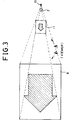
- FIG. 3 is a schematic view explaining the basic concept of the present invention where an LCD projector is integral with a VTR.
- the reference numeral 2 denotes an LCD panel, 8 a front screen, 11 a first rear screen installed in the VTR, and 13 a condensing lens including a light source.
- the condensing lens 13, LCD panel 2 and first rear screen 11 are installed in the VTR.
- a projection lens 1 (FIGS. 6A and 6B) is also installed in the VTR.
- the image projected onto the front screen 8 is depicted in the form of an arrow so as to clearly illustrate the lateral inversion between the image on the front screen 8 and the image on the first rear screen 11 both viewed by a viewer who is positioned between the front screen 8 and the first rear screen 11.
- the VTR operates to reproduce video signals in a confined room such as the interior of a car
- the viewer can view a reproduced image projected onto the first rear screen 11 disposed on a front panel of the VTR or a second rear screen 14 disposed on a top panel of the VTR.
- the arrow of the image viewed by the viewer is opposite in direction to that of the image on the front screen 8 viewed by the viewer in accordance with the present invention.
- Such a lateral image inversion between the first rear screen 11 and the front screen 8 is easily achieved by a lateral image inversion function of an LCD driving unit which will be described hereinafter.
- the image inversion may be achieved by a plane mirror, as shown in FIG. 6A.
- the first rear screen 11 is constructed to move between an opened position and a closed position so that it can meet the construction of the LCD projector integral with the VTR.
- the first rear screen 11 When the viewer desires to view an image projected onto the front screen 8 such as a wall surface, the first rear screen 11 is positioned at its opened position so that light can be directly projected on the screen 8.
- the first rear screen 11 When the viewer desires to view an image projected onto the panel of VTR, the first rear screen 11 is positioned at its closed position so that light can be projected on the screen 11. In this case, a lateral image inversion is obtained in a manner as mentioned above.
- the closing of the first rear screen 11 is detected by a closing detecting unit.
- the closing detecting unit detects the closed state of the first rear screen 11, it generates a lateral image inversion signal to the LCD driving unit so as to achieve an automatic lateral image inversion.
- FIG. 4 is a perspective view illustrating a fixed type VTR equipped with the LCD projector integral therewith in accordance with the present invention.
- FIG. 5 is a perspective view illustrating a potable type VTR equipped with the LCD projector integral therewith in accordance with the present invention.
- FIGS. 6A and 6B are a schematic sectional view and a schematic perspective view respectively illustrating the case wherein the second rear screen is used.
- FIG. 7 is a block diagram of a reproduction circuit equipped in either type of VTR.
- FIG. 8 is a block diagram of the LCD driving unit equipped in either type of VTR.
- the reference numeral denotes the fixed type VTR equipped with the LCD projector, 10 an insertion/extraction opening for a video tape cassette, 11 the first rear screen, and 14 the second rear screen.
- the viewer can select optionally one of the first rear screen 11, the second rear screen 14 and the front screen 8 to view an image projected onto the selected screen.
- the plane mirror 15 is positioned at its horizontal position, as shown in FIG. 6B.
- the first rear screen 11 is also positioned at its opened position.
- the first rear screen 11 is positioned at its closed position under the condition that the plane mirror 15 is positioned at its horizontal position.
- the lateral image inversion is achieved by an image inverting unit.
- the reference numeral 12 denotes the potable type VTR equipped with the LCD projector integral therewith.
- the VTR shown in FIG. 5 has the same construction as that shown in FIG. 4, except that it is designed to have a compact size. Therefore, no description of the potable type VTR will be made.
- FIGS. 6A and 6B show an inner construction of the VTR of FIG. 4 or 5 including the second rear screen disposed on a top panel of a VTR body.
- the reference numeral 1 denotes the projection lens, 15 the plane mirror, and 16 a pivot shaft of the plane mirror 15.
- the plane mirror 15 and the pivot shaft 16 constitute a reflection unit.
- the plane mirror 15 is disposed in front of the projection lens 1 such that it can pivot about the pivot shaft 16.
- the reflection angle of the plane mirror 15 is adjusted to reflect light beams emerging from the projection lens 1 such that the light beams are vertically projected onto the second rear screen 14, the viewer can view a small-sized picture displayed on the top panel of the VTR body.
- the plane mirror 15 is laid down in the direction indicated by the arrow in FIG. 6B.
- the image emerging from the projection lens 1 is projected onto the front screen 8.
- the case using the first rear screen requires the image inverting unit for reversing the scanning direction of the LCD panel
- the case of FIGS. 6A and 6B using the second rear screen installed on the top panel of the VCR body has an advantage that the image inversion performed in the LCD driving unit is not required. This is because the plane mirror 15 constituting a part of the image reflection unit inverts the image laterally.
- the reference character T denotes a magnetic tape
- the reference numeral 20 denotes a magnetic head
- 21 a pre-amplifier
- 22 a high-pass filter
- 23 a luminance signal processing circuit
- 24 a low-pass filter
- 25 a color signal processing circuit
- 26 an adder.
- a video signal recorded on the magnetic tape T is converted into an electrical signal by the magnetic head 20 and the preamplifier 21 in a reproduction operation of the VTR.
- the electrical signal is then sent to both the high-pass filter 22 and the low-pass filter 23 which extract a FM luminance signal and a low-band-converted color signal from the received signal, respectively.
- the FM luminance signal and the color signal are then converted into an original luminance signal Y and an original color signal C in the luminance signal processing circuit 23 and the color signal processing circuit 25, respectively.
- Both the recovered luminance signal Y and the recovered color signal C are sent to the adder 26 which, in turn, generates a composite video signal Y+C.
- the unit for driving the LCD panel 35 is shown.
- the LCD driving unit includes a terminal 30 for receiving the composite video signal Y+C from the adder 26, and a drive pulse control unit 36 for generating a drive pulse D made from the composite video signal Y+C.
- the reference numeral 31 denotes a low-pass filter, 32 a band-pass filter, 33 a demodulator, and 34 a matrix circuit for composing signals received thereto.
- the drive pulse control unit 36 makes R, G and B signals made from the composite video signal Y+C correspond to R, G and B pixels of the LCD panle 35 (corresponding to the element denoted by the reference numeral 2 in FIG. 1) by generating drive pulses corresponding to the pixels, respectively.
- the drive pulse control unit 36 also varies the transmittivity of the LCD panel, based on the video signal. As mentioned above, the lateral image inversion is made between the first rear screen 11 and the front screen 8. This image inversion is achieved by inverting a string of pulses driving the LCD.
- the LCD projector and the VTR are separated from each other, thereby requiring a wiring for connecting them with each other.
- the LCD projector is integral with the VTR.
- the luminance-processing output and color-processing output of the VTR can be directly connected to the output of the low-pass filter 31 and band-pass filter 32 of the LCD projector, respectively. This means no requirement of any outer wiring.
- the VTR of the present invention has an audio speaker and a headphone terminal.
- a focusing ring for the LCD projector is also provided.
- the present invention provides a VTR equipped with an LCD projector integral therewith, capable of simplifying its wiring including signal lines and power supply lines. Since a rear screen is installed on a front panel of the VTR in accordance with the present invention, the VTR can be used to achieve a small-sized image display. Furthermore, since the rear screen is constructed to be openable and closable, it is possible to project an image onto a large screen such as a wall surface. Accordingly, the value of using the LCD projector is greatly enhanced.
Landscapes
- Engineering & Computer Science (AREA)
- Multimedia (AREA)
- Signal Processing (AREA)
- Chemical & Material Sciences (AREA)
- Crystallography & Structural Chemistry (AREA)
- Transforming Electric Information Into Light Information (AREA)
- Projection Apparatus (AREA)
- Liquid Crystal (AREA)
- Signal Processing Not Specific To The Method Of Recording And Reproducing (AREA)
Applications Claiming Priority (2)
| Application Number | Priority Date | Filing Date | Title |
|---|---|---|---|
| JP256906/93 | 1993-10-14 | ||
| JP5256906A JPH07113997A (ja) | 1993-10-14 | 1993-10-14 | 液晶プロジェクター内蔵vtr |
Publications (2)
| Publication Number | Publication Date |
|---|---|
| EP0649263A2 true EP0649263A2 (fr) | 1995-04-19 |
| EP0649263A3 EP0649263A3 (fr) | 1995-06-21 |
Family
ID=17299035
Family Applications (1)
| Application Number | Title | Priority Date | Filing Date |
|---|---|---|---|
| EP94402280A Withdrawn EP0649263A3 (fr) | 1993-10-14 | 1994-10-11 | Magnétoscope équipé d'un projecteur à cristaux liquides. |
Country Status (4)
| Country | Link |
|---|---|
| US (1) | US5461437A (fr) |
| EP (1) | EP0649263A3 (fr) |
| JP (1) | JPH07113997A (fr) |
| KR (1) | KR0152779B1 (fr) |
Cited By (5)
| Publication number | Priority date | Publication date | Assignee | Title |
|---|---|---|---|---|
| WO1998026404A3 (fr) * | 1996-12-13 | 1998-10-08 | United Technologies Automotive | Afficheur ambivalent |
| EP1100277A1 (fr) * | 1999-11-12 | 2001-05-16 | International Business Machines Corporation | Appareils avec projecteur intégré |
| WO2004105389A1 (fr) * | 2003-05-23 | 2004-12-02 | Il & Fs Education & Technology Services Ltd. | Appareil portable de projection |
| EP1436668A4 (fr) * | 2001-09-20 | 2005-08-17 | Digislide Internat Pty Ltd | Dispositif de projection d'images decoupables utilise avec des stations d'accueil |
| CN101344708B (zh) * | 2007-07-13 | 2010-06-16 | 精工爱普生株式会社 | 投影仪 |
Families Citing this family (21)
| Publication number | Priority date | Publication date | Assignee | Title |
|---|---|---|---|---|
| JP3380083B2 (ja) * | 1994-08-12 | 2003-02-24 | ペンタックス株式会社 | 投影装置及び投影装置のピント調整方法 |
| KR960013009A (ko) * | 1994-09-15 | 1996-04-20 | 이헌조 | 슬라이드 겸용 프로젝터 |
| US5658063A (en) * | 1995-11-02 | 1997-08-19 | Texas Instruments Incorporated | Monitorless video projection system |
| KR970057645A (ko) * | 1995-12-15 | 1997-07-31 | 구자홍 | 실내조명기능을 갖는 프로젝터 |
| US5826962A (en) * | 1997-04-30 | 1998-10-27 | Minnesota Mining And Manufacturing Company | LCD integrated/overhead projector |
| KR20000039089A (ko) * | 1998-12-11 | 2000-07-05 | 구자홍 | 뒤집힘 상태를 자동 감지하여 반전처리하는 엘씨디 프로젝터 |
| WO2001096940A1 (fr) | 2000-06-13 | 2001-12-20 | Derryberry Eddie W | Dispositif electronique de projection d'image |
| US6489934B1 (en) * | 2000-07-07 | 2002-12-03 | Judah Klausner | Cellular phone with built in optical projector for display of data |
| US6443574B1 (en) | 2001-07-24 | 2002-09-03 | Visteon Global Technologies, Inc. | Removable vehicle entertainment system |
| US6773114B2 (en) * | 2001-12-07 | 2004-08-10 | Nokia Corporation | Portable multimode display device |
| AU2003218102A1 (en) * | 2002-03-13 | 2003-09-29 | Timothy J. Denmeade | Digital media source integral with microprocessor, image projection device and audio component as a self-contained system |
| US6935754B2 (en) * | 2003-05-14 | 2005-08-30 | In Focus Corporation | User-interface for a projection device |
| US7290885B2 (en) * | 2003-05-14 | 2007-11-06 | Infocus Corporation | User-interface for projection devices |
| TW200527110A (en) * | 2003-10-20 | 2005-08-16 | Johnson Res And Dev Co Inc | Portable multimedia projection system |
| JP4222277B2 (ja) * | 2004-09-02 | 2009-02-12 | セイコーエプソン株式会社 | プロジェクタ |
| US7431465B2 (en) * | 2005-09-09 | 2008-10-07 | Sony Corporation | Apparatus and method to display images from projection device mounted in vertical position |
| US20070242225A1 (en) * | 2005-10-18 | 2007-10-18 | Maureen Bragg | Sleep mode display system |
| US9324253B2 (en) * | 2005-12-06 | 2016-04-26 | Dolby Laboratories Licensing Corporation | Modular electronic displays |
| JP2010078634A (ja) * | 2008-09-24 | 2010-04-08 | Seiko Epson Corp | プロジェクタ |
| USD627331S1 (en) * | 2009-03-06 | 2010-11-16 | Ethell Barbara A | Audio visual photograph display box |
| US8342691B2 (en) * | 2010-02-03 | 2013-01-01 | International Business Machines Corporation | Information technology system with micro projector display |
Family Cites Families (9)
| Publication number | Priority date | Publication date | Assignee | Title |
|---|---|---|---|---|
| US4093363A (en) * | 1975-11-03 | 1978-06-06 | Rollei-Werke Franke & Heidecke | Motion picture projector |
| FR2552896B1 (fr) * | 1983-09-30 | 1986-07-04 | Prestinox | Appareil mixte de projection et de retroprojection de diapositives |
| JPH0213071A (ja) * | 1988-06-30 | 1990-01-17 | Matsushita Electric Ind Co Ltd | カメラ一体形ビデオテープレコーダ |
| JPH03187681A (ja) * | 1989-12-18 | 1991-08-15 | Nec Home Electron Ltd | カメラ一体型ビデオテープレコーダ |
| JP3157508B2 (ja) * | 1990-03-30 | 2001-04-16 | 株式会社日立製作所 | ビデオ液晶プロジェクタ |
| JP2551854Y2 (ja) * | 1990-05-24 | 1997-10-27 | 富士写真フイルム株式会社 | 液晶プロジェクター |
| ES2055944T3 (es) * | 1991-07-15 | 1994-09-01 | Reflecta Gmbh Foto | Proyector de diapositivas para la proyeccion sobre pantalla y para retroproyeccion. |
| KR960002207B1 (ko) * | 1991-12-30 | 1996-02-13 | 엘지전자주식회사 | 포터블 엘씨디 프로젝터 |
| JPH05203902A (ja) * | 1992-01-23 | 1993-08-13 | Fuji Photo Film Co Ltd | プロジェクタ付きカメラ一体型vtr |
-
1993
- 1993-10-14 JP JP5256906A patent/JPH07113997A/ja not_active Withdrawn
-
1994
- 1994-09-24 KR KR1019940024090A patent/KR0152779B1/ko not_active Expired - Fee Related
- 1994-10-11 EP EP94402280A patent/EP0649263A3/fr not_active Withdrawn
- 1994-10-11 US US08/321,088 patent/US5461437A/en not_active Expired - Fee Related
Cited By (6)
| Publication number | Priority date | Publication date | Assignee | Title |
|---|---|---|---|---|
| WO1998026404A3 (fr) * | 1996-12-13 | 1998-10-08 | United Technologies Automotive | Afficheur ambivalent |
| US5867133A (en) * | 1996-12-13 | 1999-02-02 | Ut Automotive Dearborn, Inc. | Dual use display |
| EP1100277A1 (fr) * | 1999-11-12 | 2001-05-16 | International Business Machines Corporation | Appareils avec projecteur intégré |
| EP1436668A4 (fr) * | 2001-09-20 | 2005-08-17 | Digislide Internat Pty Ltd | Dispositif de projection d'images decoupables utilise avec des stations d'accueil |
| WO2004105389A1 (fr) * | 2003-05-23 | 2004-12-02 | Il & Fs Education & Technology Services Ltd. | Appareil portable de projection |
| CN101344708B (zh) * | 2007-07-13 | 2010-06-16 | 精工爱普生株式会社 | 投影仪 |
Also Published As
| Publication number | Publication date |
|---|---|
| KR950012448A (ko) | 1995-05-16 |
| US5461437A (en) | 1995-10-24 |
| JPH07113997A (ja) | 1995-05-02 |
| KR0152779B1 (ko) | 1998-10-15 |
| EP0649263A3 (fr) | 1995-06-21 |
Similar Documents
| Publication | Publication Date | Title |
|---|---|---|
| US5461437A (en) | Video tape recorder equipped with liquid crystal display projector | |
| US5258844A (en) | Video camera apparatus having an image projection function | |
| GB2266427A (en) | Video camera with both view finding and projecting function | |
| JPH0365879A (ja) | 投影表示機能一体型カメラ | |
| US5488492A (en) | Apparatus for adjusting color tone of image to be recorded | |
| US5097344A (en) | Apparatus for recording and playing back still video images | |
| JP3306081B2 (ja) | 映像再生装置 | |
| JPS62207073A (ja) | 映像装置 | |
| JP2004236104A (ja) | 撮像装置 | |
| GB2257597A (en) | Camcorder displays foreground and background scenes | |
| JPH0213071A (ja) | カメラ一体形ビデオテープレコーダ | |
| JPH10215396A (ja) | 電子撮像装置 | |
| JP3505088B2 (ja) | 撮像装置 | |
| JPH0364170A (ja) | カメラ装置及びカメラ録画システム | |
| JPH0378374A (ja) | 映像再生方式 | |
| JPH08307745A (ja) | 液晶モニタ付きビデオカメラ及びtvプロジェクタアダプタ | |
| JPH04252572A (ja) | 投射兼用型ビューファインダ | |
| JPH06237429A (ja) | スクリーン装置及びフロント投射型プロジェクタシステム | |
| KR950006039B1 (ko) | 영상투사 디스플레이 기능을 갖는 비디오카메라 | |
| JPS6298895A (ja) | テレビカメラ | |
| JPH06237403A (ja) | 映像記録再生システム | |
| EP0550038A1 (fr) | Rétroprojecteur à sortie vidéo | |
| JPH0322765A (ja) | カメラー体型画像記録再生装置 | |
| KR0135168B1 (ko) | 프로젝트 기능을 갖는 무비 카메라 시스템 | |
| JPH0641284U (ja) | ビデオプロジェクタ |
Legal Events
| Date | Code | Title | Description |
|---|---|---|---|
| PUAI | Public reference made under article 153(3) epc to a published international application that has entered the european phase |
Free format text: ORIGINAL CODE: 0009012 |
|
| AK | Designated contracting states |
Kind code of ref document: A2 Designated state(s): DE FR GB NL |
|
| PUAL | Search report despatched |
Free format text: ORIGINAL CODE: 0009013 |
|
| AK | Designated contracting states |
Kind code of ref document: A3 Designated state(s): DE FR GB NL |
|
| RAP1 | Party data changed (applicant data changed or rights of an application transferred) |
Owner name: LG ELECTRONICS INC. |
|
| 17P | Request for examination filed |
Effective date: 19951123 |
|
| 17Q | First examination report despatched |
Effective date: 19980205 |
|
| STAA | Information on the status of an ep patent application or granted ep patent |
Free format text: STATUS: THE APPLICATION IS DEEMED TO BE WITHDRAWN |
|
| 18D | Application deemed to be withdrawn |
Effective date: 19980818 |