EP0649806B1 - Appareil et procédé pour charger des rouleaux de bande dans un récipient - Google Patents
Appareil et procédé pour charger des rouleaux de bande dans un récipient Download PDFInfo
- Publication number
- EP0649806B1 EP0649806B1 EP94116038A EP94116038A EP0649806B1 EP 0649806 B1 EP0649806 B1 EP 0649806B1 EP 94116038 A EP94116038 A EP 94116038A EP 94116038 A EP94116038 A EP 94116038A EP 0649806 B1 EP0649806 B1 EP 0649806B1
- Authority
- EP
- European Patent Office
- Prior art keywords
- axis
- chamber
- stack
- support member
- head
- Prior art date
- Legal status (The legal status is an assumption and is not a legal conclusion. Google has not performed a legal analysis and makes no representation as to the accuracy of the status listed.)
- Expired - Lifetime
Links
- 238000000034 method Methods 0.000 title description 7
- 238000004519 manufacturing process Methods 0.000 description 3
- 238000004806 packaging method and process Methods 0.000 description 3
- 238000010276 construction Methods 0.000 description 2
- 238000013459 approach Methods 0.000 description 1
- 230000005484 gravity Effects 0.000 description 1
Images



Classifications
-
- G—PHYSICS
- G03—PHOTOGRAPHY; CINEMATOGRAPHY; ANALOGOUS TECHNIQUES USING WAVES OTHER THAN OPTICAL WAVES; ELECTROGRAPHY; HOLOGRAPHY
- G03B—APPARATUS OR ARRANGEMENTS FOR TAKING PHOTOGRAPHS OR FOR PROJECTING OR VIEWING THEM; APPARATUS OR ARRANGEMENTS EMPLOYING ANALOGOUS TECHNIQUES USING WAVES OTHER THAN OPTICAL WAVES; ACCESSORIES THEREFOR
- G03B27/00—Photographic printing apparatus
- G03B27/32—Projection printing apparatus, e.g. enlarger, copying camera
- G03B27/52—Details
- G03B27/58—Baseboards, masking frames, or other holders for the sensitive material
- G03B27/587—Handling photosensitive webs
- G03B27/588—Supply rolls; Cutting arrangements
-
- B—PERFORMING OPERATIONS; TRANSPORTING
- B65—CONVEYING; PACKING; STORING; HANDLING THIN OR FILAMENTARY MATERIAL
- B65H—HANDLING THIN OR FILAMENTARY MATERIAL, e.g. SHEETS, WEBS, CABLES
- B65H19/00—Changing the web roll
- B65H19/10—Changing the web roll in unwinding mechanisms or in connection with unwinding operations
- B65H19/12—Lifting, transporting, or inserting the web roll; Removing empty core
- B65H19/123—Lifting, transporting, or inserting the web roll; Removing empty core with cantilever supporting arrangements
-
- B—PERFORMING OPERATIONS; TRANSPORTING
- B65—CONVEYING; PACKING; STORING; HANDLING THIN OR FILAMENTARY MATERIAL
- B65H—HANDLING THIN OR FILAMENTARY MATERIAL, e.g. SHEETS, WEBS, CABLES
- B65H2301/00—Handling processes for sheets or webs
- B65H2301/40—Type of handling process
- B65H2301/41—Winding, unwinding
- B65H2301/413—Supporting web roll
- B65H2301/4132—Cantilever arrangement
- B65H2301/41322—Cantilever arrangement pivoting movement of roll support
-
- B—PERFORMING OPERATIONS; TRANSPORTING
- B65—CONVEYING; PACKING; STORING; HANDLING THIN OR FILAMENTARY MATERIAL
- B65H—HANDLING THIN OR FILAMENTARY MATERIAL, e.g. SHEETS, WEBS, CABLES
- B65H2301/00—Handling processes for sheets or webs
- B65H2301/40—Type of handling process
- B65H2301/41—Winding, unwinding
- B65H2301/414—Winding
- B65H2301/4148—Winding slitting
-
- B—PERFORMING OPERATIONS; TRANSPORTING
- B65—CONVEYING; PACKING; STORING; HANDLING THIN OR FILAMENTARY MATERIAL
- B65H—HANDLING THIN OR FILAMENTARY MATERIAL, e.g. SHEETS, WEBS, CABLES
- B65H2301/00—Handling processes for sheets or webs
- B65H2301/40—Type of handling process
- B65H2301/41—Winding, unwinding
- B65H2301/417—Handling or changing web rolls
- B65H2301/4171—Handling web roll
- B65H2301/4173—Handling web roll by central portion, e.g. gripping central portion
-
- B—PERFORMING OPERATIONS; TRANSPORTING
- B65—CONVEYING; PACKING; STORING; HANDLING THIN OR FILAMENTARY MATERIAL
- B65H—HANDLING THIN OR FILAMENTARY MATERIAL, e.g. SHEETS, WEBS, CABLES
- B65H2405/00—Parts for holding the handled material
- B65H2405/40—Holders, supports for rolls
- B65H2405/42—Supports for rolls fully removable from the handling machine
- B65H2405/422—Trolley, cart, i.e. support movable on floor
-
- B—PERFORMING OPERATIONS; TRANSPORTING
- B65—CONVEYING; PACKING; STORING; HANDLING THIN OR FILAMENTARY MATERIAL
- B65H—HANDLING THIN OR FILAMENTARY MATERIAL, e.g. SHEETS, WEBS, CABLES
- B65H2405/00—Parts for holding the handled material
- B65H2405/40—Holders, supports for rolls
- B65H2405/46—Grippers for bobbins, i.e. rolls
- B65H2405/461—Grippers for bobbins, i.e. rolls center gripper (inside the core)
-
- Y—GENERAL TAGGING OF NEW TECHNOLOGICAL DEVELOPMENTS; GENERAL TAGGING OF CROSS-SECTIONAL TECHNOLOGIES SPANNING OVER SEVERAL SECTIONS OF THE IPC; TECHNICAL SUBJECTS COVERED BY FORMER USPC CROSS-REFERENCE ART COLLECTIONS [XRACs] AND DIGESTS
- Y10—TECHNICAL SUBJECTS COVERED BY FORMER USPC
- Y10S—TECHNICAL SUBJECTS COVERED BY FORMER USPC CROSS-REFERENCE ART COLLECTIONS [XRACs] AND DIGESTS
- Y10S414/00—Material or article handling
- Y10S414/121—Perforated article handling
-
- Y—GENERAL TAGGING OF NEW TECHNOLOGICAL DEVELOPMENTS; GENERAL TAGGING OF CROSS-SECTIONAL TECHNOLOGIES SPANNING OVER SEVERAL SECTIONS OF THE IPC; TECHNICAL SUBJECTS COVERED BY FORMER USPC CROSS-REFERENCE ART COLLECTIONS [XRACs] AND DIGESTS
- Y10—TECHNICAL SUBJECTS COVERED BY FORMER USPC
- Y10S—TECHNICAL SUBJECTS COVERED BY FORMER USPC CROSS-REFERENCE ART COLLECTIONS [XRACs] AND DIGESTS
- Y10S414/00—Material or article handling
- Y10S414/123—Hollow cylinder handlers
Definitions
- the invention relates to an apparatus and method for loading objects into containers. More particularly, the invention concerns an apparatus and method for loading rolls of photographic web from a stack into a chamber within a container for photographic web.
- Packages or containers that provide photographic web to photofinishing equipment must be periodically loaded with photographic web either by the photofinisher or by the photographic web manufacturer.
- Conventional apparatus and methods for loading rolls of web, such as photographic paper, into chambers within packages or containers operate in tandem with the manufacturer's web slitter operation. In this operation, once the web is slit it exits the slitter operation having a horizontal orientation. The slit web, while horizontal, is transferred to a "gin pole" or shaft and the "gin pole" is lowered to a height that corresponds to the height of the chamber opening. The slit webs are then pushed from the "gin pole" into the chamber.
- existing apparatus is designed to load photographic paper into chambers from the manufacturer's slitter operation and at a photofinisher's location.
- US-A-4,441,662 discloses a device for automatically supplying reels of paper to a utilizer machine, in which a support element for a reel is movable between the output of a reel supplying magazine and an unwinding spindle disposed on the utilizer machine and is provided with an actuator means which is operable to actuate locking means carried by the unwinding spindle, by contact therewith, to lock each reel in succession thereon.
- the magazine for reserving reels which are disposed with their edges in contact with one another on inclined conveyor belts and stopped by stop devices extends substantially horizontally and in a direction of the reel axis. Beneath the lower end of the magazine and in a position adjacent thereto an elongated box is disposed the axis of which extends substantially horizontally and in a direction perpendicular to the axis of the magazine.
- the device requires additional conveyor belts and stop devices for transporting the reels to the output of the magazine and for stopping them there and requires that the reels have the same diameter.
- an object of the invention to provide an apparatus that overcome the problems of the prior art. Accordingly, for solving of the above problems, in one aspect of the invention, there is provided an apparatus for loading a roll of web as defined in Claim 1.
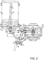
- Figs. 1-3 there is shown the apparatus 10 for loading rolls of web 1 , such as photographic paper, from a stack 3 into a chamber 4 of package 2 , such as the package described in US-A-5,383,591, in accordance with the principals of the invention.
- the objects or rolls 1 having a central opening 5 are arranged in a vertical stack 3 having a first axis 7 near the apparatus 10 .
- the stack 3 typically includes several rolls of web 1 with one roll of web 1 atop the other but, it may include only one roll of web 1 .
- the chamber 4 into which the roll of photographic web 1 is loaded along a spindle 6 defining a second axis 8 transverse to the first axis 7 nominally has a openable end member (not shown) through which the rolls of photographic web 1 enter the chamber 4.
- the spindle 6 set inside the chamber 4 and accessible through the openable end member provides support for the rolls of photographic web 1 that are loaded therein.
- the apparatus 10 of the invention comprises a pivotable support member 12 to which is mounted a means 16 for securely engaging the core of a roll 1 , as further described below.
- support member 12 is pivotably connected to a fixed frame member 14 attached to the floor or some other suitable stable surface.
- the frame member 14 provides a reference axis about which the support member 12 pivots between the first axis 7 of the stack 3 of rolls and the second axis 8 of the chamber 4 .
- Support member 12 is configured to pivot from a first position in alignment with the stack of rolls along the first axis 7 , to a second position in alignment with the chamber 4 along the second axis 8 .
- a pneumatic lift mechanism 19 is provided for raising the head support member 50 , which operates the head member 18 to clear the stack 3 after engaging a roll of web 1 .
- a typical lift mechanism preferred by the inventors is one manufactured by D. W. Zimmerman Handling Systems, Madison Heights, Michigan. Those skilled in the art will appreciate that the head support member 50 may also be raised by other means, such as by an electrically operated hoist.
- the pneumatic lift mechanism 19 is used to raise and lower the head support member 50 , with and without a roll of web 1 on the head member 18 .
- the head support member 50 provides a means to support, and connect, the head member 18 to the support member 12 .
- the engaging means 16 comprises a rotatable extending head member 18 and at least two retractable gripping members 20 mounted in a periphery wall 23 of the head member 18 for engaging the interior wall 9 of the central opening 5 of at least one roll 1 in the stack 3 .
- Preferably four spaced retractable gripping members 20 are positioned about the head member 18 for securely gripping and delivering the roll of web 1 into the chamber 4 .
- a core engaging device preferred by the inventors is one manufactured by Tilt-Lock, Inc. of Columbia Hts., Mn.
- the extending head member 18 is inserted into the central opening 5 of the roll 1 and the retractable gripping members 20 , when activated, are lodged into the interior wall 9 , thereby gripping the central opening 9 and, therefore, the roll 1 in a secure manner.
- Retractable gripping members 20 or “teeth” operate by both gravity and bias springs 51 .
- a light spring pressure is applied to the gripping members 20 that engages them into the interior wall 9 .
- the gripping members 20 penetrate deeper into the interior wall 9 thereby providing secured attachment to the central opening 5 of the roll 1 .
- the head member 18 is preferably substantially cylindrical and has a diameter slightly less than the diameter of the central opening 5 so as to facilitate engagement and securement of the roll 1 .
- Rotation of the head member 18 is achieved by a gear box 21 .
- a gear box 21 preferably one manufactured by DynaTorque Corp. of Muskegon, Mich., is used to rotate the roll web 1 away from the first axis 7 of the vertical stack 3 to a horizontal position, so that it can be inserted onto the fixed spindle 6 along the second axis 8 of the chamber 4 .
- This operation of rotating the roll of web 1 from a vertical to horizontal position is preferably performed approximately half way between the first axis 7 of the vertical stack 3 and the second axis 8 of chamber 4 , as shown in Figure 2. It is accomplished by turning the handle 52 attached to the gear box 21 . Those skilled in the art will appreciate that this latter maneuver can also be performed with an electrically driven device.
- engaging means 16 would satisfy the requirements of the present invention including a pneumatic expandable spindle, a cam activated device, and a threaded expandable spindle (none illustrated).
- the apparatus 10 is shown with the support member 12 having a roll of web 1 secured to the head member 18 , in the manner described above, lifted away from the stack 3 along the first axis 7 and pivoting toward and into alignment with the chamber 2 along the second axis 8 .
- the roll 1 is shown being rotated from a horizontal position in the stack 3 to a substantially vertical position as it approaches and aligns with the chamber 4 along the second axis 8 .
- a guide means 22 comprising a guide track 24 positioned so as to provide continuous riding contact for a follower member 26 fixed to the head support member 50 enables the engaging means 16 to travel between a first elevational position 30 above the stack 3 , to a second elevational position 32 in alignment with the chamber opening.
- frame member 14 is shown having first, second and third stopping means 30,53,44 for support member 12 as it pivots between the stack along the first axis 7 and into the chamber 4 along the second axis 8 .
- First stopping means 30 limits the elevation of the support member 12 when the head member 18 is in alignment with the first axis 7 of the stack 3 .
- Stopping means 53 fixes the centering position of the head member 18 relative to the central openings 5 of the rolls 1 in stack 3 .
- Third stopping means 44 provides a means for precisely and repeatedly positioning the support member 12 when the head member 18 is in alignment with the second axis 8 of the chamber 4 .
- the head member 18 and gear box 21 are mounted on a slide 54 .
- This slide 54 allows the operator to accurately position the head member 18 into the central opening 5 of the roll 1 of web 1 in the stack 3 and "lock" its pick-up position at the stack 3 by means of a clamp 55 on a pneumatic cylinder (not shown).
- the slide 54 also allows the head member 18 to be automatically positioned, by the pneumatic cylinder, at the chamber 4 for loading the roll of web 1 onto the spindle 6 in the chamber 4 .
- a preferred cylinder is one manufactured by Chicago Cylinder Corp. of Chicago, Ill. This feature compensates for any misalignment of the rolls of web 1 in the stack 3 caused in shipping of the stack 3 to the photofinisher, or its placement in the apparatus 10 .
- a method for loading a roll of web 1 from a stack 3 into a chamber 4 having a spindle 6 for receiving the roll 1 comprising the step of providing apparatus 10 , as described above, having a rotatable extending head member 18 for engaging a roll of web 1 .
- the head member 18 is centered along the first axis 7 with the central opening 5 of the top most roll 1 in the stack 3 . After centering the head member 18 , it is lowered into the central opening 5 of the top most roll 1 in the stack 3 .
- An engaging means 16 is then activated that securely engages the interior wall 9 of the central opening 5 of roll 1 thereby locking the roll 1 onto the head member 18 .
- the head member 18 with a roll of web 1 locked thereon is raised first upwardly along the first axis 7 away from the stack 3 with the aid of lift mechanism 19 .
- the head member 18 with the roll 1 locked thereon is then guided into alignment with the chamber 4 along the second axis 8 .
- the roll 1 is then inserted therein by first releasing the roll of web 1 from the head member 18 and then pushing the roll 1 into sliding contact with the spindle 6 inside the chamber 4 .
- the head member 18 is moved away along the second axis 9 of the chamber 4 and then back into position to engage another roll 1 in the stack 3 along the first axis 7 .
- an important advantage of the present invention is that it provides an apparatus 10 and method for loading rolls of photographic web 1 into a chamber 4 that is convenient to use, of simple construction, economical and easy to manufacture, compact and easily operated by the photofinisher.
Landscapes
- Physics & Mathematics (AREA)
- General Physics & Mathematics (AREA)
- Replacement Of Web Rolls (AREA)
- Unwinding Webs (AREA)
- De-Stacking Of Articles (AREA)
Claims (5)
- Appareil (10) destiné à charger un objet (1) comprenant une ouverture centrale (5) définie par une paroi intérieure (9), comprenant un élément de bâti fixe (14) présentant un axe de référence, une pile (3) contenant ledit objet (1) qui est espacée dudit bâti (14), ladite pile présentant un premier axe (7), ledit appareil (10) étant caractérisé par :une chambre (4) agencée par rapport au bâti (14) afin de recevoir ledit objet (1), ladite chambre présentant un second axe (8) transversal audit premier axe (7) de ladite pile (3),un élément de support (12) monté de façon pivotante sur ledit élément de bâti (14) afin de tourner autour dudit axe de référence entre une première position en élévation au-dessus de la pile (3) et une seconde position en élévation en alignement avec l'ouverture de la chambre (4),un élément de support de tête (50) monté sur ledit élément de support (12), ledit élément de support de tête (50) comportant un élément de tête (18) monté sur celui-ci,un moyen destiné à guider (22) ledit élément de support de tête (50), ledit moyen destiné à guider (22) comprenant une piste de guidage (24), ladite piste de guidage (24) définissant une première position en élévation suivant ledit premier axe (7) et une seconde position en élévation suivant ledit second axe (8),un moyen de saisie (16) monté avec possibilité de rotation sur ledit élément de tête (18) afin de saisir fermement l'objet (1) suivant ledit premier axe (7) et de délivrer l'objet (1) suivant ledit second axe (8) dans la chambre (4), etun moyen (19) monté sur ledit élément de support (12) afin d'élever et d'abaisser ledit élément de tête (18) entre lesdites première et seconde positions.
- Appareil (10) selon la revendication 1, caractérisé en outre par un premier moyen d'arrêt (30) destiné à limiter l'élévation de l'élément de support (12) lorsque l'élément de tête (18) est en alignement avec le premier axe (7) de la pile (3).
- Appareil (10) selon la revendication 2, caractérisé en outre par un second moyen d'arrêt (53) destiné à positionner de façon précise et répétitive ledit élément de tête (18) par rapport à ladite ouverture centrale (5) dudit objet (1).
- Appareil (10) selon la revendication 3, caractérisé en outre par un troisième moyen d'arrêt (44) destiné à positionner de façon précise et répétitive ledit élément de support (12) lorsque l'élément de tête (18) est en alignement avec ledit second axe (8) de la chambre (4).
- Appareil (10) selon la revendication 1, caractérisé en outre par une coulisse (54) montée sur ledit élément de support de tête (5), ledit moyen de saisie (16) étant supporté par ladite coulisse (54).
Applications Claiming Priority (2)
| Application Number | Priority Date | Filing Date | Title |
|---|---|---|---|
| US139377 | 1987-12-30 | ||
| US08/139,377 US5487638A (en) | 1993-10-20 | 1993-10-20 | Apparatus and method for loading rolls of web into a chamber |
Publications (2)
| Publication Number | Publication Date |
|---|---|
| EP0649806A1 EP0649806A1 (fr) | 1995-04-26 |
| EP0649806B1 true EP0649806B1 (fr) | 1998-09-23 |
Family
ID=22486337
Family Applications (1)
| Application Number | Title | Priority Date | Filing Date |
|---|---|---|---|
| EP94116038A Expired - Lifetime EP0649806B1 (fr) | 1993-10-20 | 1994-10-12 | Appareil et procédé pour charger des rouleaux de bande dans un récipient |
Country Status (6)
| Country | Link |
|---|---|
| US (1) | US5487638A (fr) |
| EP (1) | EP0649806B1 (fr) |
| JP (1) | JP2558229B2 (fr) |
| AU (1) | AU680535B2 (fr) |
| CA (1) | CA2117724A1 (fr) |
| DE (1) | DE69413490T2 (fr) |
Cited By (1)
| Publication number | Priority date | Publication date | Assignee | Title |
|---|---|---|---|---|
| CN103018036A (zh) * | 2012-11-23 | 2013-04-03 | 浙江美科斯叉车有限公司 | 变速箱检测装置 |
Families Citing this family (36)
| Publication number | Priority date | Publication date | Assignee | Title |
|---|---|---|---|---|
| US5913655A (en) * | 1996-01-17 | 1999-06-22 | Industrial Innovations, Inc. | Automatic depalletizing system and method |
| AU2222597A (en) * | 1996-02-27 | 1997-09-16 | John Campbell | Transporting apparatus |
| IT1299847B1 (it) * | 1998-02-17 | 2000-04-04 | Gd Spa | Metodo e dispositivo per l'alimentazione di bobine. |
| DE19806432A1 (de) * | 1998-02-17 | 1999-08-19 | Focke & Co | Vorrichtung zum Handhaben von Bobinen |
| DE19851898A1 (de) * | 1998-11-11 | 2000-06-15 | Rieter Ag Maschf | Drehstation für Wickel |
| US6264417B1 (en) * | 1999-04-21 | 2001-07-24 | Eastman Kodak Company | Flexible roll chucking assemblage and method |
| DE19961926A1 (de) | 1999-12-22 | 2001-07-05 | Basf Coatings Ag | Thermisch mit aktinischer Strahlung härtbare Stoffgemische und ihre Verwendung |
| DE10041634C2 (de) | 2000-08-24 | 2002-10-17 | Basf Coatings Ag | Wäßrige Dispersion und ihre Verwendung zur Herstellung von thermisch und mit aktinischer Strahlung härtbaren Beschichtungsstoffen, Klebstoffen und Dichtungsmassen |
| US6508617B1 (en) * | 2000-11-09 | 2003-01-21 | Abb Technology Ag | Device for lifting, orienting, and positioning enclosures |
| DE60227742D1 (de) * | 2001-05-11 | 2008-09-04 | Gd Spa | Verfahren und Vorrichtung zum Zuführen von Verpackungsmaterial zu einer Verarbeitungseinheit |
| ITBO20010289A1 (it) * | 2001-05-11 | 2002-11-11 | Gd Spa | Metodo e dispositivo di alimentazione di bobine ad una macchina operatrice |
| DE10139262C1 (de) | 2001-08-09 | 2003-01-02 | Basf Coatings Ag | Rheologiehilfsmittel, Verfahren zu seiner Herstellung und seine Verwendung |
| DE10162179A1 (de) * | 2001-12-18 | 2003-07-10 | G & L Heikaus Kunststoffverarb | Bereitstellungsvorrichtung für Folienrollenkerne und Verfahren zum Bereitstellen von Folienrollenkernen |
| US20040189030A1 (en) * | 2003-03-31 | 2004-09-30 | Briggs William J. | Adjustable roll handling hoist |
| DE102005045150A1 (de) | 2005-09-22 | 2007-04-05 | Basf Coatings Ag | Verwendung von Phosphonsäurediestern und Diphosphonsäurediestern sowie thermisch härtbare Gemische, enthaltend Phosphonsäurediester und Diphosphonsäurediester |
| DE102005045228A1 (de) | 2005-09-22 | 2007-04-05 | Basf Coatings Ag | Verwendung von Phosphonsäurediestern und Diphosphonsäurediestern sowie silangruppenhaltige, härtbare Gemische, enthaltend Phosphonsäurediester und Diphosphonsäurediester |
| DE102005053661A1 (de) | 2005-11-10 | 2007-05-16 | Basf Coatings Ag | Reparaturfolien und ihre Verwendung |
| DE102005060638A1 (de) * | 2005-12-13 | 2007-06-14 | Hauni Maschinenbau Ag | Vorrichtung und Verfahren zum Handhaben von Bobinen innerhalb einer Automatisierungszelle sowie Automatisierungszelle |
| US20070231577A1 (en) * | 2006-03-30 | 2007-10-04 | Basf Corporation | Coatings for polycarbonate windows |
| DE102006017379A1 (de) * | 2006-04-11 | 2007-10-18 | Focke & Co.(Gmbh & Co. Kg) | Einrichtung zur Handhabung von Bobinen aus Verpackungsmaterial |
| DE102006024823A1 (de) | 2006-05-29 | 2007-12-06 | Basf Coatings Ag | Verwendung von härtbaren Gemischen, enthaltend silangruppenhaltige Verbindungen sowie Phosphonsäurediester oder Diphosphonsäurediester, als Haftvermittler |
| DE102007014720A1 (de) | 2007-03-23 | 2008-09-25 | Basf Coatings Japan Ltd., Yokohama | Phosphonat-haltiges Zweikomponenten-Lacksystem, dessen Herstellung und Verwendung |
| US7785061B2 (en) * | 2007-12-21 | 2010-08-31 | The Goodyear Tire & Rubber Company | Apparatus and method for reorienting a tire and core assembly in a tire manufacturing line |
| ITBO20120709A1 (it) * | 2012-12-27 | 2014-06-28 | Sorma S P A | Dispositivo per il cambio di bobine di materiale da imballaggio per macchine confezionatrici |
| CN103350907B (zh) * | 2013-08-01 | 2015-09-30 | 广州中国科学院沈阳自动化研究所分所 | 一种用于小瓷砖包装的堆叠机及控制方法 |
| CN103418737B (zh) * | 2013-08-30 | 2016-01-20 | 太原重工股份有限公司 | 一种电极压机的堆垛装置 |
| DE102013110944A1 (de) * | 2013-10-02 | 2015-04-02 | Krones Aktiengesellschaft | Verfahren und Vorrichtung zum Wechseln von Trägereinheiten mit auf Vorratsrollen aufgewickeltem flächigem Verpackungsmaterial innerhalb einer Verpackungsmaschine |
| US9969587B2 (en) | 2014-08-28 | 2018-05-15 | The Procter & Gamble Company | Web material unwind apparatus |
| US9919887B2 (en) * | 2014-08-28 | 2018-03-20 | The Procter & Gamble Company | Web material unwind stand |
| CN107548376B (zh) * | 2015-04-30 | 2020-08-07 | 克朗斯股份公司 | 用于输送、提供和更换带有卷绕在其上的扁平和/或薄膜材料的卷筒的方法和设备 |
| CN105347054B (zh) * | 2015-12-01 | 2017-10-17 | 河南小大机器人股份公司 | 集装箱气动式快速码垛机 |
| DE102019201595A1 (de) * | 2019-02-07 | 2020-08-13 | Bhs Intralogistics Gmbh | Übergabesystem |
| CN111891774A (zh) * | 2020-08-06 | 2020-11-06 | 习锦林 | 一种智能制造车间自动码垛上车装置 |
| IT202000030644A1 (it) * | 2020-12-14 | 2022-06-14 | Futura Spa | Dispositivo e metodo per la manipolazione di bobine di cartone. |
| IT202000030662A1 (it) * | 2020-12-14 | 2022-06-14 | Futura Spa | Impianto e processo per la movimentazione di bobine di cartone. |
| US20240314993A1 (en) * | 2021-07-14 | 2024-09-19 | Fuji Corporation | Feeder setup device and feeder setup system |
Family Cites Families (10)
| Publication number | Priority date | Publication date | Assignee | Title |
|---|---|---|---|---|
| US2551011A (en) * | 1948-01-05 | 1951-05-01 | Liquid Carbonic Corp | Spinner brake for beverage mixers |
| LU67379A1 (fr) * | 1973-04-06 | 1973-06-18 | ||
| DE2710661C2 (de) * | 1977-03-11 | 1984-04-12 | Index-Werke Kg Hahn & Tessky, 7300 Esslingen | Einrichtung zum Transport eines Werkstückes zwischen einem Werkstückspeicher und einer Werkzeugmaschine |
| IT1145030B (it) * | 1981-02-25 | 1986-11-05 | Gd Spa | Dispositivo per l'alimentazione automatica di bobine ad una macchina operatrice |
| US4708574A (en) * | 1985-07-05 | 1987-11-24 | D. W. Zimmerman Mfg., Inc. | Apparatus for handling objects |
| US4687244A (en) * | 1985-09-20 | 1987-08-18 | Tilt-Lock, Inc. | Lift and reorienting mechanism |
| JPS62251125A (ja) * | 1986-04-25 | 1987-10-31 | Bridgestone Corp | 成型・加硫工程間の生タイヤ自動搬送設備 |
| JPS63306149A (ja) * | 1987-05-30 | 1988-12-14 | Yoshida Kogyo Kk <Ykk> | スプ−ル排出方法およびその排出装置 |
| US4941798A (en) * | 1987-10-13 | 1990-07-17 | Sft Ag Spontanfordertechnik | Means for manipulating and transporting loads |
| IT1242891B (it) * | 1990-12-24 | 1994-05-18 | Gd Spa | Metodo e dispositivo per il cambio di bobine in una macchina utilizzatrice di materiale in nastro. |
-
1993
- 1993-10-20 US US08/139,377 patent/US5487638A/en not_active Expired - Fee Related
-
1994
- 1994-09-30 AU AU74357/94A patent/AU680535B2/en not_active Ceased
- 1994-10-06 JP JP6243075A patent/JP2558229B2/ja not_active Expired - Lifetime
- 1994-10-07 CA CA002117724A patent/CA2117724A1/fr not_active Abandoned
- 1994-10-12 EP EP94116038A patent/EP0649806B1/fr not_active Expired - Lifetime
- 1994-10-12 DE DE69413490T patent/DE69413490T2/de not_active Expired - Fee Related
Non-Patent Citations (1)
| Title |
|---|
| TVER D.F. AND BOLZ R.W.: "Robotics Sourcebook and dictionary", 1983, INDUSTRIAL PRESS, NEW YORK * |
Cited By (2)
| Publication number | Priority date | Publication date | Assignee | Title |
|---|---|---|---|---|
| CN103018036A (zh) * | 2012-11-23 | 2013-04-03 | 浙江美科斯叉车有限公司 | 变速箱检测装置 |
| CN103018036B (zh) * | 2012-11-23 | 2015-06-17 | 浙江美科斯叉车有限公司 | 变速箱检测装置 |
Also Published As
| Publication number | Publication date |
|---|---|
| JPH07206159A (ja) | 1995-08-08 |
| AU680535B2 (en) | 1997-07-31 |
| AU7435794A (en) | 1995-05-11 |
| US5487638A (en) | 1996-01-30 |
| EP0649806A1 (fr) | 1995-04-26 |
| JP2558229B2 (ja) | 1996-11-27 |
| DE69413490D1 (de) | 1998-10-29 |
| DE69413490T2 (de) | 1999-05-27 |
| CA2117724A1 (fr) | 1995-04-21 |
Similar Documents
| Publication | Publication Date | Title |
|---|---|---|
| EP0649806B1 (fr) | Appareil et procédé pour charger des rouleaux de bande dans un récipient | |
| EP0407162B1 (fr) | Voiture destinée au transport d'un objet cylindrique | |
| JP2522535B2 (ja) | ロ―ル支持・供給装置 | |
| EP0244059A2 (fr) | Appareil pour transférer des tambours vers la bobineuse d'une machine de fabrication de papier ou de carton | |
| JPH021056B2 (fr) | ||
| JPH07232844A (ja) | 利用機器へのリール供給装置 | |
| US6533212B1 (en) | Web-splicing apparatus | |
| JPS62221541A (ja) | 自動刷版装着装置 | |
| US4339093A (en) | Pneumatic roll lifter | |
| US4537368A (en) | Pendulum roll loader | |
| US20040011914A1 (en) | Charging and discharging device for material in the form of a roll and a combination of a printing device and a charging an discharging device | |
| US20020197143A1 (en) | Coil handling device | |
| US5433576A (en) | Low profile dolly and ramp assembly for a roll | |
| GB2269806A (en) | Lifting device | |
| US5187520A (en) | Photographic copying apparatus | |
| CA1088487A (fr) | Bobine de transport de fil avec appareil de soutien et de levage | |
| JPH0777751A (ja) | 自動ローダのカセット移送装置 | |
| EP0646833B1 (fr) | Emballage pour bobines de bande photosensible | |
| US20050145744A1 (en) | Automatic reel changer comprising a reel stand and a method for disposing of residual reel casings | |
| JPH0270645A (ja) | オートリールローダ | |
| JP3194023B2 (ja) | ガス容器用パレットの起伏装置 | |
| KR0124980B1 (ko) | 트레일러 | |
| JPH0536803Y2 (fr) | ||
| JPH0344771Y2 (fr) | ||
| JPH0524655A (ja) | コンテナ受台 |
Legal Events
| Date | Code | Title | Description |
|---|---|---|---|
| PUAI | Public reference made under article 153(3) epc to a published international application that has entered the european phase |
Free format text: ORIGINAL CODE: 0009012 |
|
| AK | Designated contracting states |
Kind code of ref document: A1 Designated state(s): DE FR GB NL |
|
| 17P | Request for examination filed |
Effective date: 19950928 |
|
| 17Q | First examination report despatched |
Effective date: 19960625 |
|
| GRAG | Despatch of communication of intention to grant |
Free format text: ORIGINAL CODE: EPIDOS AGRA |
|
| GRAG | Despatch of communication of intention to grant |
Free format text: ORIGINAL CODE: EPIDOS AGRA |
|
| GRAG | Despatch of communication of intention to grant |
Free format text: ORIGINAL CODE: EPIDOS AGRA |
|
| GRAH | Despatch of communication of intention to grant a patent |
Free format text: ORIGINAL CODE: EPIDOS IGRA |
|
| GRAH | Despatch of communication of intention to grant a patent |
Free format text: ORIGINAL CODE: EPIDOS IGRA |
|
| GRAA | (expected) grant |
Free format text: ORIGINAL CODE: 0009210 |
|
| AK | Designated contracting states |
Kind code of ref document: B1 Designated state(s): DE FR GB NL |
|
| PGFP | Annual fee paid to national office [announced via postgrant information from national office to epo] |
Ref country code: GB Payment date: 19981001 Year of fee payment: 5 |
|
| PGFP | Annual fee paid to national office [announced via postgrant information from national office to epo] |
Ref country code: FR Payment date: 19981006 Year of fee payment: 5 |
|
| PGFP | Annual fee paid to national office [announced via postgrant information from national office to epo] |
Ref country code: NL Payment date: 19981028 Year of fee payment: 5 Ref country code: DE Payment date: 19981028 Year of fee payment: 5 |
|
| REF | Corresponds to: |
Ref document number: 69413490 Country of ref document: DE Date of ref document: 19981029 |
|
| ET | Fr: translation filed | ||
| PLBE | No opposition filed within time limit |
Free format text: ORIGINAL CODE: 0009261 |
|
| STAA | Information on the status of an ep patent application or granted ep patent |
Free format text: STATUS: NO OPPOSITION FILED WITHIN TIME LIMIT |
|
| 26N | No opposition filed | ||
| PG25 | Lapsed in a contracting state [announced via postgrant information from national office to epo] |
Ref country code: GB Free format text: LAPSE BECAUSE OF NON-PAYMENT OF DUE FEES Effective date: 19991012 |
|
| PG25 | Lapsed in a contracting state [announced via postgrant information from national office to epo] |
Ref country code: NL Free format text: LAPSE BECAUSE OF NON-PAYMENT OF DUE FEES Effective date: 20000501 |
|
| GBPC | Gb: european patent ceased through non-payment of renewal fee |
Effective date: 19991012 |
|
| PG25 | Lapsed in a contracting state [announced via postgrant information from national office to epo] |
Ref country code: FR Free format text: LAPSE BECAUSE OF NON-PAYMENT OF DUE FEES Effective date: 20000630 |
|
| NLV4 | Nl: lapsed or anulled due to non-payment of the annual fee |
Effective date: 20000501 |
|
| PG25 | Lapsed in a contracting state [announced via postgrant information from national office to epo] |
Ref country code: DE Free format text: LAPSE BECAUSE OF NON-PAYMENT OF DUE FEES Effective date: 20000801 |
|
| REG | Reference to a national code |
Ref country code: FR Ref legal event code: ST |