EP0651141A1 - Moteur à combustion interne à quatretemps - Google Patents
Moteur à combustion interne à quatretemps Download PDFInfo
- Publication number
- EP0651141A1 EP0651141A1 EP94117108A EP94117108A EP0651141A1 EP 0651141 A1 EP0651141 A1 EP 0651141A1 EP 94117108 A EP94117108 A EP 94117108A EP 94117108 A EP94117108 A EP 94117108A EP 0651141 A1 EP0651141 A1 EP 0651141A1
- Authority
- EP
- European Patent Office
- Prior art keywords
- cycle engine
- engine
- cylinder block
- water pump
- chain
- Prior art date
- Legal status (The legal status is an assumption and is not a legal conclusion. Google has not performed a legal analysis and makes no representation as to the accuracy of the status listed.)
- Granted
Links
- XLYOFNOQVPJJNP-UHFFFAOYSA-N water Substances O XLYOFNOQVPJJNP-UHFFFAOYSA-N 0.000 claims abstract description 63
- 238000001816 cooling Methods 0.000 claims abstract description 13
- 239000000498 cooling water Substances 0.000 claims description 15
- 230000000063 preceeding effect Effects 0.000 claims 14
- 239000002826 coolant Substances 0.000 description 28
- 238000012423 maintenance Methods 0.000 description 2
- 238000009877 rendering Methods 0.000 description 2
- 230000004308 accommodation Effects 0.000 description 1
- 238000004378 air conditioning Methods 0.000 description 1
- 230000005540 biological transmission Effects 0.000 description 1
- 238000010586 diagram Methods 0.000 description 1
- 230000002093 peripheral effect Effects 0.000 description 1
- 238000003825 pressing Methods 0.000 description 1
Images


Classifications
-
- F—MECHANICAL ENGINEERING; LIGHTING; HEATING; WEAPONS; BLASTING
- F01—MACHINES OR ENGINES IN GENERAL; ENGINE PLANTS IN GENERAL; STEAM ENGINES
- F01P—COOLING OF MACHINES OR ENGINES IN GENERAL; COOLING OF INTERNAL-COMBUSTION ENGINES
- F01P5/00—Pumping cooling-air or liquid coolants
- F01P5/10—Pumping liquid coolant; Arrangements of coolant pumps
-
- F—MECHANICAL ENGINEERING; LIGHTING; HEATING; WEAPONS; BLASTING
- F01—MACHINES OR ENGINES IN GENERAL; ENGINE PLANTS IN GENERAL; STEAM ENGINES
- F01P—COOLING OF MACHINES OR ENGINES IN GENERAL; COOLING OF INTERNAL-COMBUSTION ENGINES
- F01P11/00—Component parts, details, or accessories not provided for in, or of interest apart from, groups F01P1/00 - F01P9/00
- F01P11/04—Arrangements of liquid pipes or hoses
-
- F—MECHANICAL ENGINEERING; LIGHTING; HEATING; WEAPONS; BLASTING
- F02—COMBUSTION ENGINES; HOT-GAS OR COMBUSTION-PRODUCT ENGINE PLANTS
- F02B—INTERNAL-COMBUSTION PISTON ENGINES; COMBUSTION ENGINES IN GENERAL
- F02B67/00—Engines characterised by the arrangement of auxiliary apparatus not being otherwise provided for, e.g. the apparatus having different functions; Driving auxiliary apparatus from engines, not otherwise provided for
- F02B67/04—Engines characterised by the arrangement of auxiliary apparatus not being otherwise provided for, e.g. the apparatus having different functions; Driving auxiliary apparatus from engines, not otherwise provided for of mechanically-driven auxiliary apparatus
- F02B67/06—Engines characterised by the arrangement of auxiliary apparatus not being otherwise provided for, e.g. the apparatus having different functions; Driving auxiliary apparatus from engines, not otherwise provided for of mechanically-driven auxiliary apparatus driven by means of chains, belts, or like endless members
-
- F—MECHANICAL ENGINEERING; LIGHTING; HEATING; WEAPONS; BLASTING
- F01—MACHINES OR ENGINES IN GENERAL; ENGINE PLANTS IN GENERAL; STEAM ENGINES
- F01M—LUBRICATING OF MACHINES OR ENGINES IN GENERAL; LUBRICATING INTERNAL COMBUSTION ENGINES; CRANKCASE VENTILATING
- F01M11/00—Component parts, details or accessories, not provided for in, or of interest apart from, groups F01M1/00 - F01M9/00
- F01M11/02—Arrangements of lubricant conduits
-
- F—MECHANICAL ENGINEERING; LIGHTING; HEATING; WEAPONS; BLASTING
- F01—MACHINES OR ENGINES IN GENERAL; ENGINE PLANTS IN GENERAL; STEAM ENGINES
- F01M—LUBRICATING OF MACHINES OR ENGINES IN GENERAL; LUBRICATING INTERNAL COMBUSTION ENGINES; CRANKCASE VENTILATING
- F01M11/00—Component parts, details or accessories, not provided for in, or of interest apart from, groups F01M1/00 - F01M9/00
- F01M11/03—Mounting or connecting of lubricant purifying means relative to the machine or engine; Details of lubricant purifying means
-
- F—MECHANICAL ENGINEERING; LIGHTING; HEATING; WEAPONS; BLASTING
- F01—MACHINES OR ENGINES IN GENERAL; ENGINE PLANTS IN GENERAL; STEAM ENGINES
- F01M—LUBRICATING OF MACHINES OR ENGINES IN GENERAL; LUBRICATING INTERNAL COMBUSTION ENGINES; CRANKCASE VENTILATING
- F01M1/00—Pressure lubrication
- F01M1/10—Lubricating systems characterised by the provision therein of lubricant venting or purifying means, e.g. of filters
- F01M2001/1007—Lubricating systems characterised by the provision therein of lubricant venting or purifying means, e.g. of filters characterised by the purification means combined with other functions
- F01M2001/1014—Lubricating systems characterised by the provision therein of lubricant venting or purifying means, e.g. of filters characterised by the purification means combined with other functions comprising supply of additives
-
- F—MECHANICAL ENGINEERING; LIGHTING; HEATING; WEAPONS; BLASTING
- F01—MACHINES OR ENGINES IN GENERAL; ENGINE PLANTS IN GENERAL; STEAM ENGINES
- F01M—LUBRICATING OF MACHINES OR ENGINES IN GENERAL; LUBRICATING INTERNAL COMBUSTION ENGINES; CRANKCASE VENTILATING
- F01M5/00—Heating, cooling, or controlling temperature of lubricant; Lubrication means facilitating engine starting
- F01M5/002—Cooling
-
- F—MECHANICAL ENGINEERING; LIGHTING; HEATING; WEAPONS; BLASTING
- F01—MACHINES OR ENGINES IN GENERAL; ENGINE PLANTS IN GENERAL; STEAM ENGINES
- F01P—COOLING OF MACHINES OR ENGINES IN GENERAL; COOLING OF INTERNAL-COMBUSTION ENGINES
- F01P2060/00—Cooling circuits using auxiliaries
- F01P2060/04—Lubricant cooler
-
- F—MECHANICAL ENGINEERING; LIGHTING; HEATING; WEAPONS; BLASTING
- F02—COMBUSTION ENGINES; HOT-GAS OR COMBUSTION-PRODUCT ENGINE PLANTS
- F02B—INTERNAL-COMBUSTION PISTON ENGINES; COMBUSTION ENGINES IN GENERAL
- F02B75/00—Other engines
- F02B75/02—Engines characterised by their cycles, e.g. six-stroke
- F02B2075/022—Engines characterised by their cycles, e.g. six-stroke having less than six strokes per cycle
- F02B2075/027—Engines characterised by their cycles, e.g. six-stroke having less than six strokes per cycle four
-
- F—MECHANICAL ENGINEERING; LIGHTING; HEATING; WEAPONS; BLASTING
- F02—COMBUSTION ENGINES; HOT-GAS OR COMBUSTION-PRODUCT ENGINE PLANTS
- F02B—INTERNAL-COMBUSTION PISTON ENGINES; COMBUSTION ENGINES IN GENERAL
- F02B2275/00—Other engines, components or details, not provided for in other groups of this subclass
- F02B2275/06—Endless member is a belt
Definitions
- the present invention relates to a four-cycle engine comprising a cylinder block and a cylinder head, a chain drive means for driving at least one camshaft from the primary drive shaft, a chain cover extending along a side of the engine and a cooling arrangement including a water pump for circulating cooling water through the engine.
- a water jacket surrounds the outside of the cylinders, and coolant from the radiator is circulated through this jacket to cool the engine.
- a water pump and its drive propel this coolant, which has become heated after cooling the engine, back to the radiator, where it is cooled, and then, to return the coolant to the water jacket.
- the water-pump impeller-housing is mounted on the cylinder block so that said impeller housing connects to a coolant passage linking it with the opening of the water jacket, and a pulley on the rotating shaft of the impeller is driven by belt from a crankshaft pulley. Part of the coolant supplied by the water pump is circulated to the oil cooler.
- the four-cycle engine comprises a chain cover which simultaneously defines at least partially a housing for the water pump.
- the water pump of the cooling arrangement circulating the cooling water through the cylinder block and cylinder head of the engine being integrated into a chain cover area itself, which improves the layout and compactness of the engine.
- another closure means or cover is provided to cover the water pump and to connect to the chain cover.
- the water pump even though the water pump is disposed to the engine at the side along the width of the engine where same is covered by the chain cover of the timer chains of the camshaft drive system, the water pump does not protrude from the surface of said chain cover and is integrated into that side of the engine, thereby, among others, rendering it possible to drive the driving pulley fixed to the pump shaft of the water pump with the belt that additionally drives other accessory equipment from a crankshaft pulley.
- this arrangement also allows the water pump as well as the other peripherals in the area of the engine to be driven using a single drive belt, which renders the driving system more efficient.
- the present invention allows the water pump to be located in close proximity to an opening for the water jacket in the cylinder block, so that water can be very efficiently supplied from the water pump housing to the water jacket inside the cylinder block.
- a coolant passage can be formed in the water pump housing which is also formed to be an integral part of the engine to supply coolant to an oil cooler, thus eliminating the need for extra parts such as hoses in order to circulate the cooling water to more remote parts of the engine to be cooled.
- the present invention is useful for a high performance five-valve engine having three intake valves and two exhaust valves per cylinder.
- Embodiments of the cooling structure of this invention will be described below as a part of the multi-cylinder four-cycle engine shown in the attached figures.
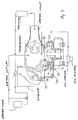
- Figure 1 shows the location of the auxiliary equipment positioned around the engine, which is a multi-cylinder four-cycle engine, viewed along the line of cylinders.
- the alternator 2 Located around the engine 1 are the alternator 2, the power steering pump 3, the air conditioning compressor 4, etc.
- These pieces of auxiliary equipment are driven at their respective rotating shafts 21, 31, 41 by a single belt 7 which connects the various pulleys 12, 22, 32, 42, 52 to that of the engine crankshaft 11.
- An oil cooler 8 equipped with a filter unit is mounted at the bottom of the engine 1.
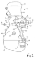
- FIG 2 shows the engine 1 of Figure 1.
- the engine 1 is covered by head cover 13, mounted over the cylinder head 14; on the side, a chain cover 16 covers the cylinder block 15 (which, in this embodiment, consists of a cylinder block unit and a crankcase) and on the bottom, an oil pan 17 is mounted under the cylinder block 15.
- a water pump 5 is affixed to the surface of chain cover 16.
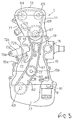
- FIG 3 shows the engine 1 of Figure 2 with the chain cover 16 removed.
- An inlet 18 is present on the upper part of the side of the cylinder block 15 where the water pump 5 introduces the coolant, and an inlet 19 is located nearby through which coolant is introduced into the water jacket, and below is an oil passage 83 through which oil is introduced into the oil cooler 8.
- Sprockets 60 are affixed parallel to each other on the crankshaft 11, and chains 61, 62 engage the teeth on these sprockets, respectively.
- Said side of the cylinder block 15 where the timer chain transmission for driving the camshafts 64,65 and the other auxiliary equipment and the water pump 5 is positioned is disposed closer to an adjacent cylinder of the cylinder block 15 than the opposite end side of the cylinder block 15 (said side also extending inthe widthwise direction, not shown in the drawings).
- a lower chain 61 transmits the drive from the rotation of crankshaft 11 to the air intake camshaft 64 and to the exhaust camshaft 65 by means of an intermediate rotating shaft 67 and an upper chain 68 at the top of the engine, which is a five valve twin cam (not shown) engine with three air intake valves and two exhaust valves per cylinder, causing the camshafts 64, 65 to rotate in this two-stage timing chain configuration.
- the chain 62 located near bottom of the engine transmits the drive of the crankshaft 11 to the rotating shaft 63 of an oil pump (not shown) situated inside the oil pan 17.
- twin chains which rotate the various camshafts 64, 65 of the twin cam valve system can be adjusted externally by means of a tensioner 71 for the upper chain 68 that is mounted on the cylinder head 14, and by a tensioner 72 for the lower chain mounted on the cylinder block 15.
- the tensioner 71 servicing the air intake camshaft 64, the exhaust camshaft 65, and the intermediate rotating shaft 67 is located slightly farther away than usual from the center line passing through crankshaft 11 in order to make room for it to be mounted on the cylinder head 14.
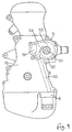
- the adjoining surfaces 15a, 15b between the side of the cylinder block 16 and the chain cover are located in mutually offset and parallel planes of the cross sectional surface.
- the projecting adjoining surface 15a of the cylinder block comprises an integral support area 15c projecting from the cylinder block and supporting a mounting arm 23 of the alternator 2 to allow bolting said alternator at the support 15c to the affixation area 15d.
- a mounting hole 15e passes through the cylinder block 15 below this alternator support area 15c, allowing mounting a cylinder 72c for the push rod 72b applying pressure to the tension arm 72a of the tensioner 72.
- the lower chain tensioner 72 is supported at a portion of the cylinder block 15 which is correspondingly provided at the opposite end side of the cylinder block 15 (said side also extending in the widthwise direction, not shown in the drawings).
- Figure 6 shows the affixation area on engine 1 for the assembly bracket 9 which allows the engine 1 to be affixed to the vehicle frame.
- the mounting bracket 9 is affixed as jaw-like appendage onto both the cylinder head 14 and the cylinder block 15, and there are affixation areas 90a, 90b, 90c, and 90d which correspond to the various affixation areas 10a, 10b, 10c, 10d on the engine 1 to attach the engine 1 to the frame at the affixation area 91.
- the top mounting arm 24 of the alternator 2 bolts onto the affixation area 92.
- the alternator 2 is also supported by the mounting arm 23 below, which is bolted to the affixation area 15d of the alternator support 15c that is integral with the cylinder block, thereby being attached at the top and bottom with respect to engine 1 as shown in Figure 1.
- This arrangement namely the lower mounting arm 23 for the alternator 2 increasing the strength of affixation to the engine, and the upper mounting arm 24 being affixed to the vehicle by the assembly bracket 9 minimizes engine vibrations in that area, thereby allowing the accommodation of any future change in alternator specifications by merely changing the assembly bracket 9 holding such an alternator.
- the housing of the water pump 5 is integral in the chain cover and this housing area is covered by the cover 50, whereby the various coolant passages 54, 55 are made contiguous with the impeller housing 53.
- the impeller 57 is located inside the impeller housing 53; the extension of the shaft 51 of impeller 57 to the outside of the cover 50 allows a pulley 52 to be attached to the end of said shaft and to be be driven by the crankshaft of engine 1 in order to recirculate coolant as shown in Figure 7.
- the coolant passage 54 leading to the opening 19 for the water jacket is considerably shorter than the coolant passage 55 leading to the oil cooler 8, and these coolant passages 54, 55 are formed, respectively, in the cover 50 and in the chain cover 16 so that they are contiguous with the impeller housing 53.
- the coolant passage 55 leading to the oil cooler 8 is formed in the chain cover 16 and in the cover 50, and the cover 50 extends integrally downward from the impeller housing, along the surface of the chain cover, to the vicinity of the oil cooler 8 under the cylinder block 15.
- the coolant passage 55 leading from the water pump 5 to the oil cooler 8 it is not only possible to form the passage in the chain cover 16 and cover 50, but as shown in Figure 8, the coolant passage 55 leading to the oil cooler 8 may equally well be formed integrally on the back side of the chain cover 16. Further, as shown in Figure 9, the coolant passage 55 to the oil cooler 8 may also be formed in the cylinder block 15, integral with the structural components of the engine, thereby eliminating the need for hoses and the like.
- the cross sections of the surfaces 15a, 15b of the cylinder block 15 adjoining the chain cover are in offset and mutual parallel planes. Since the water pump 5 is integral with the side adjoining the surface 15b, compared to the case where the adjoining surface on the cylinder block side lies in the same plane as the surface on the other side, then the water pump 5, even though covered by the chain cover 16, does not project as far from the side of the engine 1. And, since it is near the opening 19 leading to the water jacket of the cylinder block 15, the structure allows the water pump 5 to be driven by engine 1 in a very compact manner.
- This configuration allows the water pump 5 to be situated in such manner that the pulley 52 attached to the rotating impeller shaft 51 of the water pump 5 can be efficiently driven by the crankshaft 11, along with the other auxiliary equipment, by means of a single belt 7.
- this configuration simplifies the structures and improves the ease of maintenance by eliminating the need for extra parts such as hoses to provide the coolant passage to the oil cooler.
- the cooling structure for four-cycle engines of this invention uses the chain cover that covers the side of the engine as a part of the water pump so that the water pump does not substantially project from the surface of the chain cover, and as a result the water pump may be located in close proximity to the opening for the water jacket in the cylinder block in a compact manner. It also reduces the number of parts, and eases engine maintenance.
Landscapes
- Engineering & Computer Science (AREA)
- Chemical & Material Sciences (AREA)
- Combustion & Propulsion (AREA)
- Mechanical Engineering (AREA)
- General Engineering & Computer Science (AREA)
- Cylinder Crankcases Of Internal Combustion Engines (AREA)
- Lubrication Of Internal Combustion Engines (AREA)
Priority Applications (1)
| Application Number | Priority Date | Filing Date | Title |
|---|---|---|---|
| EP97114938A EP0811756B1 (fr) | 1993-10-29 | 1994-10-28 | Moteur à combustion interne à quatre-temps |
Applications Claiming Priority (2)
| Application Number | Priority Date | Filing Date | Title |
|---|---|---|---|
| JP294118/93 | 1993-10-29 | ||
| JP29411893 | 1993-10-29 |
Related Child Applications (1)
| Application Number | Title | Priority Date | Filing Date |
|---|---|---|---|
| EP97114938A Division EP0811756B1 (fr) | 1993-10-29 | 1994-10-28 | Moteur à combustion interne à quatre-temps |
Publications (2)
| Publication Number | Publication Date |
|---|---|
| EP0651141A1 true EP0651141A1 (fr) | 1995-05-03 |
| EP0651141B1 EP0651141B1 (fr) | 1998-07-29 |
Family
ID=17803529
Family Applications (2)
| Application Number | Title | Priority Date | Filing Date |
|---|---|---|---|
| EP94117108A Expired - Lifetime EP0651141B1 (fr) | 1993-10-29 | 1994-10-28 | Moteur à combustion interne à quatretemps |
| EP97114938A Expired - Lifetime EP0811756B1 (fr) | 1993-10-29 | 1994-10-28 | Moteur à combustion interne à quatre-temps |
Family Applications After (1)
| Application Number | Title | Priority Date | Filing Date |
|---|---|---|---|
| EP97114938A Expired - Lifetime EP0811756B1 (fr) | 1993-10-29 | 1994-10-28 | Moteur à combustion interne à quatre-temps |
Country Status (2)
| Country | Link |
|---|---|
| EP (2) | EP0651141B1 (fr) |
| DE (2) | DE69427877T2 (fr) |
Cited By (4)
| Publication number | Priority date | Publication date | Assignee | Title |
|---|---|---|---|---|
| EP0705964A3 (fr) * | 1994-10-07 | 1996-06-12 | Yamaha Motor Co Ltd | Moteur à combustion interne |
| WO1998010950A1 (fr) * | 1996-09-11 | 1998-03-19 | Ford Global Technologies, Inc. | Dispositif de montage destine a un palier de moteur d'un moteur a combustion interne |
| US6176204B1 (en) | 1998-10-22 | 2001-01-23 | Tcg Unitech Aktiengesellschaft | Cooling water pump for an internal combustion engine |
| CN100342122C (zh) * | 2003-12-26 | 2007-10-10 | 三菱自动车工业株式会社 | 集成有水泵的链壳结构 |
Families Citing this family (5)
| Publication number | Priority date | Publication date | Assignee | Title |
|---|---|---|---|---|
| DE19942275A1 (de) * | 1999-09-04 | 2001-03-15 | Porsche Ag | Träger für ein Nebenaggregat einer Brennkraftmaschine |
| DE10124856A1 (de) * | 2001-05-22 | 2002-11-28 | Bayerische Motoren Werke Ag | Antrieb für einen Ventiltrieb einer Brennkraftmaschine |
| DE102004010800A1 (de) * | 2004-03-05 | 2005-09-22 | Fev Motorentechnik Gmbh | Brennkraftmaschine |
| KR100862441B1 (ko) * | 2006-11-13 | 2008-10-08 | 현대자동차주식회사 | 자동차용 오일쿨러의 냉각회로 |
| DE102007004419B4 (de) * | 2007-01-30 | 2020-03-19 | Deutz Ag | Wasserpumpenträger zum Anbau an einer Brennkraftmaschine |
Citations (6)
| Publication number | Priority date | Publication date | Assignee | Title |
|---|---|---|---|---|
| DE960326C (de) * | 1953-01-07 | 1957-03-21 | Hovalwerk Ag Ospelt | Zweitakt-Brennkraftmaschine mit in V-Form angeordneten Zylindern |
| US2852009A (en) * | 1952-11-19 | 1958-09-16 | Gen Motors Corp | Cooling liquid circulating system for engines |
| GB2231087A (en) * | 1989-05-01 | 1990-11-07 | Nissan Motor | Camshaft driving and water pump arrangement for a double overhead camshaft eng ine |
| US5074255A (en) * | 1990-06-05 | 1991-12-24 | Mazda Motor Corporation | V-shaped engine |
| US5148784A (en) * | 1990-05-01 | 1992-09-22 | Nissan Motor Co., Ltd. | Structure of internal combustion engine |
| DE4211896A1 (de) * | 1992-04-09 | 1993-10-14 | Daimler Benz Ag | Gehäusedeckel für eine Brennkraftmaschine |
Family Cites Families (2)
| Publication number | Priority date | Publication date | Assignee | Title |
|---|---|---|---|---|
| DE933902C (de) * | 1952-11-23 | 1955-10-06 | Kaelble Gmbh C | Fluessigkeitsgekuehlte Brennkraftmaschine |
| JPH02169809A (ja) * | 1988-12-21 | 1990-06-29 | Nissan Motor Co Ltd | Dohc機関のカム軸駆動装置 |
-
1994
- 1994-10-28 DE DE1994627877 patent/DE69427877T2/de not_active Expired - Fee Related
- 1994-10-28 EP EP94117108A patent/EP0651141B1/fr not_active Expired - Lifetime
- 1994-10-28 EP EP97114938A patent/EP0811756B1/fr not_active Expired - Lifetime
- 1994-10-28 DE DE1994612031 patent/DE69412031T2/de not_active Expired - Fee Related
Patent Citations (6)
| Publication number | Priority date | Publication date | Assignee | Title |
|---|---|---|---|---|
| US2852009A (en) * | 1952-11-19 | 1958-09-16 | Gen Motors Corp | Cooling liquid circulating system for engines |
| DE960326C (de) * | 1953-01-07 | 1957-03-21 | Hovalwerk Ag Ospelt | Zweitakt-Brennkraftmaschine mit in V-Form angeordneten Zylindern |
| GB2231087A (en) * | 1989-05-01 | 1990-11-07 | Nissan Motor | Camshaft driving and water pump arrangement for a double overhead camshaft eng ine |
| US5148784A (en) * | 1990-05-01 | 1992-09-22 | Nissan Motor Co., Ltd. | Structure of internal combustion engine |
| US5074255A (en) * | 1990-06-05 | 1991-12-24 | Mazda Motor Corporation | V-shaped engine |
| DE4211896A1 (de) * | 1992-04-09 | 1993-10-14 | Daimler Benz Ag | Gehäusedeckel für eine Brennkraftmaschine |
Cited By (6)
| Publication number | Priority date | Publication date | Assignee | Title |
|---|---|---|---|---|
| EP0705964A3 (fr) * | 1994-10-07 | 1996-06-12 | Yamaha Motor Co Ltd | Moteur à combustion interne |
| US5647315A (en) * | 1994-10-07 | 1997-07-15 | Yamaha Hatsudoki Kabushiki Kaisha | Lubricating arrangement for engine |
| US5809963A (en) * | 1994-10-07 | 1998-09-22 | Yamaha Hatsudoki Kabushiki Kaisha | Lubricating arrangement for engine |
| WO1998010950A1 (fr) * | 1996-09-11 | 1998-03-19 | Ford Global Technologies, Inc. | Dispositif de montage destine a un palier de moteur d'un moteur a combustion interne |
| US6176204B1 (en) | 1998-10-22 | 2001-01-23 | Tcg Unitech Aktiengesellschaft | Cooling water pump for an internal combustion engine |
| CN100342122C (zh) * | 2003-12-26 | 2007-10-10 | 三菱自动车工业株式会社 | 集成有水泵的链壳结构 |
Also Published As
| Publication number | Publication date |
|---|---|
| EP0651141B1 (fr) | 1998-07-29 |
| DE69427877T2 (de) | 2001-11-15 |
| EP0811756A2 (fr) | 1997-12-10 |
| EP0811756A3 (fr) | 1998-03-18 |
| DE69412031T2 (de) | 1998-12-03 |
| DE69427877D1 (de) | 2001-09-06 |
| EP0811756B1 (fr) | 2001-08-01 |
| DE69412031D1 (de) | 1998-09-03 |
Similar Documents
| Publication | Publication Date | Title |
|---|---|---|
| EP0705964B1 (fr) | Moteur à combustion interne | |
| US5503117A (en) | Engine cooling system | |
| US6598595B2 (en) | Breather device for motorcycle | |
| US5216984A (en) | V-type internal combustion engine with improved water pump driving arrangement | |
| JP4229501B2 (ja) | エンジンのオイルコントロールバルブ配置構造 | |
| US6101995A (en) | Structure for mounting of auxiliary parts on in-line type multi-cylinder engine | |
| EP0651141B1 (fr) | Moteur à combustion interne à quatretemps | |
| US5078106A (en) | V-type engine lubrication system | |
| US5191859A (en) | Water pumping apparatus for an internal combustion engine | |
| JP3287961B2 (ja) | エンジンの冷却構造 | |
| US4448159A (en) | V-Type internal combustion engine | |
| EP0653553A2 (fr) | Système de refroidissement pour moteur à combustion interne | |
| JPH07127478A (ja) | 4サイクルエンジンのタイミングチェーンケース構造 | |
| JP3705033B2 (ja) | 4サイクル船外機のエンジンホルダ構造 | |
| JP3141339B2 (ja) | エンジンのマウントブラケット取付構造 | |
| JP3375433B2 (ja) | エンジンの部品配置構造 | |
| US6912986B2 (en) | Engine accessory support arrangement | |
| JPS6296737A (ja) | V型エンジン | |
| JPH07127477A (ja) | 自動車用エンジンへの付属品取付構造 | |
| JPH074258A (ja) | オーバーヘッドカムシャフト機関 | |
| JPH0629565B2 (ja) | エンジンの2次バランサー駆動機構 | |
| JPH08303242A (ja) | Dohc液冷エンジンのポンプ取付構造 | |
| JP3786253B2 (ja) | オートテンショナの取付構造 | |
| JP2576593B2 (ja) | 4サイクルエンジンのカムチエン潤滑装置 | |
| JP2841673B2 (ja) | 内燃機関のウォータポンプ取付構造 |
Legal Events
| Date | Code | Title | Description |
|---|---|---|---|
| PUAI | Public reference made under article 153(3) epc to a published international application that has entered the european phase |
Free format text: ORIGINAL CODE: 0009012 |
|
| AK | Designated contracting states |
Kind code of ref document: A1 Designated state(s): DE FR GB |
|
| 17P | Request for examination filed |
Effective date: 19951102 |
|
| 17Q | First examination report despatched |
Effective date: 19970217 |
|
| GRAG | Despatch of communication of intention to grant |
Free format text: ORIGINAL CODE: EPIDOS AGRA |
|
| GRAG | Despatch of communication of intention to grant |
Free format text: ORIGINAL CODE: EPIDOS AGRA |
|
| GRAH | Despatch of communication of intention to grant a patent |
Free format text: ORIGINAL CODE: EPIDOS IGRA |
|
| GRAH | Despatch of communication of intention to grant a patent |
Free format text: ORIGINAL CODE: EPIDOS IGRA |
|
| GRAA | (expected) grant |
Free format text: ORIGINAL CODE: 0009210 |
|
| AK | Designated contracting states |
Kind code of ref document: B1 Designated state(s): DE FR GB |
|
| DX | Miscellaneous (deleted) | ||
| PG25 | Lapsed in a contracting state [announced via postgrant information from national office to epo] |
Ref country code: FR Free format text: LAPSE BECAUSE OF FAILURE TO SUBMIT A TRANSLATION OF THE DESCRIPTION OR TO PAY THE FEE WITHIN THE PRESCRIBED TIME-LIMIT Effective date: 19980729 |
|
| REF | Corresponds to: |
Ref document number: 69412031 Country of ref document: DE Date of ref document: 19980903 |
|
| EN | Fr: translation not filed | ||
| PLBE | No opposition filed within time limit |
Free format text: ORIGINAL CODE: 0009261 |
|
| STAA | Information on the status of an ep patent application or granted ep patent |
Free format text: STATUS: NO OPPOSITION FILED WITHIN TIME LIMIT |
|
| 26N | No opposition filed | ||
| REG | Reference to a national code |
Ref country code: GB Ref legal event code: IF02 |
|
| PGFP | Annual fee paid to national office [announced via postgrant information from national office to epo] |
Ref country code: DE Payment date: 20081027 Year of fee payment: 15 |
|
| PGFP | Annual fee paid to national office [announced via postgrant information from national office to epo] |
Ref country code: GB Payment date: 20081022 Year of fee payment: 15 |
|
| PG25 | Lapsed in a contracting state [announced via postgrant information from national office to epo] |
Ref country code: DE Free format text: LAPSE BECAUSE OF NON-PAYMENT OF DUE FEES Effective date: 20100501 |
|
| PG25 | Lapsed in a contracting state [announced via postgrant information from national office to epo] |
Ref country code: GB Free format text: LAPSE BECAUSE OF NON-PAYMENT OF DUE FEES Effective date: 20091028 |