EP0652097B1 - Vorrichtung zur Vereinigung von mindestens zwei Materialströmen in einer Koextrusionslaminierungsmaschine - Google Patents
Vorrichtung zur Vereinigung von mindestens zwei Materialströmen in einer Koextrusionslaminierungsmaschine Download PDFInfo
- Publication number
- EP0652097B1 EP0652097B1 EP94490051A EP94490051A EP0652097B1 EP 0652097 B1 EP0652097 B1 EP 0652097B1 EP 94490051 A EP94490051 A EP 94490051A EP 94490051 A EP94490051 A EP 94490051A EP 0652097 B1 EP0652097 B1 EP 0652097B1
- Authority
- EP
- European Patent Office
- Prior art keywords
- main channel
- channel
- bore
- extruders
- plug
- Prior art date
- Legal status (The legal status is an assumption and is not a legal conclusion. Google has not performed a legal analysis and makes no representation as to the accuracy of the status listed.)
- Expired - Lifetime
Links
- 239000000463 material Substances 0.000 title claims abstract description 24
- 238000010030 laminating Methods 0.000 title claims 2
- 238000001125 extrusion Methods 0.000 claims abstract description 16
- 238000006073 displacement reaction Methods 0.000 claims description 3
- 230000001105 regulatory effect Effects 0.000 claims 1
- 235000014676 Phragmites communis Nutrition 0.000 abstract 1
- 230000004907 flux Effects 0.000 description 13
- 230000009466 transformation Effects 0.000 description 8
- 238000000034 method Methods 0.000 description 4
- 239000004033 plastic Substances 0.000 description 4
- 229920003023 plastic Polymers 0.000 description 4
- 230000008569 process Effects 0.000 description 4
- 229940082150 encore Drugs 0.000 description 2
- 238000009434 installation Methods 0.000 description 2
- 230000001131 transforming effect Effects 0.000 description 2
- 238000011144 upstream manufacturing Methods 0.000 description 2
- 208000031968 Cadaver Diseases 0.000 description 1
- 241000252233 Cyprinus carpio Species 0.000 description 1
- 230000008901 benefit Effects 0.000 description 1
- 239000003795 chemical substances by application Substances 0.000 description 1
- 238000004140 cleaning Methods 0.000 description 1
- 238000012423 maintenance Methods 0.000 description 1
- 238000002844 melting Methods 0.000 description 1
- 230000008018 melting Effects 0.000 description 1
- 230000009467 reduction Effects 0.000 description 1
- 238000010008 shearing Methods 0.000 description 1
- 239000011345 viscous material Substances 0.000 description 1
Images


Classifications
-
- B—PERFORMING OPERATIONS; TRANSPORTING
- B29—WORKING OF PLASTICS; WORKING OF SUBSTANCES IN A PLASTIC STATE IN GENERAL
- B29C—SHAPING OR JOINING OF PLASTICS; SHAPING OF MATERIAL IN A PLASTIC STATE, NOT OTHERWISE PROVIDED FOR; AFTER-TREATMENT OF THE SHAPED PRODUCTS, e.g. REPAIRING
- B29C48/00—Extrusion moulding, i.e. expressing the moulding material through a die or nozzle which imparts the desired form; Apparatus therefor
- B29C48/03—Extrusion moulding, i.e. expressing the moulding material through a die or nozzle which imparts the desired form; Apparatus therefor characterised by the shape of the extruded material at extrusion
- B29C48/07—Flat, e.g. panels
-
- B—PERFORMING OPERATIONS; TRANSPORTING
- B29—WORKING OF PLASTICS; WORKING OF SUBSTANCES IN A PLASTIC STATE IN GENERAL
- B29C—SHAPING OR JOINING OF PLASTICS; SHAPING OF MATERIAL IN A PLASTIC STATE, NOT OTHERWISE PROVIDED FOR; AFTER-TREATMENT OF THE SHAPED PRODUCTS, e.g. REPAIRING
- B29C48/00—Extrusion moulding, i.e. expressing the moulding material through a die or nozzle which imparts the desired form; Apparatus therefor
- B29C48/16—Articles comprising two or more components, e.g. co-extruded layers
- B29C48/18—Articles comprising two or more components, e.g. co-extruded layers the components being layers
- B29C48/21—Articles comprising two or more components, e.g. co-extruded layers the components being layers the layers being joined at their surfaces
-
- B—PERFORMING OPERATIONS; TRANSPORTING
- B29—WORKING OF PLASTICS; WORKING OF SUBSTANCES IN A PLASTIC STATE IN GENERAL
- B29C—SHAPING OR JOINING OF PLASTICS; SHAPING OF MATERIAL IN A PLASTIC STATE, NOT OTHERWISE PROVIDED FOR; AFTER-TREATMENT OF THE SHAPED PRODUCTS, e.g. REPAIRING
- B29C48/00—Extrusion moulding, i.e. expressing the moulding material through a die or nozzle which imparts the desired form; Apparatus therefor
- B29C48/25—Component parts, details or accessories; Auxiliary operations
- B29C48/30—Extrusion nozzles or dies
- B29C48/305—Extrusion nozzles or dies having a wide opening, e.g. for forming sheets
- B29C48/307—Extrusion nozzles or dies having a wide opening, e.g. for forming sheets specially adapted for bringing together components, e.g. melts within the die
-
- B—PERFORMING OPERATIONS; TRANSPORTING
- B29—WORKING OF PLASTICS; WORKING OF SUBSTANCES IN A PLASTIC STATE IN GENERAL
- B29C—SHAPING OR JOINING OF PLASTICS; SHAPING OF MATERIAL IN A PLASTIC STATE, NOT OTHERWISE PROVIDED FOR; AFTER-TREATMENT OF THE SHAPED PRODUCTS, e.g. REPAIRING
- B29C48/00—Extrusion moulding, i.e. expressing the moulding material through a die or nozzle which imparts the desired form; Apparatus therefor
- B29C48/25—Component parts, details or accessories; Auxiliary operations
- B29C48/36—Means for plasticising or homogenising the moulding material or forcing it through the nozzle or die
- B29C48/49—Means for plasticising or homogenising the moulding material or forcing it through the nozzle or die using two or more extruders to feed one die or nozzle
-
- B—PERFORMING OPERATIONS; TRANSPORTING
- B29—WORKING OF PLASTICS; WORKING OF SUBSTANCES IN A PLASTIC STATE IN GENERAL
- B29C—SHAPING OR JOINING OF PLASTICS; SHAPING OF MATERIAL IN A PLASTIC STATE, NOT OTHERWISE PROVIDED FOR; AFTER-TREATMENT OF THE SHAPED PRODUCTS, e.g. REPAIRING
- B29C48/00—Extrusion moulding, i.e. expressing the moulding material through a die or nozzle which imparts the desired form; Apparatus therefor
- B29C48/03—Extrusion moulding, i.e. expressing the moulding material through a die or nozzle which imparts the desired form; Apparatus therefor characterised by the shape of the extruded material at extrusion
- B29C48/07—Flat, e.g. panels
- B29C48/08—Flat, e.g. panels flexible, e.g. films
Definitions
- the invention relates to a device for combining at least two material flows in a laminar coextrusion machine.
- extrusion machines are used.
- the plastics known to date have characteristics which are specific to them.
- certain materials have good mechanical resistance while others are resistant to external agents, such as ultraviolet rays and still others are particularly suitable for working at high or low temperatures.
- the other coextrusion process which is that to which the invention relates is the so-called laminar coextrusion process.
- the layers are united in a channel located upstream of a single extrusion head in a tool called an extrusion box.
- the different layers must move at the same speed and continuously to avoid any shearing.
- This assembly device essentially consists of a main channel into which opens, for each material flow, a so-called supply channel connecting each end to said main channel.
- This geometric transformation means essentially consisted of a so-called geometric transformation channel of rectangular section which was perpendicular to the axis of displacement of the rod downstream of the main channel and whose section of this geometric transformation channel was increasing according to at least one of the two dimensions of its section and, depending on the direction of movement of the flow, until the desired section is obtained.
- extrusion devices then become extremely complicated when it is necessary to multiply the extruders with a multiplicity of parts arranged so that they can be dismantled for cleaning.
- each supply channel of the meeting device comprises means for adjusting the flow rate.
- the material flow from the extruder enters through one end of the cylinder.
- the means for adjusting the flow essentially consist of a restriction bar which is placed transversely to the flow to modify the passage section of the supply channel.
- the axis of the main rod extruder is in the axis of the extrusion, that is to say horizontal, it is not the same for other extruders whose feed is vertical which increases the lengths of the channels and the number of changes of direction, which significantly accentuates the pressure drops.
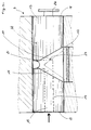
- this assembly being in particular characterized in that the supply channel connecting each extruder to the main channel is produced at least partially in a tap with cylindrical plug, which tap comprises means for transforming a cylindrical rod into a flat sheet.
- the meeting device 3 comprises a main channel 6 into which open channels 7 called feed channels carrying the different flows of material from the extruders, said channels 7 being provided with means 8 for restricting the flow passage section.
- the section of the main channel is, for example, rectangular and the longitudinal axis of the main channel is horizontal.
- the feed channel 7 connecting each extruder to the main channel 6 is produced at least partially in a tap 9 with a cylindrical plug, which tap 9 comprises means 10 for transforming a cylindrical rod into a flat sheet.
- the shapes of this skin are determined to transform a rod of circular section into a flat sheet.
- This form of skin is also called a carp tail shape.
- This arrangement of a ball valve is very advantageous because it allows very easy disassembly since it suffices to remove the valve along its axis of rotation.
- the terminal end of the draft 24 is shaped to direct the flow flowing between the bottom of the draft 24 and the internal face of the bore towards the slot made between the bore and the main channel.
- the external wall of the plug 13 located beyond the end edge of the draft 24 constitutes, for the slot connecting the bore and the main channel, a means of adjusting the passage section of this slot according to the position of this end edge by compared to the slot.
- the flow passage section is reduced by half.
- the cross section of the flow of the extruder can be varied and, for this, the face 18 of the plug opposite to that 17 in which the inlet opening of the axial channel 14 is provided is provided with: '' a gripping means 27.
- Another advantage of this arrangement is a reduction in the route which is very short between the extruder and the main channel.
- the angle defined by the two sides of the draft, the length measured between the intersection of these two sides and the end edge of this draft determine in particular the width of the sheet leaving the tap.
- This assembly device is very compact, which makes it possible to increase the number of extruders without increasing the heat losses and the pressure losses.
- the bushels are fed laterally.
- the slot in the bore communicates with the main channel by a short connecting channel formed in the thickness of the envelope of the main channel.
- the walls of said channel are formed by interchangeable cassettes 30, which cassettes constitute either the lower envelope of the main channel, or the upper envelope of this channel and are associated with each other according to a joint plane, which is preferably coplanar with the horizontal median plane of the main channel.
Landscapes
- Engineering & Computer Science (AREA)
- Mechanical Engineering (AREA)
- Manufacturing & Machinery (AREA)
- Extrusion Moulding Of Plastics Or The Like (AREA)
Claims (8)
- Vorrichtung zur Vereinigung von mindestens zwei Materialströmen zum Einsatz in einer Koextrusionslaminiermaschine, welche ihrerseits folgendes aufweist:- mindestens zwei Strangpressen (2), genauer gesagt ebenso viele Strangpressen (2) wie Schichten aus verschiedenen eingesetzten Werkstoffen vorgesehen sind,- eine Vorrichtung (3) zur Vereinigung der von den Strangpressen (2) kommenden Materialströme zu einem sogenannten Gesamtstrom, wobei diese Vorrichtung (3) auch als Verteilerbehälter bezeichnet wird,- einen Extrudierkopf (5), dem der Gesamtstrom zugeführt wird, und- Einrichtungen (10) zum Umformen des Materials aus einer zylinderförmigen Materialstange zu einer flachen Schicht,
wobei diese Vorrichtung zur Vereinigung einen Hauptkanal (6) aufweist, in welchen Nebenkanäle (7), sogenannte Zuführkanäle, einmünden, welche die verschiedenen, von den Strangpressen kommenden Materialströme führen, wobei die Kanäle (7) mit Einrichtungen (8) zur Verminderung des Stromdurchtrittsquerschnitts ausgerüstet sind,
dadurch GEKENNZEICHNET, daß der Zuführkanal (7), der jede Strangpresse mit dem Hauptkanal (6) verbindet, zumindest teilweise in einem Leitungsventil (9) mit zylinderförmigem Hahnkegel ausgebildet ist, wobei das Leitungsventil (9) die Einrichtungen (10) zum Umformen des Materials aus einer zylinderförmigen Materialstange zu einer flachen Schicht umfaßt. - Vorrichtung nach Anspruch 1, dadurch gekennzeichnet, daß das Leitungsventil (9) mit zylinderförmigem Hahnkegel folgendes aufweist:- einen Korpus mit einer zylindrischen Bohrung (11), die im wesentlichen tangential zur Ebene (P), in der sich der Materialstrom im Hauptkanal (6) verschiebt, mit diesem Hauptkanal (6) über einen Schlitz (12) in Verbindung steht, der parallel zur Längsachse der Bohrung verläuft,- ein zylinderförmiges Leitungsventil (13), das sich in der Bohrung (11) befindet und seinerseits folgendes aufweist:• einen axialen Kanal (14) mit zwei Enden (15, 16), von denen das eine (15) in eine (17) der gegenüberliegenden Flächen (17, 18) des Leitungsventils (13) einmündet und an welches sich zumindest indirekt die Strangpresse anschließt, und von denen das andere (16) mit einem (20) der Enden (20, 21) eines im wesentlichen radial verlaufenden Kanals in Verbindung steht, welcher mit seinem anderen Ende (21) in der Außenseite (22) des Leitungsventils (13) mündet, in deren Höhe diese Außenseite des Leitungsventils auf einem Teil ihres Umfangs eine Schrägung (24) aufweist, die in Richtung der Evolute eine Fächerform besitzt, deren Symmetrieachse sich in einer zur Drehachse des Leitungsventils (13) senkrechten Ebene befindet, so daß der Boden dieser Abschrägung und die Wandung der Bohrung einen als Zwischenkanal bezeichneten Kanal (26) bilden, welcher den axialen Kanal mit dem Bohrungsschlitz verbindet.
- Vorrichtung nach Anspruch 2, dadurch gekennzeichnet, daß die Formen dieser Abschrägung so bestimmt sind, daß ein Materialstrang mit kreisförmigem Querschnitt zu einer flachen Schicht umgeformt wird.
- Vorrichtung nach Anspruch 2, dadurch gekennzeichnet, daß- das Abschlußende der Abschrägung (24) so geformt ist, daß der zwischen dem Boden der Abschrägung (24) und der Innenfläche der Bohrung fließende Materialstrom zu dem zwischen der Bohrung und dem Hauptkanal ausgebildeten Schlitz geleitet wird, und- die Außenwandung des Leitungsventils (13), die sich jenseits der Abschlußkante der Abschrägung (24) befindet, für den die Bohrung mit dem Hauptkanal verbindenden Schlitz eine Einrichtung zum Einstellen des Durchtrittsquerschnitts dieses Schlitzes je nach Stellung dieser Abschlußkante bezüglich des Schlitzes bildet.
- Vorrichtung nach Anspruch 1 oder 2, dadurch gekennzeichnet, daß die Zuführung zu den Leitungsventilen seitlich erfolgt.
- Vorrichtung nach Anspruch 2, dadurch gekennzeichnet, daß der Schlitz der Bohrung mit dem Hauptkanal über einen kurzen Verbindungskanal in Strömungsverbindung steht, der in der Dicke der Ummantelung des Hauptkanals ausgebildet ist.
- Vorrichtung nach Anspruch 6, dadurch gekennzeichnet, daß die Dicke und die Breite des Hauptkanals aus austauschbaren Kassetten (30) gebildet sind.
- Vorrichtung nach Anspruch 7, dadurch gekennzeichnet, daß die austauschbaren Kassetten entlang einer Verbindungsebene unter Bildung einer oberen und unteren Ummantelung miteinander verbunden sind, wobei diese Verbindungsebene koplanar zur horizontalen Mittelebene des Hauptkanals verläuft.
Applications Claiming Priority (3)
| Application Number | Priority Date | Filing Date | Title |
|---|---|---|---|
| FR9313598 | 1993-11-09 | ||
| FR9313598A FR2712227B1 (fr) | 1993-11-09 | 1993-11-09 | Dispositif de réunion d'au moins deux flux dans une machine de coextrusion laminaire. |
| PCT/FR1995/000604 WO1996035570A1 (fr) | 1993-11-09 | 1995-05-09 | Dispositif de reunion d'au moins deux flux de matiere dans une machine de coextrusion laminaire |
Publications (2)
| Publication Number | Publication Date |
|---|---|
| EP0652097A1 EP0652097A1 (de) | 1995-05-10 |
| EP0652097B1 true EP0652097B1 (de) | 1997-09-10 |
Family
ID=9452857
Family Applications (1)
| Application Number | Title | Priority Date | Filing Date |
|---|---|---|---|
| EP94490051A Expired - Lifetime EP0652097B1 (de) | 1993-11-09 | 1994-10-27 | Vorrichtung zur Vereinigung von mindestens zwei Materialströmen in einer Koextrusionslaminierungsmaschine |
Country Status (4)
| Country | Link |
|---|---|
| EP (1) | EP0652097B1 (de) |
| AT (1) | ATE157924T1 (de) |
| DE (1) | DE69405512T2 (de) |
| FR (1) | FR2712227B1 (de) |
Families Citing this family (3)
| Publication number | Priority date | Publication date | Assignee | Title |
|---|---|---|---|---|
| WO1996035570A1 (fr) * | 1993-11-09 | 1996-11-14 | Extrusion De Basse Normandie - Exbanor, S.A. | Dispositif de reunion d'au moins deux flux de matiere dans une machine de coextrusion laminaire |
| US5971736A (en) * | 1995-05-09 | 1999-10-26 | Extrusion De Basse Normandie-Exbanor S.A. | Device for joining at least two material flows in a laminar coextrusion machine |
| CN107186985B (zh) * | 2017-06-16 | 2023-10-13 | 常州金纬管道科技有限公司 | 管材生产线的复合挤出系统 |
Family Cites Families (8)
| Publication number | Priority date | Publication date | Assignee | Title |
|---|---|---|---|---|
| USRE26237E (en) * | 1959-03-12 | 1967-07-18 | Manufacture of spectacle frames | |
| US3432588A (en) * | 1964-12-23 | 1969-03-11 | Dow Chemical Co | Method for the preparation of a filamentary reinforced resinous article having improved surface characteristics |
| US3734662A (en) * | 1971-02-08 | 1973-05-22 | Black Clawson Co | Flat film plastic extrusion apparatus |
| DE2534724C3 (de) * | 1975-08-04 | 1981-08-13 | Dynamit Nobel Ag, 5210 Troisdorf | Vorrichtung zum Extrudieren von gemusterten Bahnen oder Platten aus thermoplastischen Kunststoffmassen |
| DE2921943A1 (de) * | 1979-05-30 | 1980-12-11 | Waskoenig & Walter Kabel Werk | Verfahren zum wechseln der einfaerbung extrudierter kabelumhuellungen |
| DE3405744A1 (de) * | 1984-02-17 | 1985-08-22 | Hoechst Ag, 6230 Frankfurt | Vorrichtung zur herstellung mehrschichtiger verbundfolien |
| JPS63256418A (ja) * | 1987-04-15 | 1988-10-24 | Toray Ind Inc | 製膜口金 |
| US5137675A (en) * | 1991-05-13 | 1992-08-11 | Gencorp Inc. | Apparatus and method for coextruding materials having different temperature dependent properties |
-
1993
- 1993-11-09 FR FR9313598A patent/FR2712227B1/fr not_active Expired - Fee Related
-
1994
- 1994-10-27 DE DE69405512T patent/DE69405512T2/de not_active Expired - Fee Related
- 1994-10-27 EP EP94490051A patent/EP0652097B1/de not_active Expired - Lifetime
- 1994-10-27 AT AT94490051T patent/ATE157924T1/de not_active IP Right Cessation
Also Published As
| Publication number | Publication date |
|---|---|
| DE69405512D1 (de) | 1997-10-16 |
| FR2712227B1 (fr) | 1996-02-09 |
| EP0652097A1 (de) | 1995-05-10 |
| FR2712227A1 (fr) | 1995-05-19 |
| DE69405512T2 (de) | 1998-03-26 |
| ATE157924T1 (de) | 1997-09-15 |
Similar Documents
| Publication | Publication Date | Title |
|---|---|---|
| EP0677159B1 (de) | Mehrschichtrohr und extruderdüse für seine herstellung | |
| EP0236645B2 (de) | Vorrichtung und Verfahren zum Extrudieren von Kunststoffrohren mit mehrschichtigen Wänden | |
| FR2579516A1 (fr) | Bloc d'alimentation pour filiere plate de coextrusion | |
| EP0179521B1 (de) | Einstellbarer Beschickungsblock für eine Koextrudierdüse | |
| FR2625941A1 (fr) | Tete d'extrusion ou de co-extrusion en continu a orifices annulaires multiples | |
| EP2892655B1 (de) | Ausgabekopf zum sprühen eines fluids sowie ausgabevorrichtung mit einem solchen ausgabekopf | |
| CN101065022B (zh) | 用于挤压产品的设备和方法 | |
| EP0233434A1 (de) | Vorrichtung zur Verteilung von thermoplastischem Kunststoff zur Herstellung mehrschichtiger Folien | |
| EP0652097A1 (de) | Vorrichtung zur Vereinigung von mindestens zwei Materialströmen in einer Koextrusionslaminierungsmaschine | |
| CA1077220A (fr) | Dispositif de filieres pour la production de feuilles ou pellicules composites | |
| WO1996035570A1 (fr) | Dispositif de reunion d'au moins deux flux de matiere dans une machine de coextrusion laminaire | |
| CA2059118C (fr) | Profile a structure alveolaire en resine thermoplastique - appareillage d'extrusion pour l'obtention du profile et son procede de fabrication | |
| FR2859075A1 (fr) | Dispositif de distribution d'ecoulement pour une extrudeuse | |
| EP1708862B1 (de) | Kunststoffmaterialdosiersystem für kunststoffartikelherstellungsvorrichtung | |
| EP0020246B1 (de) | Vorrichtung zum Kühlen langer laminierter Wärmwalzprodukte | |
| EP1228977A1 (de) | Schaumstoffplatten aus thermoplastischem Material sowie Verfahren zu deren Herstellung | |
| EP3740372B1 (de) | Werkzeug zum dreidimensionalen auftragen von material durch extrusion | |
| US5971736A (en) | Device for joining at least two material flows in a laminar coextrusion machine | |
| FR2593112A1 (fr) | Filiere d'extrudeuse pour la fabrication d'une feuille soufflee multicouche. | |
| FR2924047A1 (fr) | Procede, dispositif et installation pour la fabrication de panneau par epandage de mousse synthetique | |
| FR2691048A1 (fr) | Groupe de co-extrusion pour la production d'un boudin de sucre cuit ou matière analogue à deux couleurs. | |
| FR2495053A1 (fr) | Machine d'extrusion en continu, ainsi que les produits extrudes obtenus | |
| EP0131669A1 (de) | Extrusionsgerät für weiche und plastische Materialien | |
| FR2693942A1 (fr) | Plaque alvéolaire pliable en matière plastique, procédé de fabrication de cette plaque et dispositif pour la mise en Óoeuvre du procédé. | |
| EP1282502B1 (de) | Extrusionskopfschmelzeverteiler und gebrauch des verteilers in einem extrusionskopf |
Legal Events
| Date | Code | Title | Description |
|---|---|---|---|
| PUAI | Public reference made under article 153(3) epc to a published international application that has entered the european phase |
Free format text: ORIGINAL CODE: 0009012 |
|
| AK | Designated contracting states |
Kind code of ref document: A1 Designated state(s): AT BE CH DE ES GB GR IT LI NL PT SE |
|
| 17P | Request for examination filed |
Effective date: 19950515 |
|
| 17Q | First examination report despatched |
Effective date: 19960627 |
|
| GRAG | Despatch of communication of intention to grant |
Free format text: ORIGINAL CODE: EPIDOS AGRA |
|
| GRAH | Despatch of communication of intention to grant a patent |
Free format text: ORIGINAL CODE: EPIDOS IGRA |
|
| GRAH | Despatch of communication of intention to grant a patent |
Free format text: ORIGINAL CODE: EPIDOS IGRA |
|
| GRAA | (expected) grant |
Free format text: ORIGINAL CODE: 0009210 |
|
| AK | Designated contracting states |
Kind code of ref document: B1 Designated state(s): AT BE CH DE ES GB GR IT LI NL PT SE |
|
| PG25 | Lapsed in a contracting state [announced via postgrant information from national office to epo] |
Ref country code: NL Free format text: LAPSE BECAUSE OF FAILURE TO SUBMIT A TRANSLATION OF THE DESCRIPTION OR TO PAY THE FEE WITHIN THE PRESCRIBED TIME-LIMIT Effective date: 19970910 Ref country code: IT Free format text: LAPSE BECAUSE OF FAILURE TO SUBMIT A TRANSLATION OF THE DESCRIPTION OR TO PAY THE FEE WITHIN THE PRE;WARNING: LAPSES OF ITALIAN PATENTS WITH EFFECTIVE DATE BEFORE 2007 MAY HAVE OCCURRED AT ANY TIME BEFORE 2007. THE CORRECT EFFECTIVE DATE MAY BE DIFFERENT FROM THE ONE RECORDED.SCRIBED TIME-LIMIT Effective date: 19970910 Ref country code: GR Free format text: LAPSE BECAUSE OF FAILURE TO SUBMIT A TRANSLATION OF THE DESCRIPTION OR TO PAY THE FEE WITHIN THE PRESCRIBED TIME-LIMIT Effective date: 19970910 Ref country code: ES Free format text: THE PATENT HAS BEEN ANNULLED BY A DECISION OF A NATIONAL AUTHORITY Effective date: 19970910 Ref country code: AT Effective date: 19970910 |
|
| REF | Corresponds to: |
Ref document number: 157924 Country of ref document: AT Date of ref document: 19970915 Kind code of ref document: T |
|
| REG | Reference to a national code |
Ref country code: CH Ref legal event code: EP |
|
| REF | Corresponds to: |
Ref document number: 69405512 Country of ref document: DE Date of ref document: 19971016 |
|
| PG25 | Lapsed in a contracting state [announced via postgrant information from national office to epo] |
Ref country code: SE Effective date: 19971210 Ref country code: PT Effective date: 19971210 |
|
| GBT | Gb: translation of ep patent filed (gb section 77(6)(a)/1977) |
Effective date: 19971124 |
|
| NLV1 | Nl: lapsed or annulled due to failure to fulfill the requirements of art. 29p and 29m of the patents act | ||
| PLBE | No opposition filed within time limit |
Free format text: ORIGINAL CODE: 0009261 |
|
| STAA | Information on the status of an ep patent application or granted ep patent |
Free format text: STATUS: NO OPPOSITION FILED WITHIN TIME LIMIT |
|
| 26N | No opposition filed | ||
| REG | Reference to a national code |
Ref country code: CH Ref legal event code: NV Representative=s name: SAEGER & PARTNER |
|
| PGFP | Annual fee paid to national office [announced via postgrant information from national office to epo] |
Ref country code: CH Payment date: 20011102 Year of fee payment: 8 |
|
| REG | Reference to a national code |
Ref country code: GB Ref legal event code: IF02 |
|
| PG25 | Lapsed in a contracting state [announced via postgrant information from national office to epo] |
Ref country code: LI Free format text: LAPSE BECAUSE OF NON-PAYMENT OF DUE FEES Effective date: 20021031 Ref country code: CH Free format text: LAPSE BECAUSE OF NON-PAYMENT OF DUE FEES Effective date: 20021031 |
|
| PGFP | Annual fee paid to national office [announced via postgrant information from national office to epo] |
Ref country code: GB Payment date: 20021121 Year of fee payment: 9 |
|
| PGFP | Annual fee paid to national office [announced via postgrant information from national office to epo] |
Ref country code: BE Payment date: 20021129 Year of fee payment: 9 |
|
| PGFP | Annual fee paid to national office [announced via postgrant information from national office to epo] |
Ref country code: DE Payment date: 20021210 Year of fee payment: 9 |
|
| REG | Reference to a national code |
Ref country code: CH Ref legal event code: PL |
|
| PG25 | Lapsed in a contracting state [announced via postgrant information from national office to epo] |
Ref country code: GB Free format text: LAPSE BECAUSE OF NON-PAYMENT OF DUE FEES Effective date: 20031027 |
|
| PG25 | Lapsed in a contracting state [announced via postgrant information from national office to epo] |
Ref country code: BE Free format text: LAPSE BECAUSE OF NON-PAYMENT OF DUE FEES Effective date: 20031031 |
|
| BERE | Be: lapsed |
Owner name: *VELLUIRE MAURICE Effective date: 20031031 Owner name: S.A. *EXTRUSION DE BASSE NORMANDIE-EXBANOR Effective date: 20031031 |
|
| PG25 | Lapsed in a contracting state [announced via postgrant information from national office to epo] |
Ref country code: DE Free format text: LAPSE BECAUSE OF NON-PAYMENT OF DUE FEES Effective date: 20040501 |
|
| GBPC | Gb: european patent ceased through non-payment of renewal fee |
Effective date: 20031027 |