EP0652374B1 - Betriebssteuersystem für Turboströmungsmaschinen - Google Patents
Betriebssteuersystem für Turboströmungsmaschinen Download PDFInfo
- Publication number
- EP0652374B1 EP0652374B1 EP94116413A EP94116413A EP0652374B1 EP 0652374 B1 EP0652374 B1 EP 0652374B1 EP 94116413 A EP94116413 A EP 94116413A EP 94116413 A EP94116413 A EP 94116413A EP 0652374 B1 EP0652374 B1 EP 0652374B1
- Authority
- EP
- European Patent Office
- Prior art keywords
- rotational speed
- fluid machine
- pressure
- operating head
- capacity
- Prior art date
- Legal status (The legal status is an assumption and is not a legal conclusion. Google has not performed a legal analysis and makes no representation as to the accuracy of the status listed.)
- Expired - Lifetime
Links
- 239000012530 fluid Substances 0.000 title claims description 55
- 230000007423 decrease Effects 0.000 claims description 23
- 238000000034 method Methods 0.000 claims description 11
- 238000002485 combustion reaction Methods 0.000 claims description 9
- 230000004044 response Effects 0.000 claims description 4
- 230000008859 change Effects 0.000 description 15
- 239000007788 liquid Substances 0.000 description 11
- 230000002349 favourable effect Effects 0.000 description 10
- 230000006698 induction Effects 0.000 description 8
- 230000001276 controlling effect Effects 0.000 description 7
- 230000003068 static effect Effects 0.000 description 7
- 230000000694 effects Effects 0.000 description 6
- 239000000446 fuel Substances 0.000 description 4
- 230000009471 action Effects 0.000 description 3
- 238000007796 conventional method Methods 0.000 description 3
- 230000001105 regulatory effect Effects 0.000 description 2
- 230000033228 biological regulation Effects 0.000 description 1
- 239000003638 chemical reducing agent Substances 0.000 description 1
- 239000000470 constituent Substances 0.000 description 1
- 230000006872 improvement Effects 0.000 description 1
- 230000007246 mechanism Effects 0.000 description 1
- 230000004048 modification Effects 0.000 description 1
- 238000012986 modification Methods 0.000 description 1
- 230000008569 process Effects 0.000 description 1
Images


Classifications
-
- F—MECHANICAL ENGINEERING; LIGHTING; HEATING; WEAPONS; BLASTING
- F04—POSITIVE - DISPLACEMENT MACHINES FOR LIQUIDS; PUMPS FOR LIQUIDS OR ELASTIC FLUIDS
- F04D—NON-POSITIVE-DISPLACEMENT PUMPS
- F04D13/00—Pumping installations or systems
- F04D13/02—Units comprising pumps and their driving means
- F04D13/04—Units comprising pumps and their driving means the pump being fluid driven
-
- F—MECHANICAL ENGINEERING; LIGHTING; HEATING; WEAPONS; BLASTING
- F04—POSITIVE - DISPLACEMENT MACHINES FOR LIQUIDS; PUMPS FOR LIQUIDS OR ELASTIC FLUIDS
- F04D—NON-POSITIVE-DISPLACEMENT PUMPS
- F04D15/00—Control, e.g. regulation, of pumps, pumping installations or systems
- F04D15/0066—Control, e.g. regulation, of pumps, pumping installations or systems by changing the speed, e.g. of the driving engine
-
- F—MECHANICAL ENGINEERING; LIGHTING; HEATING; WEAPONS; BLASTING
- F04—POSITIVE - DISPLACEMENT MACHINES FOR LIQUIDS; PUMPS FOR LIQUIDS OR ELASTIC FLUIDS
- F04D—NON-POSITIVE-DISPLACEMENT PUMPS
- F04D27/00—Control, e.g. regulation, of pumps, pumping installations or pumping systems specially adapted for elastic fluids
- F04D27/004—Control, e.g. regulation, of pumps, pumping installations or pumping systems specially adapted for elastic fluids by varying driving speed
-
- Y—GENERAL TAGGING OF NEW TECHNOLOGICAL DEVELOPMENTS; GENERAL TAGGING OF CROSS-SECTIONAL TECHNOLOGIES SPANNING OVER SEVERAL SECTIONS OF THE IPC; TECHNICAL SUBJECTS COVERED BY FORMER USPC CROSS-REFERENCE ART COLLECTIONS [XRACs] AND DIGESTS
- Y02—TECHNOLOGIES OR APPLICATIONS FOR MITIGATION OR ADAPTATION AGAINST CLIMATE CHANGE
- Y02B—CLIMATE CHANGE MITIGATION TECHNOLOGIES RELATED TO BUILDINGS, e.g. HOUSING, HOUSE APPLIANCES OR RELATED END-USER APPLICATIONS
- Y02B30/00—Energy efficient heating, ventilation or air conditioning [HVAC]
- Y02B30/70—Efficient control or regulation technologies, e.g. for control of refrigerant flow, motor or heating
Definitions
- the present invention relates to a system for controlling the operation of a turbo type fluid machine. More particularly, the present invention relates to a turbo type fluid machine operation control system which enables a turbo machine, e.g., a pump, a blower, etc., to exhibit favorable performance characteristics in conformity to each particular purpose of use.
- a turbo machine e.g., a pump, a blower, etc.
- a technique whereby the rotational speed of a driving machine for the turbo machine is varied has been widely employed.
- the rotational speed is varied so that the head or pressure produced by the turbo machine or the capacity (i.e., discharge quantity) thereof complies with the demand therefor, thereby controlling the characteristics of the fluid machine. That is, in automatic control, the rotational speed is feedback-controlled on the basis of the result of a comparison between the value of the detected quantity, e.g., the discharge pressure, capacity, etc., on the demand side and the corresponding set value.
- Japanese Patent Application Public Disclosure (KOKAI) Nos. 57-52396 and 59-44997 disclose a method wherein the invertor is controlled so that the operating efficiency of the motor is maximized.
- Japanese Patent Application Public Disclosure (KOKAI) No. 59-25099 discloses a control method wherein the motor output is maintained at the rated value by an invertor.
- Japanese Patent Application Post-Examination Publication No. 57-113992 discloses a method wherein a rotational speed that gives a target pressure is arithmetically obtained to control the speed of a pump.
- the pressure-capacity curve assumes a convex shape with a maximum value in a small capacity region as is observed in a centrifugal blower or the like. Therefore, the operational range is limited to the capacity region above the capacity value at which the pressure reaches a maximum in order to avoid surging.
- the present invention provides a turbo type fluid machine operation control system including a turbo type fluid machine driven by a driving machine, and a device for detecting an operating head or operating pressure of the fluid machine.
- the operation control system further includes a device for arithmetically outputting a rotational speed which gives a preset characteristic of the fluid machine in corresponding relation to the operating head or operating pressure, and a device for changing the rotational speed of the driving machine in response to the output rotational speed, so that even when the operating head or operating pressure of the fluid machine changes, the rotational speed of the fluid machine is controlled so as to maintain the preset characteristic of the fluid machine.
- a rotational speed signal that gives a preset performance characteristic of the fluid machine is input to a speed governor or rotational speed controller for the driving machine to control the rotational speed thereof. Accordingly, favorable performance characteristics can be maintained at all times irrespective of change in the operating head or pressure.
- the rotational speed is controlled so that a constant torque, as the above-described preset performance characteristic, is maintained at all times irrespective of change in the operating head or pressure it is generally possible to realize characteristics favorable for actual use while utilizing the capacity of the prime mover to the full. That is, in the case of a high specific speed fluid machine, when the operating head or pressure is below the rated value, the rotational speed increases, and the capacity increases. On the other hand, in a low capacity region where the operating head or pressure is above the rated value, the rotational speed decreases, and the required power decreases. Therefore, overloading of the driving machine can be avoided.
- Figs. 1 to 8 show a first embodiment of the present invention.
- Fig. 1 illustrates the basic arrangement of a first embodiment of the operation control system according to the present invention in which the invention is applied to a turbo type drainage pump.
- the drainage pump 1 is a turbo type high specific speed pump, i.e., an axial flow pump or a mixed flow pump, which is used for a relatively large capacity and a low pump head.
- the pump 1 is driven by a driving machine 3 via a speed reducer 2.
- the driving machine 3 may be an internal combustion engine, a gas turbine, or a steam turbine.
- the driving machine 3 has a speed governor 4 for controlling the speed of rotation of the driving machine 3.
- a function generator 5 is an arithmetic device for outputting a rotational speed n which gives a constant torque in corresponding relation to the operating head Ha of the pump 1.
- a rotational speed detector 7 is a device for detecting the rotational speed of the rotating shaft of the driving machine 3 and for outputting it in the form of an electrical signal.
- a comparator amplifier 6 makes a comparison between the rotational speed signal detected by the rotational speed detector 7 and the rotational speed signal corresponding to the operating head, which is output from the function generator 5, and outputs deviation of the former rotational speed signal from the latter rotational speed signal to the speed governor 4.
- the function generator 5 is fed with a signal indicative of the actual pump head Ha from the liquid level gauge (not shown) and outputs a signal indicative of a rotational speed n that gives a constant torque for the pump.
- the comparator amplifier 6 is fed with a signal from the rotational speed detector 7 that corresponds to the actual rotational speed of the pump 1 to compare it with the signal indicative of the rotational speed n, which is output from the function generator 5. Deviation of the actual rotational speed from the rotational speed n, which is determined by the comparator amplifier 6, is input to the speed governor 4.
- the speed governor 4 controls the fuel feed rate according to the deviation, thereby varying the speed of the driving machine 3.
- the rotational speed signal n from the function generator 5 increases in accordance with the corresponding actual pump head Ha so that the torque is maintained at a constant level.
- the comparator amplifier 6 detects deviation of the actual rotational speed from the rotational speed n, and the speed governor 4 increases the fuel feed rate according to the deviation, thereby increasing the rotational speed of the driving machine 3 to the required value.
- the function generator 5 outputs a signal for reducing the rotational speed so that the torque is maintained at a constant level.
- the comparator amplifier 6 compares the signal which is output from the function generator 5 with the signal which is output from the rotational speed detector 7, and the speed governor 4 reduces the output of the driving machine 3 according to the result of the comparison, thereby lowering the rotational speed to the required value.
- a group of relationship curves can be drawn with regard to rotational speeds below and above the rated point according to the equation (1) on the basis of known relationship curves of the pump head and shaft power relative to the capacity at the rated speed. It is possible to obtain a rotational speed on the group of curves that satisfies the rated point and yet satisfies the relationship to any pump head or torque or shaft power at capacities below and above the rated point.
- the operation control system of the present invention is realized by setting in the function generator stated in appended Claim 3 a relationship between the operating head and the rotational speed which gives the above-described characteristics in corresponding relation to the operating head.
- Figs. 2 and 3 respectively show the relationships between the pump head H and the capacity Q and between the power Lp and the capacity Q.
- the dotted lines H (N const.), Lp (N const.) show the relationships in the conventional operation in which the rotational speed is maintained at a constant value.
- the solid lines H (T const.), Lp (T const.) show the relationships in the first embodiment of the present invention, in which the rotational speed of the driving machine is varied with the torque maintained at a constant value.
- the rotational speed is reduced in a small discharge region below the rated capacity (100%), where the shaft power increases, whereas in a discharge region above the rated capacity, the rotational speed is increased because the shaft power decreases in this region, thus maintaining the torque at the value of the rated point over the entire range.
- the operating head of a drainage pump or other similar pump is given as the sum H of the difference between the internal and external liquid levels, that is, the actual head Ha, and the loss R of head in the piping in front of and behind the pump.
- the piping loss R varies in proportion to the square of the capacity Q. Therefore, it can be expressed as a system head curve R shown in Fig. 4 based on the value at the rated capacity.
- a rotational speed that gives a constant torque which is determined from the readily measurable actual head through the use of the relationship shown in Fig. 5, is set in the function generator 5, and the set value of the rotational speed and the detected value from the rotational speed detector 7 are input to the comparator amplifier 6, where deviation of the detected value from the set value is obtained. Then, a speed increasing or reducing signal corresponding to the deviation is given to the speed governor 4, thereby enabling the pump to be operated with a constant torque irrespective of change in the operating head of the pump. It is also possible to operate the pump with a desired torque by changing the setting of a function of the relation between the actual head and the rotational speed.
- the high specific speed pump 1 in which the torque is maintained at a constant value, the high specific speed pump 1 can be favorably operated as follows: In a discharge region above the rated capacity, the rotational speed N rises, and the capacity Q increases to a considerable extent. In a small discharge region, on the other hand, the rotational speed N decreases, so that it is possible to avoid overloading of the driving machine 3.
- the pump operation can be started or stopped with the discharge valve fully closed. Thus, it is possible to avoid a rapid change in the capacity at the time of starting or stopping the pump operation.
- High specific speed pumps are generally employed as drainage pumps or other similar pumps which are used for a relatively low operating head.
- the operating head varies to a considerable extent according to the difference between the internal and external liquid levels.
- the slope of the pump head (H-Q) curve becomes flat, the capacity increases when the pump head is low, that is, when the internal liquid level is high, thereby enabling the time required for drainage to be shortened.
- the dot-dash line R A shows a system head curve when the pump head is at the rated value
- R B a system head curve when the pump head is low. That is, the operating point B in the case of a pump operated at the constant speed shifts to the point C.
- a rotational speed upper limit setting device 8 is inserted in the feedback loop to limit the rotational speed of the driving machine 3 and the pump 1 within a predetermined value.
- Figs. 6 and 7 respectively show the relationships between the pump efficiency e P and the capacity Q and between the required NPSH (Net Positive Suction Head) and the capacity Q with the value at the rated point being defined as 100%.
- the roundness of the pump efficiency curve is prominent in comparison to the pump efficiency curve in the case of the constant-speed operation, which is shown by the dotted line.
- the efficiency e P when the capacity Q is large.
- an energy-saving operation is realized.
- the value of the required NPSH of a high specific speed pump increases below and above the rated capacity.
- the capacity Q that gives the minimum value of NPSH shifts together with the rotational speed N. Therefore, the rate at which the required NPSH increases at capacities below and above the rated value is relatively low; this is advantageous from the viewpoint of installing or operating the pump.
- Fig. 8 shows another embodiment of the pump operation control system according to the present invention, in which the rotational speed is varied with the torque maintained at a constant level.
- the basic arrangement of this embodiment is the same as that shown in Fig. 1.
- Constituent elements of the arrangement shown in Fig. 8 which have the same functions as those in the first embodiment are denoted by the same reference numerals, and description thereof is omitted.
- a torque detector 9 detects the torque output from the rotating shaft of the driving machine 3. The detected torque is compared in a comparator amplifier 14 with a torque set in a torque setting device 13.
- the speed governor 4 varies the fuel feed rate according to the deviation of the detected torque from the set value, thereby changing the speed of rotation, and thus effecting control so that the torque reaches a preset constant value.
- the rotational speed of the pump is controlled so that the torque is maintained at a constant level. Therefore, the operation and advantageous effects of the control system are the same as those in the above-described embodiment.
- an internal combustion engine, a gas turbine, or a steam turbine is employed as the driving machine 3.
- an electric motor is employed as the driving machine 3.
- the rotational speed of the pump can be controlled so that the torque is maintained at a constant level by driving an induction motor by the use of a rotational speed controller, e.g., a frequency-voltage converter (static invertor), in place of the speed governor 4.
- Figs. 9 to 12 show a second embodiment of the present invention.
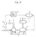
- Fig. 9 illustrates the basic arrangement of a second embodiment of the operation control system according to the present invention in which the invention is applied to a turbo type low specific speed pump.
- the pump 11 is a low specific speed centrifugal pump that is used for a relatively high pump head.
- the pump 1 is driven by a driving machine 3, e.g., an electric motor, a steam turbine, etc.
- the driving machine 12 has a rotational speed controller 14 for controlling the speed of rotation thereof.
- the operating head of the pump 1 is detected by an arithmetic unit 22 that obtains a pressure difference through a pressure detector 20 on the discharge side and a pressure detector 21 on the suction side.
- a function generator 15 is an arithmetic device for outputting a rotational speed n which gives a constant torque in corresponding relation to the operating head H of the pump 1.
- a rotational speed detector 17 is a device for detecting the speed of rotation of the driving machine 3 and for outputting it in the form of an electrical signal. In a case where the driving machine 3 is an induction motor and the rotational speed controller 14 is a static invertor, an output frequency detector may be used in place of the rotational speed detector 17.
- a comparator amplifier 16 makes a comparison between the rotational speed signal which is output from the rotational speed detector 17 and the rotational speed signal corresponding to the operating head, which is output from the function generator 15, and outputs deviation of the former rotational speed signal from the latter rotational speed signal to the rotational speed controller 14.
- the rotational speed controller 14 varies the rotational speed of the driving machine 3 according to the deviation, thereby enabling the pump 1 to be operated with a constant torque irrespective of change in the operating head.
- the driving machine 3 is an induction motor
- a static invertor or the like in which the ratio of frequency to voltage is constant is employed as the rotational speed controller 14
- the generated torque corresponding to the motor current value is constant, as is generally known.
- the rated output of an electric motor is regulated by the value of temperature rise caused by the motor current. Accordingly, by maintaining the torque of the pump at a value corresponding to the rated current value of the motor, it is possible to realize an operation in which the capacity of the electric motor can be exhibited to the full irrespective of change in the operating head or capacity of the pump.
- the electric motor displays the maximum efficiency in the region of the rated current value, it is possible to perform a highly efficient operation at all times.
- Fig. 10 shows the relationship between the pump head H and the capacity Q.
- Fig. 11 shows the relationship between the capacity Q and the shaft power Lp.
- the dotted lines show the relationships in the case of the conventional operation in which the rotational speed is maintained at a constant value.
- the solid lines A show the relationships in the second embodiment of the present invention in which the rotational speed is varied with the torque of the driving machine maintained at a constant value. That is, in a low capacity region below the rated capacity (100%), in which the shaft power decreases, the rotational speed is increased, whereas in a high capacity region above the rated capacity, the rotational speed is reduced because the shaft power increases in this region, thereby maintaining the torque at the value of the rated point over the entire range.
- the capacity of the driving machine can be effectively utilized. Moreover, since the angle of inclination of the H-Q curve of the pump with respect to the axis Q is large, the change in the capacity Q is remarkably small even when the operating head H shifts up or down from the rated value. Thus, it is possible to realize characteristics favorable for actual use.
- a rotational speed upper limit setting device 18 is provided for the rotational speed controller 14 to limit the rotational speed to a predetermined value.
- the rotational speed controller 14 can be feedback-controlled by setting in the function generator 15 the rotational speed corresponding to the operating head on the basis of the characteristics of the pump used so that an H-Q curve with a desired slope is realized by using a similar device to the above, and comparing the detected value of rotational speed with the set value.
- the function of the relation between the operating head and the rotational speed is shown by the curve ⁇ in Fig. 12 in correspondence to the H-Q curve shown by B in Fig. 10.
- the H-Q curve of the pump is a straight line C that is at right angles to the axis Q, and the relationship between the operating head and the rotational speed is shown by the curve ⁇ in Fig. 12.
- an H-Q curve which is steeper than the H-Q curve denoted by A in Fig. 10 i.e., the H-Q curve B or C in Fig. 10
- Figs. 13 to 16 show a third embodiment of the present invention.
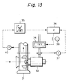
- Fig. 13 illustrates the basic arrangement of a third embodiment of the operation control system according to the present invention in which the invention is applied to a turbo blower.
- the blower 31 is a turbo blower or fan with radial vanes, which is driven by an induction motor 32.
- the speed of rotation of the induction motor 32 is controlled by a static invertor 34.
- the operating pressure of the blower 31 is input as an electric signal to a function generator 35 by a pressure detecting converter 40 on the discharge side of the blower 31.
- the function generator 35 is an arithmetic device for outputting a rotational speed n which gives a constant torque in corresponding relation to the operating pressure of the blower 31.
- a frequency detector 37 on the secondary side of the static invertor 34 inputs a signal indicative of the rotational speed of the induction motor 32 to a comparator amplifier 36.
- the comparator amplifier 36 makes a comparison between the rotational speed n given by the function generator 35 and the actual rotational speed detected by the frequency detector 37 and inputs deviation obtained by the comparison to the frequency varying part of the static invertor 34, thereby controlling the rotational speed of the induction motor 32 so that a constant torque is given irrespective of change in the operating pressure.
- Figs. 14 and 15 respectively show the relationships between the operating pressure P and the capacity Q and between the torque T and the capacity Q with the rated point being defined as 100%.
- the dotted lines show the relationships in the case of an operation performed with the rotational speed maintained at a constant value.
- the solid lines show the relationships in the third embodiment of the present invention in which the rotational speed is controlled with the torque maintained at a constant value.
- Fig. 15 also shows the rotational speed N which gives a constant torque in corresponding relation to the capacity Q.
- the curve N in Fig. 15 shows the rate of change in the motor output with respect to the capacity Q because the shaft power is expressed by the product of the torque T and the rotational speed N. Since the motor current is held constant when the torque is maintained at a constant value, the motor capacity can be utilized to the full at all times irrespective of variation in the operating pressure.
- the characteristic curve of the operating pressure P relative to the capacity Q often assumes a convex shape with a maximum value around 50% of the rated capacity. In a capacity region below the capacity value at which the pressure P reaches a maximum, surging occurs, making it impossible to perform a stable operation.
- the characteristic curve of the pressure P relative to the capacity Q becomes a downward sloped curve which is stable over a wide range of operating pressure variations, as shown in Fig. 14.
- the surging limit can be excluded from the entire capacity range.
- characteristics favorable for actual use can be realized.
- Fig. 16 shows the relationship between the operating pressure, which is obtained by using the relationship between the torque and the rotational speed obtained from the equation (1), and the rotational speed that gives a constant torque.
- the relationship shown in the figure is set in the function generator 35.
- An excessive rise in the rotational speed caused by the rise in the operating pressure is avoided by a rotational speed upper limit setting device 38.
- the present invention provides the following advantageous effects:
- a turbo type fluid machine that is driven by a prime mover provided with a speed governor or a rotational speed controller, it is possible to realize performance characteristics favorable for actual use by detecting only the operating head or the operating pressure, which is readily measurable.
- it is possible to improve markedly the performance characteristics of the fluid machine e.g., the relationship between the operating head or pressure and the capacity.
- the present invention is widely applicable to turbo type pumps, blowers, etc. which are driven by various variable speed prime movers.
Landscapes
- Engineering & Computer Science (AREA)
- Mechanical Engineering (AREA)
- General Engineering & Computer Science (AREA)
- Control Of Non-Positive-Displacement Pumps (AREA)
- Control Of Positive-Displacement Air Blowers (AREA)
- Control Of Positive-Displacement Pumps (AREA)
Claims (7)
- Betriebssteuersystem für Turboströmungsmaschinen, wobei folgendes vorgesehen ist:eine durch eine Antriebsmaschine (3, 32) angetriebene Turboströmungsmaschine (1, 31);Mittel (20, 21, 40) zum Detektieren eines Betriebsdrucks der Strömungsmaschine;Mittel (5, 15, 35) zur arithmetischen Ausgabe einer Drehzahl;Mittel (4, 14, 34) zur Änderung einer Drehzahl der Antriebsmaschine ansprechend auf die arithmetisch ausgegebene Drehzahl; undMittel (8, 18, 38) zum Vorsehen einer oberen Grenze für einen eingestellten Drehzahlwert an die Mittel zur Änderung einer Drehzahl der Antriebsmaschine gegeben, um die Drehzahl der Antriebsmaschine und der Strömungsmaschine innerhalb eines vorbestimmten Wertes zu begrenzen, dadurch gekennzeichnet, daßdie arithmetisch ausgegebene Drehzahl ein voreingestelltes konstantes Drehmoment der Strömungsmaschine erzeugt, um die Verwendung der gesamten Kapazität der Antriebsmaschine in entsprechender Beziehung mit dem Betriebsdruck zu gestatten, und wobei selbst wenn sich der Betriebsdruck der Strömungsmaschine ändert eine Drehzahl der Strömungsmaschine derart gesteuert wird, um so das voreingestellte konstante Drehmoment aufrecht zu erhalten, so daß für eine Strömungsmaschine mit hoher spezifischer Drehzahl dann, wenn der Betriebsdruck oder Druck unterhalb eines Nennwertes ist, die Drehzahl ansteigt und die Pumpenkapazität sich vergrößert; und wobei, wenn der Betriebsdruck oder Druck oberhalb des Nennwertes liegt die Drehzahl abnimmt und die Pumpenkapazität abnimmt, um eine Überlastung der Antriebsmaschine zu vermeiden; und daß für eine Strömungsmaschine für eine niedrige spezifische Drehzahl dann, wenn der Betriebsdruck oder Druck oberhalb des Nennwertes liegt die Drehzahl ansteigt und die Abnahme der Pumpenkapazität vermindert wird; und daß dann, wenn der Betriebsdruck oder Druck unterhalb des Nennwertes liegt, die Drehzahl abnimmt, um einen übermäßigen Anstieg der Pumpenkapazität zu verhindern um eine Überlastung der Antriebsmaschine zu vermeiden.
- Betriebssteuersystem für Turboströmungsmaschinen nach Anspruch 1, wobei die Mittel zur arithmetischen Ausgabe einer Drehzahl einen Funktionsgenerator (5, 15, 35), einen Detektor (7, 17, 37) zum Detektieren der Drehzahl der Strömungsmaschine und einen Vergleichsverstärker (6, 16, 36) aufweisen.
- Betriebssteuersystem für Turboströmungsmaschinen nach Anspruch 1, wobei die Antriebsmaschine ein Verbrennungsmotor (3) ist, eine Gasturbine, oder eine Dampfturbine, und wobei die Mittel zur Änderung der Drehzahl der Antriebsmaschine einen Drehzahlregler (4, 14) aufweisen.
- Betriebssteuersystem für Turboströmungsmaschinen nach Anspruch 1, wobei die Antriebsmaschine ein Elektromotor (32) ist, und wobei die Mittel zur Änderung der Drehzahl der Antriebsmaschine eine Drehzahlsteuervorrichtung (34) aufweisen.
- Betriebssteuersystem für Turboströmungsmaschinen nach Anspruch 4, wobei die Drehzahlsteuervorrichtung ein Frequenz-Spannungsumwandler ist.
- Verfahren zur Steuerung einer Turboströmungsmaschine (1), angetriebenen durch einen Verbrennungsmotor (3), wobei die folgenden Schritte vorgesehen sind:Detektieren eines Betriebsdrucks der Strömungsmaschine;arithmetisches Ausgeben einer Drehzahl;Änderung einer Drehzahl des Verbrennungsmotors ansprechend auf die arithmetische Ausgabe der Drehzahl; undBegrenzen der Drehzahl der Strömungsmaschine innerhalb eines vorbestimmten Wertes; dadurch gekennzeichnet, daß:die Drehzahl ein konstantes Drehmoment der Strömungsmaschine ergibt in entsprechende Beziehung zum Betriebsdruck um die Verwendung der gesamten Kapazität des Verbrennungsmotors zu gestatten, und wobei selbst wenn sich der Betriebsdruck der Strömungsmaschine ändert eine Drehzahl der Strömungsmaschine so gesteuert wird, daß das erwähnte konstante Drehmoment aufrecht erhalten wird, derart, daß für eine Strömungsmaschine mit hoher spezifischer Drehzahl dann, wenn der Betriebsdruck unterhalb eines Nennwertes liegt die Drehzahl ansteigt und die Pumpenkapazität ansteigt; und daß dann, wenn der Betriebsdruck oberhalb des Nennwertes ist, die Drehzahl abnimmt und die Pumpenkapazität abnimmt, um ein Überlasten des Verbrennungsmotors zu vermeiden, und daß ferner für eine Strömungsmaschine mit einer niedrigen spezifischen Drehzahl dann, wenn der Betriebsdruck oberhalb des Nennwertes liegt die Drehzahl ansteigt und der Anstieg der Pumpenkapazität reduziert wird; und daß dann, wenn der Betriebsdruck unterhalb des Nennwertes liegt die Drehzahl abnimmt, um einen übermäßigen Anstieg der Pumpenkapazität zu verhindern, um das Überlasten der Antriebsmaschine zu vermeiden.
- Verfahren zum Steuern einer Turboströmungsmaschine nach Anspruch 6, wobei die obere Grenze zur Begrenzung der Drehzahl der Strömungsmaschine innerhalb des vorbestimmten Wertes vorgesehen ist.
Applications Claiming Priority (2)
| Application Number | Priority Date | Filing Date | Title |
|---|---|---|---|
| JP285770/93 | 1993-10-21 | ||
| JP28577093A JP3373012B2 (ja) | 1993-10-21 | 1993-10-21 | ターボ形流体機械の運転制御装置 |
Publications (2)
| Publication Number | Publication Date |
|---|---|
| EP0652374A1 EP0652374A1 (de) | 1995-05-10 |
| EP0652374B1 true EP0652374B1 (de) | 1999-01-27 |
Family
ID=17695837
Family Applications (1)
| Application Number | Title | Priority Date | Filing Date |
|---|---|---|---|
| EP94116413A Expired - Lifetime EP0652374B1 (de) | 1993-10-21 | 1994-10-18 | Betriebssteuersystem für Turboströmungsmaschinen |
Country Status (4)
| Country | Link |
|---|---|
| US (1) | US5634772A (de) |
| EP (1) | EP0652374B1 (de) |
| JP (1) | JP3373012B2 (de) |
| DE (1) | DE69416247T2 (de) |
Families Citing this family (18)
| Publication number | Priority date | Publication date | Assignee | Title |
|---|---|---|---|---|
| US6053703A (en) * | 1995-06-19 | 2000-04-25 | Ebara Corporation | Control method for displacement-type fluid machine, and apparatus thereof |
| US6464464B2 (en) * | 1999-03-24 | 2002-10-15 | Itt Manufacturing Enterprises, Inc. | Apparatus and method for controlling a pump system |
| JP2001123984A (ja) * | 1999-10-25 | 2001-05-08 | Tsurumi Mfg Co Ltd | 水中モータを原動機とする斜流または軸流ポンプの運転制御方法および装置 |
| AR029828A1 (es) * | 2001-07-13 | 2003-07-16 | Petrobras En S A | Metodo para la regulacion primaria de frecuencia en turbinas de vapor de ciclo combinado |
| US6564627B1 (en) * | 2002-01-17 | 2003-05-20 | Itt Manufacturing Enterprises, Inc. | Determining centrifugal pump suction conditions using non-traditional method |
| WO2004072485A1 (en) * | 2003-02-05 | 2004-08-26 | Engineered Support Systems, Inc. | Digital pressure controller for pump assembly |
| JP4726424B2 (ja) * | 2004-03-25 | 2011-07-20 | 富士工業株式会社 | 送風機の風量制御方法 |
| JP4675057B2 (ja) * | 2004-05-06 | 2011-04-20 | 株式会社鶴見製作所 | 渦巻きポンプの運転制御方法 |
| JP4675056B2 (ja) * | 2004-05-06 | 2011-04-20 | 株式会社鶴見製作所 | 軸流または斜流ポンプの運転制御方法 |
| ITFI20120125A1 (it) | 2012-06-19 | 2013-12-20 | Nuovo Pignone Srl | "wet gas compressor and method" |
| US11460016B1 (en) | 2013-03-14 | 2022-10-04 | Tucson Embedded Systems, Inc. | Controller assembly for simultaneously managing multiple engine/pump assemblies to perform shared work |
| FR3007086B1 (fr) * | 2013-06-18 | 2015-07-03 | Cryostar Sas | Roue centrifuge |
| EP2910788B1 (de) * | 2014-02-25 | 2018-04-04 | TACO ITALIA S.r.l. | Verfahren zur Steuerung einer Pumpstation in einem Fluidzirkulationssystem, zugehöriges Zirkulationssystem und Pumpstation zur Durchführung dieses Verfahrens |
| NO338576B1 (no) * | 2014-09-16 | 2016-09-05 | Fmc Kongsberg Subsea As | System for pumping av et fluid og fremgangsmåte for dens drift. |
| CN109322839A (zh) * | 2017-08-01 | 2019-02-12 | 上海东新冶金技术工程有限公司 | 可连续工作用于热镀锌的耐高温排渣离心泵及其使用方法 |
| JP2021032193A (ja) * | 2019-08-28 | 2021-03-01 | 株式会社荏原製作所 | ポンプ装置 |
| US20230243361A1 (en) * | 2020-07-30 | 2023-08-03 | Mitsubishi Electric Corporation | Blower and method for controlling blower |
| JP2023037590A (ja) * | 2021-09-03 | 2023-03-15 | 株式会社マキタ | 送風機から吐出される空気の流量が低下することを抑制する技術 |
Family Cites Families (18)
| Publication number | Priority date | Publication date | Assignee | Title |
|---|---|---|---|---|
| US3832846A (en) * | 1972-04-27 | 1974-09-03 | Woodward Governor Co | Speed governor with fuel rate control |
| US3985467A (en) * | 1975-05-27 | 1976-10-12 | Milton Roy Company | Constant pressure pump |
| AT364252B (de) * | 1980-05-20 | 1981-10-12 | Rosenbauer Kg Konrad | Feuerloeschkreiselpumpe |
| JPS5752396A (en) * | 1980-09-16 | 1982-03-27 | Toshiba Corp | Speed control device of induction motor |
| JPS57113992A (en) * | 1981-01-07 | 1982-07-15 | Hitachi Ltd | Pump velocity controlling process |
| JPS58183893A (ja) * | 1982-04-21 | 1983-10-27 | Hitachi Ltd | 可変速ポンプ流量演算装置 |
| CH651111A5 (fr) * | 1982-07-28 | 1985-08-30 | Cerac Inst Sa | Installation de pompage et procede de mise en action de celle-ci. |
| JPS5944997A (ja) * | 1982-09-03 | 1984-03-13 | Yaskawa Electric Mfg Co Ltd | Vvvfインバ−タによるポンプの制御方式 |
| US4678404A (en) * | 1983-10-28 | 1987-07-07 | Hughes Tool Company | Low volume variable rpm submersible well pump |
| JPS61187593A (ja) * | 1985-02-15 | 1986-08-21 | Sanyo Electric Co Ltd | ポンプの制御方法 |
| DE3542370C2 (de) * | 1985-11-30 | 2003-06-05 | Wilo Gmbh | Verfahren zum Regeln der Förderhöhe einer Pumpe |
| JPH02223688A (ja) * | 1989-02-27 | 1990-09-06 | Shibaura Eng Works Co Ltd | 流体加圧ポンプ装置 |
| FR2648192B1 (fr) * | 1989-06-09 | 1991-09-20 | Flament Michel | Soufflerie pour structure gonflable et son procede de regulation de fonctionnement |
| JP2714449B2 (ja) * | 1989-08-08 | 1998-02-16 | 株式会社日立製作所 | 可変速ポンプシステム |
| US5019757A (en) * | 1990-03-19 | 1991-05-28 | General Electric Company | Method and apparatus for controlling a blower motor in an air handling system to provide constant pressure |
| US5240380A (en) * | 1991-05-21 | 1993-08-31 | Sundstrand Corporation | Variable speed control for centrifugal pumps |
| JPH059639A (ja) * | 1991-06-28 | 1993-01-19 | Furukawa Alum Co Ltd | 耐糸錆性に優れた塗装用アルミニウム合金 |
| US5159218A (en) * | 1991-07-09 | 1992-10-27 | Allied-Signal Inc. | Motor with integral controller |
-
1993
- 1993-10-21 JP JP28577093A patent/JP3373012B2/ja not_active Expired - Lifetime
-
1994
- 1994-10-18 EP EP94116413A patent/EP0652374B1/de not_active Expired - Lifetime
- 1994-10-18 DE DE69416247T patent/DE69416247T2/de not_active Expired - Fee Related
-
1996
- 1996-08-02 US US08/691,414 patent/US5634772A/en not_active Expired - Fee Related
Also Published As
| Publication number | Publication date |
|---|---|
| JP3373012B2 (ja) | 2003-02-04 |
| DE69416247D1 (de) | 1999-03-11 |
| US5634772A (en) | 1997-06-03 |
| JPH07119684A (ja) | 1995-05-09 |
| DE69416247T2 (de) | 1999-09-02 |
| EP0652374A1 (de) | 1995-05-10 |
Similar Documents
| Publication | Publication Date | Title |
|---|---|---|
| EP0652374B1 (de) | Betriebssteuersystem für Turboströmungsmaschinen | |
| US5563490A (en) | Pump system with liquid cooling operation | |
| US5306116A (en) | Surge control and recovery for a centrifugal compressor | |
| AU712391B2 (en) | Variable speed control of a centrifugal chiller using fuzzy logic | |
| US5553997A (en) | Control method and apparatus for a centrifugal chiller using a variable speed impeller motor drive | |
| US6581399B2 (en) | Apparatus and method for controlling a magnetic bearing centrifugal chiller | |
| US4341071A (en) | Fuel control system for a gas turbine | |
| JP2591898B2 (ja) | 圧縮機の主駆動機の制御装置及び制御方法 | |
| CN104704243B (zh) | 压缩气体生产和控制方法 | |
| US4309871A (en) | Control apparatus for controlling surge in air compressor-driven system | |
| AU2007347705B2 (en) | Anti-bogdown control system for turbine/compressor systems | |
| US4185203A (en) | Closed loop rotational speed control system for twin-shaft type gas turbine electric generator | |
| US4158527A (en) | Adjustable speed drive system for centrifugal fan | |
| JPH1082391A (ja) | 2段スクリュー圧縮機の制御装置 | |
| US4861233A (en) | Compressor surge control system | |
| WO2006107290A1 (en) | Induction motor control | |
| JP2889499B2 (ja) | ポンプ装置 | |
| JP3606701B2 (ja) | ポンプの運転制御装置 | |
| US4900232A (en) | Compressor surge control method | |
| US6053703A (en) | Control method for displacement-type fluid machine, and apparatus thereof | |
| JP2753253B2 (ja) | 可変速発電プラント | |
| JPH08270594A (ja) | 液体汲上げ装置駆動用エンジンの制御装置 | |
| JP3004022B2 (ja) | 真空ポンプ用モータ制御装置 | |
| JPH0830462B2 (ja) | 可変速のポンプ水車またはポンプの揚水起動方法 | |
| JP3233712B2 (ja) | 自動車用空調装置 |
Legal Events
| Date | Code | Title | Description |
|---|---|---|---|
| PUAI | Public reference made under article 153(3) epc to a published international application that has entered the european phase |
Free format text: ORIGINAL CODE: 0009012 |
|
| AK | Designated contracting states |
Kind code of ref document: A1 Designated state(s): CH DE DK FR GB IT LI NL SE |
|
| 17P | Request for examination filed |
Effective date: 19950822 |
|
| 17Q | First examination report despatched |
Effective date: 19961030 |
|
| GRAG | Despatch of communication of intention to grant |
Free format text: ORIGINAL CODE: EPIDOS AGRA |
|
| GRAG | Despatch of communication of intention to grant |
Free format text: ORIGINAL CODE: EPIDOS AGRA |
|
| GRAG | Despatch of communication of intention to grant |
Free format text: ORIGINAL CODE: EPIDOS AGRA |
|
| GRAH | Despatch of communication of intention to grant a patent |
Free format text: ORIGINAL CODE: EPIDOS IGRA |
|
| GRAH | Despatch of communication of intention to grant a patent |
Free format text: ORIGINAL CODE: EPIDOS IGRA |
|
| GRAA | (expected) grant |
Free format text: ORIGINAL CODE: 0009210 |
|
| AK | Designated contracting states |
Kind code of ref document: B1 Designated state(s): CH DE DK FR GB IT LI NL SE |
|
| PG25 | Lapsed in a contracting state [announced via postgrant information from national office to epo] |
Ref country code: SE Free format text: THE PATENT HAS BEEN ANNULLED BY A DECISION OF A NATIONAL AUTHORITY Effective date: 19990127 Ref country code: LI Free format text: LAPSE BECAUSE OF FAILURE TO SUBMIT A TRANSLATION OF THE DESCRIPTION OR TO PAY THE FEE WITHIN THE PRESCRIBED TIME-LIMIT Effective date: 19990127 Ref country code: IT Free format text: LAPSE BECAUSE OF FAILURE TO SUBMIT A TRANSLATION OF THE DESCRIPTION OR TO PAY THE FEE WITHIN THE PRE;WARNING: LAPSES OF ITALIAN PATENTS WITH EFFECTIVE DATE BEFORE 2007 MAY HAVE OCCURRED AT ANY TIME BEFORE 2007. THE CORRECT EFFECTIVE DATE MAY BE DIFFERENT FROM THE ONE RECORDED.SCRIBED TIME-LIMIT Effective date: 19990127 Ref country code: CH Free format text: LAPSE BECAUSE OF FAILURE TO SUBMIT A TRANSLATION OF THE DESCRIPTION OR TO PAY THE FEE WITHIN THE PRESCRIBED TIME-LIMIT Effective date: 19990127 |
|
| REG | Reference to a national code |
Ref country code: CH Ref legal event code: EP |
|
| REF | Corresponds to: |
Ref document number: 69416247 Country of ref document: DE Date of ref document: 19990311 |
|
| PG25 | Lapsed in a contracting state [announced via postgrant information from national office to epo] |
Ref country code: DK Free format text: LAPSE BECAUSE OF FAILURE TO SUBMIT A TRANSLATION OF THE DESCRIPTION OR TO PAY THE FEE WITHIN THE PRESCRIBED TIME-LIMIT Effective date: 19990427 |
|
| ET | Fr: translation filed | ||
| REG | Reference to a national code |
Ref country code: CH Ref legal event code: PL |
|
| PLBE | No opposition filed within time limit |
Free format text: ORIGINAL CODE: 0009261 |
|
| STAA | Information on the status of an ep patent application or granted ep patent |
Free format text: STATUS: NO OPPOSITION FILED WITHIN TIME LIMIT |
|
| 26N | No opposition filed | ||
| REG | Reference to a national code |
Ref country code: GB Ref legal event code: IF02 |
|
| PGFP | Annual fee paid to national office [announced via postgrant information from national office to epo] |
Ref country code: FR Payment date: 20020917 Year of fee payment: 9 |
|
| PGFP | Annual fee paid to national office [announced via postgrant information from national office to epo] |
Ref country code: GB Payment date: 20021008 Year of fee payment: 9 |
|
| PGFP | Annual fee paid to national office [announced via postgrant information from national office to epo] |
Ref country code: DE Payment date: 20021028 Year of fee payment: 9 |
|
| PGFP | Annual fee paid to national office [announced via postgrant information from national office to epo] |
Ref country code: NL Payment date: 20021029 Year of fee payment: 9 |
|
| PG25 | Lapsed in a contracting state [announced via postgrant information from national office to epo] |
Ref country code: GB Free format text: LAPSE BECAUSE OF NON-PAYMENT OF DUE FEES Effective date: 20031018 |
|
| PG25 | Lapsed in a contracting state [announced via postgrant information from national office to epo] |
Ref country code: NL Free format text: LAPSE BECAUSE OF NON-PAYMENT OF DUE FEES Effective date: 20040501 Ref country code: DE Free format text: LAPSE BECAUSE OF NON-PAYMENT OF DUE FEES Effective date: 20040501 |
|
| GBPC | Gb: european patent ceased through non-payment of renewal fee |
Effective date: 20031018 |
|
| PG25 | Lapsed in a contracting state [announced via postgrant information from national office to epo] |
Ref country code: FR Free format text: LAPSE BECAUSE OF NON-PAYMENT OF DUE FEES Effective date: 20040630 |
|
| NLV4 | Nl: lapsed or anulled due to non-payment of the annual fee |
Effective date: 20040501 |
|
| REG | Reference to a national code |
Ref country code: FR Ref legal event code: ST |