EP0653342B1 - Direction à assistance hydraulique - Google Patents
Direction à assistance hydraulique Download PDFInfo
- Publication number
- EP0653342B1 EP0653342B1 EP94117861A EP94117861A EP0653342B1 EP 0653342 B1 EP0653342 B1 EP 0653342B1 EP 94117861 A EP94117861 A EP 94117861A EP 94117861 A EP94117861 A EP 94117861A EP 0653342 B1 EP0653342 B1 EP 0653342B1
- Authority
- EP
- European Patent Office
- Prior art keywords
- control valve
- center
- fluid
- control portion
- steering apparatus
- Prior art date
- Legal status (The legal status is an assumption and is not a legal conclusion. Google has not performed a legal analysis and makes no representation as to the accuracy of the status listed.)
- Expired - Lifetime
Links
- 239000012530 fluid Substances 0.000 claims description 73
- 230000007935 neutral effect Effects 0.000 claims description 35
- 230000004044 response Effects 0.000 claims description 3
- 238000010586 diagram Methods 0.000 description 4
- 230000009471 action Effects 0.000 description 1
- 230000003111 delayed effect Effects 0.000 description 1
- 230000003292 diminished effect Effects 0.000 description 1
- 238000007599 discharging Methods 0.000 description 1
- 238000005265 energy consumption Methods 0.000 description 1
- 230000006872 improvement Effects 0.000 description 1
- 238000012986 modification Methods 0.000 description 1
- 230000004048 modification Effects 0.000 description 1
- 239000007787 solid Substances 0.000 description 1
Images




Classifications
-
- B—PERFORMING OPERATIONS; TRANSPORTING
- B62—LAND VEHICLES FOR TRAVELLING OTHERWISE THAN ON RAILS
- B62D—MOTOR VEHICLES; TRAILERS
- B62D5/00—Power-assisted or power-driven steering
- B62D5/06—Power-assisted or power-driven steering fluid, i.e. using a pressurised fluid for most or all the force required for steering a vehicle
- B62D5/08—Power-assisted or power-driven steering fluid, i.e. using a pressurised fluid for most or all the force required for steering a vehicle characterised by type of steering valve used
- B62D5/083—Rotary valves
Definitions
- the present invention relates to a hydraulic power steering apparatus suitable for use in automobiles and the like, and more particularly, it relates to the improvement of a hydraulic power steering apparatus described in document EP-A3-0 594 137 which is state of the art according to Art. 54(3) EPC.
- center-open type variable orifices arranged in a rotary control valve operate immediately to supply the pressurized fluid to one of power cylinder chambers and to exhaust the fluid from the other power cylinder chamber even when a steering wheel is turned slightly from the neutral position.
- This causes the differential pressure across a power cylinder to begin to increase immediately and to more increases gradually as the rotational angle of the rotary control valve further increases. Accordingly, the conventional power steering apparatus does not give the driver a steady steering feeling at around the neutral position.
- the power steering apparatus as proposed therein is composed of an engine-driven pump 50, a reservoir 51, a power cylinder 52 for assisting the steering operation, and a rotary control valve 53, as shown in FIG. 1.
- the rotary control valve 53 fluidly controls pressurized fluid which is supplied from the pump 50 to the power cylinder 52, upon rotation of the steering wheel (not shown).
- the control valve 53 is composed of a first control portion having variable orifices V1-V4 of center-open type (shown in FIG. 4), and a second control portion having variable orifices V5 and V6 of semi-center-open type (shown in FIG 5) communicating to the reservoir 51 and variable orifices V7 and V8 of center-closed type (shown in FIG. 6) communicating to the pump 50.
- each of the variable orifice V1-V8 is varied in correspondence with the relative rotational angle (valve rotational angle) between a valve shaft 61 and a valve body 62, as shown in FIG. 7.
- variable orifices V2 and V3 of the first control portion are enlarged while those of the variable orifices V1 and V4 thereof are diminished.
- the variable orifices V7 and V8 of the second control portion remains closed until the valve rotational angle reaches ⁇ 1, so that the differential pressure between the both fluid chambers 52A and 52B of the power cylinder 52 is maintained to be zero.
- the differential pressure between the both fluid chambers 52A and 52B can be prevented from increasing, which provides the same steering feeling as that of a manual steering apparatus, so that the rigidity of the steering wheel at around the neutral position can be increased.
- a power steering apparatus comprising the features of the pre-characterizing clause of claim 1 is known from document US-A-45 77 660.
- a primary object of the present invention is to provide an improved power steering apparatus capable of providing a driver with an improved steering feeling.
- Another object of the present invention is to provide an improved power steering apparatus capable of improving the return of a steering wheel.
- a further object of the present invention is to provide an improved power steering apparatus capable of reducing energy consumption.
- the present invention provides a power steering apparatus having a fluid source for discharging pressurized fluid, a power cylinder, a control valve responsive to operation of a steering wheel for supplying the power cylinder with pressurized fluid from the fluid source, and a reservoir.
- the control valve is composed of first and second control portions.
- the first control portion has at least one path connecting the fluid source and the reservoir.
- the path of the first control portion is formed with a variable orifice of center-open type which opens when the control valve is in a neutral state, to control the flow of pressurized fluid from the fluid source to the reservoir.
- the second control portion has two supply paths making the fluid source communicate respectively with a pair of chambers of the power cylinder and two drain paths respectively making the chambers of the power cylinder communicate with the reservoir, to control the flow of pressurized fluid from the fluid source to the power cylinder.
- the control valve When the control valve is in the neutral state, the two supply paths each formed with a variable orifice of center-open type remain open, while the two drain paths each formed with a variable orifice of center-closed type remain closed.
- the power steering apparatus according to claim 1 differs from the power steering apparatus according to document EP-A3-0 594 137 in that each of the two supply paths is formed with a variable orifice of center-open type which is open when said control valve is in the neutral state and in that each of the two drain paths is formed with a variable orifice of center-closed type which is closed when the control valve is in the neutral state.
- the differential pressure across the power cylinder is maintained to be extremely low or substantially zero when the steering wheel is at around the neutral position. Therefore, at around the neutral position of the steering wheel, the steering feeling is the same as that in a manual (or no power assisted) steering apparatus, so that the driver can definitely feel the neutral position of the steering wheel, i.e., the resistance to turn the same is enhanced at around the neutral position. This also enables the driver to feel the beginning of power assist when the steering wheel is turned in either direction beyond a certain valve rotational angle from the neutral position.
- the two drain paths of the second control portion communicating with the reservoir are closed by the center-closed variable orifices.
- one of the fluid chambers of the power cylinder is in communication with the other thereof through the semi-center-open variable orifices of the second control portion, which permits the fluid to flow between the power cylinder chambers, so that the returning of the steering wheel can be improved.
- a hydraulic power steering apparatus is mainly composed of a pump 10 which is driven by an automotive engine not shown, a reservoir 11, a power cylinder 12 for assisting the steering operation, a rotary control valve 14, and a flow control valve 18.
- the rotary control valve 14 is responsive to rotation of a steering wheel 13 so as to control the flow of pressurized fluid from the pump 10 to the power cylinder 12.
- the flow control valve 18 is composed of a valve spool 18a and a spring 20 which is disposed in a spring chamber 20a formed at the back of the valve spool 18a.
- the flow control valve 18 is disposed in a bypass passage 19, and the flow of fluid from an inlet port 19a to an outlet port 19b of the flow control valve 18 is controlled by the valve spool 18a.
- a port 20b of the spring chamber 20a is connected to a supply passage 16 via a control orifice 25 and to the reservoir 11 via a relief valve 31.
- the valve spool 18a is movable in response to the differential pressure across a metering orifice 17 disposed in the supply passage 16 which connects the pump 10 to the rotary control valve 14.
- bypass passage 19 is opened and closed by the valve spool 18a in response to the differential pressure across the metering orifice 17 so as to maintain the flow rate of pressurized fluid supplied to the rotary control valve 14 substantially constant.
- the valve spool 18a is urged by the spring 20 in a direction to close the bypass passage 19.
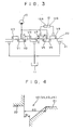
- the rotary control valve 14, shown as an enlarged development view in FIG. 3, is composed of a valve shaft 21 coupled to the steering wheel 13 for rotation therewith, a valve body 22 arranged to surround the valve shaft 21 in a coaxial relationship therewith, a torsion bar (not shown) connecting the valve shaft 21 to the valve body 22 in the manner that they are relatively rotatable within a limited angle, and a valve housing (not shown) receiving the above-mentioned components therein.
- the valve body 22 is mechanically connected to a steering linkage to which hydraulic force generated by the power cylinder 12 is applied.
- Each of the outer surface of the valve shaft 21 and the inner surface of the valve body 22 is provided with a plurality of axial slots, which are formed at predetermined intervals in the circumferential direction.
- two kinds of control portions i.e., first control portion 23 and second control portion 24 are formed between the valve shaft 15 and the valve body 16 alternately at intervals of 90 degrees in the circumferential direction so as to control the flow of pressurized fluid.
- the first control portion 23 is composed of a first bridge circuit C1 having four fluid paths L1, L2, L3 and L4 which are connected to the pump 10 and the reservoir 11, and four variable orifices V1, V2, V3 and V4 are disposed in the middle of the fluid paths L1, L2, L3 and L4, respectively.
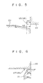
- Each of the variable orifices V1, V2, V3 and V4 is of center-open type, and the initial state (neutral state) of which is shown in FIG. 4.
- Each of the variable orifices V1, V2, V3 and V4 has such a characteristic that the opening area of each orifice changes as illustrated by the line A1 in FIG. 7 with relative rotation (valve rotational angle) between the valve shaft 21 and valve body 22.
- the second control portion 24 is composed of a second bridge circuit C2 having four fluid paths L5, L6, L7 and L8 which are connected to the pump 10, both fluid chambers 12A and 12B of the power cylinder 12 and the reservoir 11, and four variable orifices V5, V6, V7 and V8 are disposed in the middle of the fluid paths L5, L6, L7 and L8, respectively.
- Each of the variable orifices V5 and V6 communicating with the pump 10 is of semi-center-open type, and the initial state of which is shown in FIG. 5.
- Each of the variable orifices V7 and V8 communicating with the reservoir 11 is of center-closed type, the initial state of which is shown in FIG. 6.
- variable orifices V5 and V6 has such a characteristic that the opening area of each orifice changes as illustrated by the line A2 in FIG. 7 with the relative rotation between the valve shaft 21 and valve body 22.
- variable orifices V7 and V8 has such a characteristic that the opening area of each orifice changes as illustrated by the line A3 in FIG. 7 with the relative rotation between the valve shaft 21 and valve body 22.
- numeral 30 indicates a supply hose for supplying pressurized fluid to the rotary control valve 14.
- pressurized fluid discharged from the pump 10 to the rotary control valve 14 is controlled by the metering orifice 17 and the flow control valve 18 to substantially constant flow rate and pressurized fluid at such flow rate is supplied to the first and second control portion 23 and 24.
- variable orifices V2 and V3 of the first control portion 23 increase while the opening areas of the remaining variable orifices V1 and V4 decrease.
- the pressure of the fluid discharged from the pump 10, i.e., the supply pressure to the rotary control valve 14 gradually increases.
- the pressures in the fluid chambers 12A and 12B of the power cylinder 12 are gradually increased, but the differential pressure therebetween is maintained to be zero until the relative rotational angle of the rotary control valve 14 reaches ⁇ 1, because the center-closed variable orifices V7 and V8 of the second control portion 24 remain in the closed state until the relative rotational angle of the rotary control valve 14 reaches ⁇ 1. Accordingly, within the neutral zone that the relative rotational angle of the rotary control valve 14 is smaller than ⁇ 1, the differential pressure between the fluid chambers 12A and 12B of the power cylinder 12 is prevented from increasing, as illustrated by the solid curved line in FIG. 8. Namely, within the neutral zone, the steering feeling is the same as that in a manual (or no power assisted) steering apparatus, and the rigidity against rotation of the steering wheel 13 at around the neutral position can be increased.
- the pressure in the fluid chamber 12A depends on the opening areas of the variable orifices V5 and V7 of the second control portion 24, while that in the fluid chamber 12B depends on the opening areas of the variable orifices V6 of the second control portion 24.
- the differential pressure across the power cylinder 12 is maintained to be extremely low or substantially zero when the steering wheel 13 is at around the neutral position. Therefore, at around the neutral position of the steering wheel 13, the steering feeling is the same as that in the manual steering apparatus, so that the driver can definitely feel the neutral position of the steering wheel, because the rigidity of the steering wheel 13, i.e., the resistance to turn the same is enhanced at around the neutral position. This also enables the driver to feel the beginning of power assist when the steering wheel 13 is turned in either direction beyond a certain angle ⁇ 1 from the neutral position.
- the two drain paths L7 and L8 of the second control portion 24 communicating with the reservoir 11 are closed by the center-closed variable orifices V7 and V8, while one of the fluid chambers 12A and 12B of the power cylinder 12 is brought into communication with the other thereof through the semi-center-open variable orifices V5 and V6 of the second control portion 24. Therefore, the pressurized fluid in one of the chambers 12A and 12B is smoothly supplied to the other thereof, so that the returning of the steering wheel 13 can be improved.
- variable orifices V5 and V6 are formed as of center-open type which have the same configuration as those V1-V4. Namely, each of the variable orifices V5 and V6 has its configuration as shown in FIG. 10. Therefore, as shown in FIG. 11, each of the variable orifices V5 and V6 is closed in the same rate as those V1-V4 as the relative valve rotation advances in either direction.
- variable orifices V5 and V6 are configured as of center-open type, the pressure increase exerted by the first control portion 23 is immediately applied to the power cylinder 12. This causes the differential pressure across the power cylinder 12 to increase faster than as is done in the first embodiment as the relative valve rotation advances in either direction, as indicated by the phantom curved line in FIG. 8.
Landscapes
- Engineering & Computer Science (AREA)
- Chemical & Material Sciences (AREA)
- Combustion & Propulsion (AREA)
- Transportation (AREA)
- Mechanical Engineering (AREA)
- Power Steering Mechanism (AREA)
- Steering Control In Accordance With Driving Conditions (AREA)
Claims (5)
- Appareil de direction assistée ayant une source (10) de fluide pour la fourniture d'un fluide sous pression, un cylindre moteur (12), une valve (14) de commande qui réagit à la manoeuvre d'un volant de direction (13) en alimentant ledit cylindre de travail (12) en fluide sous pression à partir de ladite source (10) de fluide, et un réservoir (11), ladite valve (14) de commande comportant :une première partie de commande (23) destinée à commander l'écoulement de fluide sous pression de ladite source (10) de fluide jusqu'audit réservoir (11), ladite première partie de commande (23) ayant au moins un trajet (L1, L3 ; L2, L4) reliant ladite source (10) de fluide et ledit réservoir (11) ; etune seconde partie de commande (24) destinée à commander l'écoulement de fluide sous pression de ladite source de fluide (10) jusqu'audit cylindre (12) de travail, ladite seconde partie de commande (24) ayant deux trajets d'alimentation (L5, L6) faisant communiquer ladite source de fluide (10), respectivement, avec deux chambres à fluide (12A, 12B) dudit cylindre (12) de travail et deux trajets (L7, L8) de vidange faisant, respectivement, communiquer les chambres (12A, 12B) dudit cylindre de travail (12) avec ledit réservoir (11),
dans lequel chacun desdits deux trajets d'alimentation (L5, L6) est formé de façon à comporter un orifice variable (V5, V6) du type à centre ouvert qui est ouvert lorsque ladite valve de commande (14) est dans l'état neutre,
caractérisé en ce que chacun desdits deux trajets de vidange (L7, L8) est formé de façon à présenter un orifice variable (V7, V8) du type à centre fermé qui est fermé lorsque ladite valve de commande (14) est dans l'état neutre et en ce que ledit, au moins un, trajet (L1, L3 ; L2, L4) de ladite première partie de commande (23) est formé de façon à présenter au moins un orifice variable (V1, V3 ; V2, V4) du type à centre ouvert, ledit trajet (L1, L3 ; L2, L4) étant ouvert lorsque ladite valve de commande (14) est dans l'état neutre. - Appareil de direction assistée selon la revendication 1, caractérisé en ce que lesdites chambres à fluide (12A, 12B) dudit cylindre de travail (12) communiquent entre elles par l'intermédiaire desdits deux trajets d'alimentation (L5, L6) de ladite seconde partie de commande (24) lorsque ladite valve de commande (14) est dans l'état neutre.
- Appareil de direction assistée selon la revendication 1 ou 2, caractérisé en ce que chacun desdits orifices variables (V5, V6) formés dans lesdits deux trajets d'alimentation (L5, L6) de ladite seconde partie de commande (24) est du type à centre semi-ouvert dans la section d'ouverture est plus petite que celle du type à centre ouvert lorsque ladite valve de commande (14) est dans l'état neutre.
- Appareil de direction assistée selon l'une des revendications 1 à 3, caractérisé en ce que ladite première partie de commande (23) forme deux trajets d'alimentation (L1, L2) communiquant avec ladite source de fluide (10) et deux trajets de vidange (L3, L4) communiquant avec ledit réservoir (11), et en ce que chacun desdits trajets (L1, L2, L3, L4) de ladite première partie de commande (23) est formé de façon à comporter un orifice variable (V1, V2, V3, V4) du type à centre ouvert qui s'ouvre lorsque ladite valve de commande (14) est dans l'état neutre.
- Appareil de direction assistée selon l'une des revendications 1 à 4, caractérisé en ce que ledit appareil de direction assistée comportant en outre :un orifice de dosage (17) placé dans un passage d'alimentation (16) faisant communiquer ladite source de fluide (11) avec ladite valve de commande (14) ; etun moyen (18) de réglage de débit d'écoulement agissant en réponse à une pression différentielle à travers ledit orifice de dosage (17) pour maintenir sensiblement constant un débit d'écoulement de fluide sous pression fourni à ladite valve de commande (14) depuis ladite source de fluide (11).
Applications Claiming Priority (2)
| Application Number | Priority Date | Filing Date | Title |
|---|---|---|---|
| JP283337/93 | 1993-11-12 | ||
| JP5283337A JP2932907B2 (ja) | 1993-11-12 | 1993-11-12 | 動力舵取装置 |
Publications (3)
| Publication Number | Publication Date |
|---|---|
| EP0653342A2 EP0653342A2 (fr) | 1995-05-17 |
| EP0653342A3 EP0653342A3 (fr) | 1996-08-14 |
| EP0653342B1 true EP0653342B1 (fr) | 1998-06-03 |
Family
ID=17664177
Family Applications (1)
| Application Number | Title | Priority Date | Filing Date |
|---|---|---|---|
| EP94117861A Expired - Lifetime EP0653342B1 (fr) | 1993-11-12 | 1994-11-11 | Direction à assistance hydraulique |
Country Status (4)
| Country | Link |
|---|---|
| US (1) | US5638912A (fr) |
| EP (1) | EP0653342B1 (fr) |
| JP (1) | JP2932907B2 (fr) |
| DE (1) | DE69410750T2 (fr) |
Families Citing this family (12)
| Publication number | Priority date | Publication date | Assignee | Title |
|---|---|---|---|---|
| JP3368666B2 (ja) * | 1994-06-14 | 2003-01-20 | 豊田工機株式会社 | 動力舵取装置 |
| JP3240866B2 (ja) * | 1995-01-19 | 2001-12-25 | 豊田工機株式会社 | 動力舵取装置 |
| DE19705382A1 (de) * | 1996-02-13 | 1997-08-14 | Unisia Jecs Corp | Hilfskrafteinheit für eine Lenkanlage |
| JPH09249142A (ja) * | 1996-03-14 | 1997-09-22 | Kayaba Ind Co Ltd | パワーステアリング装置 |
| JP3463453B2 (ja) * | 1996-03-28 | 2003-11-05 | 豊田工機株式会社 | 動力舵取装置 |
| JPH1045008A (ja) * | 1996-07-31 | 1998-02-17 | Toyoda Mach Works Ltd | 動力舵取装置 |
| JP2001180508A (ja) * | 1999-12-27 | 2001-07-03 | Toyota Autom Loom Works Ltd | パワーステアリングバルブ |
| AU2003265212A1 (en) * | 2002-05-03 | 2003-11-17 | Trw Automotive U.S. Llc | Power steering control valve |
| US7152627B2 (en) * | 2004-04-05 | 2006-12-26 | R. H. Sheppard Co., Inc. | Control valve for a hydraulic power steering system |
| US7487856B2 (en) * | 2006-08-30 | 2009-02-10 | Fluid Routing Solutions, Inc. | Electrically actuated, hydraulic power steering system |
| EP2610142B1 (fr) | 2011-12-27 | 2014-03-05 | Sauer-Danfoss ApS | Dispositif de direction hydraulique |
| EP2610137B1 (fr) * | 2011-12-28 | 2014-03-05 | Sauer-Danfoss ApS | Dispositif de direction hydraulique |
Family Cites Families (9)
| Publication number | Priority date | Publication date | Assignee | Title |
|---|---|---|---|---|
| US4164892A (en) * | 1976-12-22 | 1979-08-21 | Trw Inc. | Control apparatus |
| EP0083490A3 (fr) * | 1981-12-31 | 1984-05-02 | Adwest Engineering Limited | Soupape rotative pour un dispositif de direction assistée |
| JPS6015265A (ja) * | 1983-07-04 | 1985-01-25 | Toyoda Mach Works Ltd | サ−ボバルブ |
| JP2855446B2 (ja) * | 1989-05-22 | 1999-02-10 | カヤバ工業株式会社 | パワーステアリング装置 |
| JPH0542880A (ja) * | 1991-08-09 | 1993-02-23 | Kayaba Ind Co Ltd | パワーステアリングの操舵力制御装置 |
| JPH05310136A (ja) * | 1992-05-01 | 1993-11-22 | Kayaba Ind Co Ltd | パワーステアリング装置 |
| JP3353275B2 (ja) * | 1992-10-22 | 2002-12-03 | 豊田工機株式会社 | 動力舵取装置 |
| DE69319990T2 (de) * | 1992-10-22 | 1998-12-10 | Toyoda Koki K.K., Kariya, Aichi | Hydraulische Servolenkung |
| JP3353276B2 (ja) * | 1992-10-22 | 2002-12-03 | 豊田工機株式会社 | 動力舵取装置 |
-
1993
- 1993-11-12 JP JP5283337A patent/JP2932907B2/ja not_active Expired - Fee Related
-
1994
- 1994-11-10 US US08/339,229 patent/US5638912A/en not_active Expired - Lifetime
- 1994-11-11 EP EP94117861A patent/EP0653342B1/fr not_active Expired - Lifetime
- 1994-11-11 DE DE69410750T patent/DE69410750T2/de not_active Expired - Fee Related
Also Published As
| Publication number | Publication date |
|---|---|
| EP0653342A3 (fr) | 1996-08-14 |
| EP0653342A2 (fr) | 1995-05-17 |
| DE69410750T2 (de) | 1998-12-03 |
| US5638912A (en) | 1997-06-17 |
| JPH07132842A (ja) | 1995-05-23 |
| DE69410750D1 (de) | 1998-07-09 |
| JP2932907B2 (ja) | 1999-08-09 |
Similar Documents
| Publication | Publication Date | Title |
|---|---|---|
| EP0594137B1 (fr) | Direction hydraulique assistée | |
| US5439070A (en) | Hydraulic power steering apparatus | |
| US5638912A (en) | Hydraulic power steering apparatus | |
| US4410058A (en) | Vehicle steering apparatus | |
| US5184693A (en) | Vehicle hydraulic power steering system | |
| GB2311047A (en) | Flow controlling apparatus for power steering system | |
| EP0658468B1 (fr) | Direction hydraulique assistée | |
| EP0727342B1 (fr) | Direction assistée | |
| US4905784A (en) | Power-assisted steering system for automotive vehicle | |
| US5207780A (en) | Hydraulic valve device for automotive power steering gear | |
| EP0911245B1 (fr) | Système de direction assistée | |
| EP0687616B1 (fr) | Direction assistée | |
| US5778756A (en) | Hydraulic power steering apparatus | |
| US6216815B1 (en) | Power steering apparatus | |
| US6035760A (en) | Power steering system | |
| JP3353275B2 (ja) | 動力舵取装置 | |
| JP3248464B2 (ja) | 動力舵取装置 | |
| JP3057409B2 (ja) | 車速感応式パワーステアリング装置 | |
| JPH0619426Y2 (ja) | 動力舵取装置の操舵力制御装置 | |
| JPH0619420Y2 (ja) | 動力舵取装置の操舵力制御装置 | |
| JPH08127354A (ja) | パワーステアリング装置 | |
| JPH05338545A (ja) | パワーステアリング装置 | |
| JPH0999851A (ja) | 動力舵取装置 | |
| JPH06344931A (ja) | 動力舵取装置 | |
| JPH0834361A (ja) | パワーステアリング装置 |
Legal Events
| Date | Code | Title | Description |
|---|---|---|---|
| PUAI | Public reference made under article 153(3) epc to a published international application that has entered the european phase |
Free format text: ORIGINAL CODE: 0009012 |
|
| AK | Designated contracting states |
Kind code of ref document: A2 Designated state(s): DE FR GB |
|
| PUAL | Search report despatched |
Free format text: ORIGINAL CODE: 0009013 |
|
| AK | Designated contracting states |
Kind code of ref document: A3 Designated state(s): DE FR GB |
|
| 17P | Request for examination filed |
Effective date: 19970109 |
|
| 17Q | First examination report despatched |
Effective date: 19970221 |
|
| GRAG | Despatch of communication of intention to grant |
Free format text: ORIGINAL CODE: EPIDOS AGRA |
|
| GRAG | Despatch of communication of intention to grant |
Free format text: ORIGINAL CODE: EPIDOS AGRA |
|
| GRAH | Despatch of communication of intention to grant a patent |
Free format text: ORIGINAL CODE: EPIDOS IGRA |
|
| GRAH | Despatch of communication of intention to grant a patent |
Free format text: ORIGINAL CODE: EPIDOS IGRA |
|
| GRAA | (expected) grant |
Free format text: ORIGINAL CODE: 0009210 |
|
| AK | Designated contracting states |
Kind code of ref document: B1 Designated state(s): DE FR GB |
|
| REF | Corresponds to: |
Ref document number: 69410750 Country of ref document: DE Date of ref document: 19980709 |
|
| ET | Fr: translation filed | ||
| PLBE | No opposition filed within time limit |
Free format text: ORIGINAL CODE: 0009261 |
|
| STAA | Information on the status of an ep patent application or granted ep patent |
Free format text: STATUS: NO OPPOSITION FILED WITHIN TIME LIMIT |
|
| 26N | No opposition filed | ||
| REG | Reference to a national code |
Ref country code: GB Ref legal event code: IF02 |
|
| PGFP | Annual fee paid to national office [announced via postgrant information from national office to epo] |
Ref country code: GB Payment date: 20071107 Year of fee payment: 14 |
|
| PGFP | Annual fee paid to national office [announced via postgrant information from national office to epo] |
Ref country code: DE Payment date: 20081107 Year of fee payment: 15 |
|
| PGFP | Annual fee paid to national office [announced via postgrant information from national office to epo] |
Ref country code: FR Payment date: 20081112 Year of fee payment: 15 |
|
| GBPC | Gb: european patent ceased through non-payment of renewal fee |
Effective date: 20081111 |
|
| PG25 | Lapsed in a contracting state [announced via postgrant information from national office to epo] |
Ref country code: GB Free format text: LAPSE BECAUSE OF NON-PAYMENT OF DUE FEES Effective date: 20081111 |
|
| REG | Reference to a national code |
Ref country code: FR Ref legal event code: ST Effective date: 20100730 |
|
| PG25 | Lapsed in a contracting state [announced via postgrant information from national office to epo] |
Ref country code: FR Free format text: LAPSE BECAUSE OF NON-PAYMENT OF DUE FEES Effective date: 20091130 |
|
| PG25 | Lapsed in a contracting state [announced via postgrant information from national office to epo] |
Ref country code: DE Free format text: LAPSE BECAUSE OF NON-PAYMENT OF DUE FEES Effective date: 20100601 |