EP0653348A1 - Bateau pliable - Google Patents
Bateau pliable Download PDFInfo
- Publication number
- EP0653348A1 EP0653348A1 EP94117427A EP94117427A EP0653348A1 EP 0653348 A1 EP0653348 A1 EP 0653348A1 EP 94117427 A EP94117427 A EP 94117427A EP 94117427 A EP94117427 A EP 94117427A EP 0653348 A1 EP0653348 A1 EP 0653348A1
- Authority
- EP
- European Patent Office
- Prior art keywords
- boat
- line
- boat bottom
- flat plate
- collapsible
- Prior art date
- Legal status (The legal status is an assumption and is not a legal conclusion. Google has not performed a legal analysis and makes no representation as to the accuracy of the status listed.)
- Withdrawn
Links
Images






Classifications
-
- B—PERFORMING OPERATIONS; TRANSPORTING
- B63—SHIPS OR OTHER WATERBORNE VESSELS; RELATED EQUIPMENT
- B63B—SHIPS OR OTHER WATERBORNE VESSELS; EQUIPMENT FOR SHIPPING
- B63B7/00—Collapsible, foldable, inflatable or like vessels
- B63B7/06—Collapsible, foldable, inflatable or like vessels having parts of non-rigid material
- B63B7/08—Inflatable
- B63B7/082—Inflatable having parts of rigid material
-
- B—PERFORMING OPERATIONS; TRANSPORTING
- B63—SHIPS OR OTHER WATERBORNE VESSELS; RELATED EQUIPMENT
- B63B—SHIPS OR OTHER WATERBORNE VESSELS; EQUIPMENT FOR SHIPPING
- B63B3/00—Hulls characterised by their structure or component parts
- B63B3/14—Hull parts
- B63B3/16—Shells
- B63B3/18—Shells characterised by being formed predominantly of parts that may be developed into plane surfaces
-
- B—PERFORMING OPERATIONS; TRANSPORTING
- B63—SHIPS OR OTHER WATERBORNE VESSELS; RELATED EQUIPMENT
- B63B—SHIPS OR OTHER WATERBORNE VESSELS; EQUIPMENT FOR SHIPPING
- B63B7/00—Collapsible, foldable, inflatable or like vessels
- B63B2007/003—Collapsible, foldable, inflatable or like vessels with foldable members
Definitions
- the present invention relates to a collapsible boat in which a boat bottom is installed at a buoyancy body so as to be attachable to and removable from the buoyancy body.
- a collapsible boat 100 is formed by a hull outer board 102, a plurality of reinforcing frames 104, 106 and the like.
- An unillustrated bow reinforcing frame is mounted to the bow side of the hull outer board 102, and a cover 108 is fit to the top end surface of the unillustrated bow reinforcing frame so as to be attached thereto.
- a rear portion reinforcing frame 104 is mounted to the stern side of the hull outer board 102.
- a front portion reinforcing frame 106 is mounted between the bow reinforcing frame and the rear portion reinforcing frame 104.
- Stiffeners 110, 112 for reinforcement and buoyancy are adhered to the respective sides of the hull outer board 102.
- the hull outer board 102 is divided into a plurality of outer board pieces (FRP boards) 102A.
- the outer board pieces 102A are joined by waterproof synthetic fiber fabric (not illustrated) .
- the synthetic resin fabric is coated with a synthetic rubber solution, and adheres and is made waterproof due to the synthetic rubber solution drying.
- the collapsible boat 100 disclosed in the above-mentioned publication is to be used, after the hull outer board 102 is bent into a hull shape as illustrated in Fig. 19, the rear portion reinforcing frame 104, the front portion reinforcing frame 106 and the like are mounted.
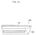
- the collapsible boat 100 is to be transported, as illustrated in Fig. 21, after the rear portion reinforcing frame 104, the front portion reinforcing frame 106 and the like are removed, the hull outer board 102 is folded at the seams of the respective hull outer board pieces 102A.
- the hull outer board 102 is merely structured as a set of a plurality of planar boards. Accordingly, the assembled collapsible boat 100 is also structured as a set of planes. As a result, this structure does not allow for a curved configuration which is superior with respect to ability to ride over waves and seaworthiness, and does not sufficiently address the demand for an improvement of these properties.
- an object of the present invention is to provide a collapsible boat in which ability to ride over waves and seaworthiness are improved.
- the collapsible boat of the present invention includes: a boat bottom, the boat bottom being fabricated by curving a thin, flat plate into a quadric surface such that a predetermined keel line, a predetermined chine line, and a predetermined stern line are included on or above the flat plate; dividing a portion of the flat plate, which portion is surrounded by the keel line, the chine line and the stern line, by a plurality of straight lines; and connecting a plurality of flat plate pieces together such that the flat plate pieces are bendable, the flat plate pieces being formed in configurations which respectively match divided shapes; and a buoyancy body, the boat bottom being installed at a bottom portion of the buoyancy body so as to be attachable to and removable from the buoyancy body.
- a plurality of belt members and a plurality of stopper members may be provided at the boat bottom.
- a floor member which is foldable and attachable to and removable from a bottom portion of the boat bottom, may be fixed to the bottom portion of the boat bottom by the belt members and stopper members.
- a thin, flat plate is curved into a quadric surface such that a predetermined keel line, chine line and stern line are included on or above the flat plate.
- a keel line, chine line and stern line which are excellent with respect to ability to ride over waves and seaworthiness are first determined, and a thin, flat plate is curved into a quadric surface such that these three determined lines are included on or above the flat plate.
- a plurality of straight lines are drawn on the portion of the flat plate which is surrounded by the three lines, so as to divide the portion into smaller regions.
- the flat plate is unfolded so as to be made planar, and serves as a cutting model.
- flat plate pieces of configurations which match the divided shapes of the cutting model are fabricated. Adjacent flat plate pieces are connected at the keel line or at the straight lines so as to be bendabie. In this way, the boat bottom is formed.
- the boat bottom When the collapsible boat is to be used, the boat bottom is unfolded so that the determined keel line, chine line and stern line reappear. Accordingly, if the boat bottom in this state is installed at the buoyancy body, a boat having superior ability to ride over waves and excellent seaworthiness is obtained. Further, because the boat bottom formed by the above-described processes has a three-dimensional shell construction, sufficient hull strength is obtained.
- the boat bottom is separated from the buoyancy body.
- the boat bottom is folded around the keel line. In this way, the width of the boat bottom becomes about one-half of its previous width. Further, the buoyancy body can be folded in a desired shape. Accordingly, the collapsible boat can be packed compactly, and a passenger car is sufficient to transport the collapsible boat.
- the hull strength can be further improved.
- the floor member is folded after being separated from the bottom portion of the boat bottom, the floor member is made compact in the same way as the boat bottom.
- the boat bottom of the above-described collapsible boat relating to the present invention which boat bottom is installed so as to be attachable to and removable from the buoyancy body, is formed in the following way.
- a thin, flat plate is curved into a quadric surface such that a predetermined keel line, chine line and stern line are included on or above the flat plate.
- the portion of the flat plate surrounded by the three lines is divided by a plurality of straight lines.
- a plurality of flat plate pieces, which are formed in configurations which match the divided shapes, are connected together so as to be bendable. Therefore, the present invention provides superior effects in that ability to ride over waves and seaworthiness can be improved.
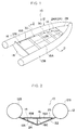
- Fig. 1 is a perspective view of a collapsible boat relating to the present embodiment.
- Fig. 2 is a cross-sectional view taken along line 2-2 of Fig. 1.
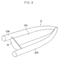
- Fig. 3 is a perspective view of a boat main body which is illustrated in Fig. 1 and in which a boat bottom and a transom board are attached to a buoyancy body.
- Fig. 4A is a side view of a floor member of Fig. 1.
- Fig. 4B is a plan view of the floor member of Fig. 1.
- Fig. 4C is a front view of the floor member of Fig. 1.
- Fig. 5 is a perspective view of the floor member illustrated in Figs. 4A through 4C.
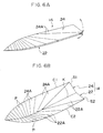
- Fig. 6A is a perspective view of a boat bottom in a folded state.
- Fig. 6B is a perspective view of the boat bottom in an unfolded state.
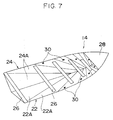
- Fig. 7 is a perspective view illustrating the unfolded state of the boat bottom including belts and the like.
- Fig. 8 is a perspective view illustrating a state in which the floor member is attached to the boat bottom illustrated in Fig. 7.
- Fig. 9 is a perspective view illustrating a jig for fabricating the boat bottom.
- Fig. 10 is a perspective view illustrating a state in which a flat plate is spread at the jig illustrated in Fig. 9.
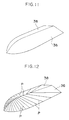
- Fig. 11 is a perspective view illustrating a state in which an original pattern of a cutting pattern is spread at the jig.
- Fig. 12 is a perspective view illustrating a state in which a plurality of straight lines are drawn on the original pattern of Fig. 11.
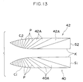
- Fig. 13 is a plan view illustrating a cutting pattern which has been removed from the jig.
- Fig. 14 is a perspective view illustrating a jig relating to a variant example.
- Fig. 15 is a perspective view illustrating a state in which an original pattern has been spread at a jig.
- Fig. 16 is a perspective view illustrating a state in which a plurality of straight lines are drawn on the original pattern of Fig. 15.
- Fig. 17 is a perspective view illustrating a jig, which is a companion jig of the jig illustrated in Fig. 17, and an original pattern.
- Fig. 18 is a perspective view illustrating a state in which both jigs are set together and the bottom portion pieces are spread.
- Fig. 19 is a plan view illustrating a collapsible boat relating to a conventional example.
- Fig. 20 is a plan view illustrating a hull outer board (boat bottom) of the boat of Fig. 19.
- Fig. 21 is a plan view illustrating a state in which the boat of Fig. 19 is folded.
- Fig. 1 is an external perspective view of a collapsible boat 10 relating to the present embodiment.
- Fig. 2 is a sectional view taken along line 2-2 of Fig. 1.
- the boat 10 is structured by a buoyancy body 12, a boat bottom 14 which is installed at the buoyancy body 12, and a floor member 16 which is fixed to the boat bottom 14.
- the buoyancy body 12, the floor member 16 and the boat bottom 14 will be described hereinafter in that order.
- the buoyancy body 12 is made of rubber, and includes a bottom portion 12A and side portions 12B. Each side portion 12B is formed as a hollow cylinder and is inflated by air or the like being injected into the hollow portion thereof. Further, a transom board 18, which is a hard board, is fixed to the stern side of the buoyancy body 12. An unillustrated outboard may be mounted to the transom board 18. When the boat bottom 14 and the transom board 18 are attached to the buoyancy body 12, the resultant structure is referred to as the "boat main body".
- Figs. 4A through 4C are three surface views of the floor member 16, and Fig. 5 is a perspective view thereof.
- the floor member 16 is formed of three board members: floorboards 16A, 16B and a keel reinforcing board 16C.
- the floorboards 16A, 16B are symmetrical to the left and right of the keel reinforcing board 16C, and taper toward the bow.
- the keel reinforcing board 16C is positioned on a keel line K (see Fig. 6B) which will be described later.
- the floorboards 16A, 16B and the keel reinforcing board 16C are connected by hinges 20.
- the floor member 16 can be folded into a three-layer-stack by the floorboard 16B and the keel reinforcing board 16C being pivoted around the hinges 20 in the direction of the arrow in Fig. 4C such that the floorboards 16A, 16B and the keel reinforcing board 16C are stacked one on top of another.
- the boat bottom 14 is formed of, for example, FRP and is structured by bottom portions 22, 24. Steel, aluminum alloy, or wooden boards may be used for the boat bottom 14 provided that the strength and weight required for the seaworthiness of the boat 10 fall within an allowed range.
- the bottom portions 22, 24 are symmetrical to the left and right of the keel line K.
- the boat bottom 14 tapers toward the bow.
- Each of the bottom portions 22, 24 is formed as a set of a plurality of panel-shaped bottom portion pieces 22A, 24A, respectively, which are each formed in a predetermined configuration.
- each bottom portion 22, 24 is divided by a plurality of straight lines P into a plurality of the bottom portion pieces 22A, 24A, respectively.
- Each of the straight lines P is a straight line having one end at the keel line K and the other end at a chine line C1 (or a chine line C2) or at the intersection of the chine line C1 and a stern line S1 (or the intersection of the chine line C2 and a stern line S2).
- Adjacent bottom portion pieces 22A, 24A are connected at the straight lines P and at the keel line K so as to be bendable.
- both of the bottom portions 22, 24 are planar.
- the boat bottom 14 is placed in the unfolded state illustrated in Fig. 6B.
- both of the bottom portions 22, 24 are shaped as quadric surfaces which gradually curve toward the bow.
- the pair of stern lines S1, S2 intersect and form a V-shape at the stern side of the boat bottom 14.
- a plurality of belts 26 are attached at predetermined intervals to the bottom portions 22, 24 of the boat bottom 14.
- the belts 26 are formed of a strong, flexible material which, although flexible, is difficult to stretch, such as nylon or the like. More specifically, the belt 26 is member in which canvas and synthetic rubber, or the like, are adhered together in a sheet-like form. Further, a sheet member 28, which is made of the same material as the belts 26, is adhered to the bow side of the boat bottom 14. The ends of the sheet member 28 are folded over onto the reverse surfaces of the bottom portions 22, 24. Accordingly, the boat bottom 14 can be unfolded until the belts 26 and the sheet member 28 are stretched to a predetermined tension.
- the belts 26 and the sheet member 28 prevent the pair of chine lines C1 C2 of the boat bottom 14 from opening beyond the intended positions.
- stoppers 30 are provided at predetermined positions of the surfaces of the bottom portions 22, 24 of the boat bottom 14 (between the points where adjacent belts 26 are attached).
- a jig 32 illustrated in Fig. 9 is used.
- the jig 32 is formed by a chine line forming portion 32A, a keel line forming portion 32B, and a stern line forming portion 32C.
- the chine line forming portion 32A is shaped as a rectangular board which tapers at one end thereof.
- the keel line forming portion 32B is a strip-like board which rises up at the center of the chine line forming portion 32A.
- the stern line forming portion 32C is an isosceles triangle shaped board which rises at the stern side of the keel line forming portion 32B.
- the peripheral edge line of the chine line forming portion 32A determines the chine lines C1, C2
- the upper edge line of the keel line forming portion 32B determines the keel line K
- the upper edge line of the stern line forming portion 32C determines the stern lines S1, S2. It is to be noted that the configuration of the jig 32 may be changed appropriately in accordance with the intended ability to ride over waves and seaworthiness.
- a thin, rectangular, flat plate 34 such as a steel plate or the like, is spread at one surface of the jig 32.
- the peripheral edge of the chine line forming portion 32A, the upper edge of the keel line forming portion 32B and the upper edge of the stern line forming portion 32C all contact the flat plate 34 without any gaps therebetween.
- the flat plate 34 is a quadric surface.
- the peripheral edge of the chine line Forming portion 32A, the upper edge of the keel line Forming portion 32B and the upper edge of the stern line forming portion 32C are traced so that the intended chine line C1, keel line K and stern line S1 are copied onto the flat plate 34.
- the flat plate 34 which was spread in a quadric surface like form, is removed from the jig 32 and is returned to its original planar shape. Subsequently, the flat plate 34 is cut along the copied chine line C1, keel line K and stern line S1. Following the same processes, another flat plate 34 is spread at the other surface of the jig 32.
- the intended chine line C2, keel line K and stern line S2 are traced onto the flat plate 34 which is then cut.
- original patterns 36, 38 obtained in this way are again spread on the jig 32. Regions of the surfaces of the original patterns 36, 38 at which straight lines can be drawn are found, and a plurality of the straight lines P are drawn as illustrated in Fig. 12. Then, when the patterns 36, 38 are removed from the jig 32 and are unfolded into planar shapes, cutting patterns 40, 42, which are respectively a set of a plurality of divided surfaces 40A, 42A as illustrated in Fig. 13, are obtained.
- the bottom portion pieces 22A, 24A of configurations matching the divided surfaces 40A, 42A of the resultant cutting patterns 40, 42, are fabricated.
- the bottom portion pieces 22A, 24A are again spread on the jig 32, and adjacent bottom portion pieces 22A, 24A are bendably connected by welding, adhesion, or the like, in accordance with the plurality of straight lines P and the keel line K.
- the boat bottom 14 illustrated in Figs. 6A, 6B is thereby obtained.
- the boat bottom 14 which is folded in a two-layer-stack (the state shown in Fig. 6A) is unfolded about the keel line K so as to be set in the state illustrated in Fig. 6B (more correctly, the state illustrated in Fig. 7) .
- the intended keel line K, chine lines C1, C2, and stern lines S1, S2 reemerge.
- the floor member 16 which had been folded into a three-layer-stack, is unfolded so as to be placed in the state illustrated in Fig. 5.
- the floor member 16 is inserted into the boat bottom 14 from the stern side, and is fixed by the plurality of belts 26, the sheet member 28 and the stoppers 30.
- the keel reinforcing board 16C of the floor member 16 is positioned above the keel line K of the boat bottom 14. Further, movement of the boat bottom 14 in the opening directions is regulated by the belts 26 and the sheet member 28, and movement of the boat bottom 14 in the closing directions is regulated by the stoppers 30.
- the boat bottom 14 to which the floor member 16 is fixed is installed at the buoyancy body 12.
- air or the like is not injected into the side portions 12B of the buoyancy body 12 in its unfolded state.
- air or the like is injected into the side portions 12B of the buoyancy body 12 so that the side portions 12B inflate. In this way, the assembly of the boat 10 is completed.
- the bottom portions 22, 24 of the boat bottom 14 are formed as sets of the plurality of bottom portion pieces 22A, 24A which form quadric surfaces when the boat bottom 14 is unfolded. Therefore, the intended keel line K, chine lines C1, C2, and stern lines S1, S2 can reappear. As a result, the ability to ride over waves and seaworthiness of the boat 10 can be improved.
- the boat bottom 14 can be folded compactly in a planar form, the boat 10 can be transported by a passenger car even if a large vehicle such as a trailer is not used. Therefore, the transportability of the boat 10 can be improved. Further, the work involved in loading and unloading the boat 10 is facilitated. Because the boat 10 can be folded up compactly, there is no need to store the boat 10 at a marina, and it can be stored at home. Therefore, the storability of the boat 10 can also be improved.
- the boat bottom 14 has a three-dimensional shell construction when unfolded, the hull strength of the boat 10 can be improved. Further, in the present embodiment, the belts 26, the sheet member 28 and the stoppers 30 are provided at the boat bottom 14 and are used to fix the floor member 16. Therefore, the hull strength can be improved even more. As a result, there is no need for a frame such as a keel or the like.
- the T-shaped floor member 16 is formed from three members (the floorboards 16A, 16B, and the keel reinforcing board 16C) .
- the present invention is not limited to the same, and any floor member which is shaped as a flat board and which is collapsible may be used.
- the jig 32 illustrated in Fig. 9 is used to fabricate the boat bottom 14.
- the present invention is not limited to the same, and the boat bottom 14 may be fabricated by using a jig 50 illustrated in Fig. 14.
- the structure of the jig 50 and processes for fabricating the boat bottom 14 by using the jig 50 will be briefly described.
- the jig 50 is formed as a hollow, substantial parallelepiped by front surface board 50A, rear surface board 50B, top surface board 50C, bottom surface board 50D, and side surface boards 50E, 50F. Further, a plurality of reinforcing boards 50G are disposed at predetermined intervals at the interior portion of the jig 50. The top surface board 50C, the front surface board 50A, and the side surface board 50E are cut in predetermined configurations. In this way, the chine line C2 is formed at the top surface board 50C, the keel line K is formed at the front surface board 50A, and the stern line S2 is formed at the side surface board 50E. It is to be noted that the jig 50 is used for one surface of the boat bottom 14.
- the fabrication processes are basically the same as those described previously.
- the flat plate 34 (not illustrated in the drawing) is spread on the jig 50 of Fig. 14, and the intended keel line K, chine line C2 and stern line S2 are copied.
- an original pattern 52 obtained from cutting along these lines is again spread on the jig 50 (see Fig. 15), and a plurality of straight lines P are drawn (see Fig. 16).
- a jig 56 is used for the remaining surface of the boat bottom 14.
- a plurality of straight lines P are drawn (see Fig. 17).
- the bottom portion pieces 22A, 24A which match the configurations of the divided surfaces of the cutting patterns obtained in this way, are fabricated, and are again spread on the jigs 50, 56 (see Fig. 18) . Thereafter, the adjacent bottom portion pieces 22A, 24A are connected together so as to be bendable.
- a collapsible boat including: a boat bottom, the boat bottom being fabricated by curving a thin, flat plate into a quadric surface such that a predetermined keel line, a predetermined chine line, and a predetermined stern line are included on or above the flat plate; dividing a portion of the flat plate, which portion is surrounded by the keel line, the chine line and the stern line, by a plurality of straight lines; and connecting a plurality of flat plate pieces together such that the flat plate pieces are bendable, the flat plate pieces being formed in configurations which respectively match divided shapes; and a buoyancy body, the boat bottom being installed at a bottom portion of the buoyancy body so as to be attachable to and removable from the buoyancy body.
- the collapsible boat has a curved configuration, sufficient strength, superior ability to ride over waves, and excellent seaworthiness.
Landscapes
- Chemical & Material Sciences (AREA)
- Engineering & Computer Science (AREA)
- Combustion & Propulsion (AREA)
- Mechanical Engineering (AREA)
- Ocean & Marine Engineering (AREA)
- Butt Welding And Welding Of Specific Article (AREA)
- Toys (AREA)
Applications Claiming Priority (2)
| Application Number | Priority Date | Filing Date | Title |
|---|---|---|---|
| JP5276376A JPH07125682A (ja) | 1993-11-05 | 1993-11-05 | 折り畳み式ボート |
| JP276376/93 | 1993-11-05 |
Publications (1)
| Publication Number | Publication Date |
|---|---|
| EP0653348A1 true EP0653348A1 (fr) | 1995-05-17 |
Family
ID=17568569
Family Applications (1)
| Application Number | Title | Priority Date | Filing Date |
|---|---|---|---|
| EP94117427A Withdrawn EP0653348A1 (fr) | 1993-11-05 | 1994-11-04 | Bateau pliable |
Country Status (2)
| Country | Link |
|---|---|
| EP (1) | EP0653348A1 (fr) |
| JP (1) | JPH07125682A (fr) |
Citations (6)
| Publication number | Priority date | Publication date | Assignee | Title |
|---|---|---|---|---|
| BE538498A (fr) * | ||||
| GB563324A (en) * | 1943-04-05 | 1944-08-09 | Modelcraft Ltd | Improvements in or relating to the construction of boats and jigs for use in the production thereof |
| US3108295A (en) * | 1958-10-06 | 1963-10-29 | Schor Herbert | Folding boat |
| FR2044479A1 (fr) * | 1966-11-26 | 1971-02-19 | Calverley Et Sons Ltd | Canot pliable |
| US4489668A (en) * | 1982-11-03 | 1984-12-25 | Cronin Thomas B | Hull construction |
| GB2259675A (en) * | 1991-09-20 | 1993-03-24 | John Edmonds Dowling | Folding boat |
-
1993
- 1993-11-05 JP JP5276376A patent/JPH07125682A/ja active Pending
-
1994
- 1994-11-04 EP EP94117427A patent/EP0653348A1/fr not_active Withdrawn
Patent Citations (6)
| Publication number | Priority date | Publication date | Assignee | Title |
|---|---|---|---|---|
| BE538498A (fr) * | ||||
| GB563324A (en) * | 1943-04-05 | 1944-08-09 | Modelcraft Ltd | Improvements in or relating to the construction of boats and jigs for use in the production thereof |
| US3108295A (en) * | 1958-10-06 | 1963-10-29 | Schor Herbert | Folding boat |
| FR2044479A1 (fr) * | 1966-11-26 | 1971-02-19 | Calverley Et Sons Ltd | Canot pliable |
| US4489668A (en) * | 1982-11-03 | 1984-12-25 | Cronin Thomas B | Hull construction |
| GB2259675A (en) * | 1991-09-20 | 1993-03-24 | John Edmonds Dowling | Folding boat |
Also Published As
| Publication number | Publication date |
|---|---|
| JPH07125682A (ja) | 1995-05-16 |
Similar Documents
| Publication | Publication Date | Title |
|---|---|---|
| EP3402717B1 (fr) | Structure d'embarcation gonflable et son procédé de fabrication | |
| US4807549A (en) | Collapsable elongated articles including sailboards and the like | |
| US10259535B2 (en) | Collapsible kayak with large cockpit | |
| EP0653348A1 (fr) | Bateau pliable | |
| US12252221B2 (en) | Collapsible watercraft | |
| US4282617A (en) | Boat hull, material or blank for a boat hull, and a method of producing a boat hull | |
| US3981035A (en) | Collapsible high speed boat | |
| US4489668A (en) | Hull construction | |
| US3228042A (en) | Collapsible floating body | |
| US5535697A (en) | Tube for a rubber boat and method of fabrication thereof | |
| JP2000025684A (ja) | エアーボート | |
| AU2023225053B2 (en) | Collapsible watercraft | |
| JPH0745422Y2 (ja) | ゴムボート | |
| US5088437A (en) | Boat hull construction method and product thereof | |
| JP2003226286A (ja) | 折り畳み式エアーボート | |
| JP2949406B2 (ja) | ボート | |
| JPH0958571A (ja) | エアーボート用底板 | |
| JPS62215702A (ja) | 展開浮橋 |
Legal Events
| Date | Code | Title | Description |
|---|---|---|---|
| PUAI | Public reference made under article 153(3) epc to a published international application that has entered the european phase |
Free format text: ORIGINAL CODE: 0009012 |
|
| 17P | Request for examination filed |
Effective date: 19941104 |
|
| AK | Designated contracting states |
Kind code of ref document: A1 Designated state(s): FR IT |
|
| 17Q | First examination report despatched |
Effective date: 19960529 |
|
| STAA | Information on the status of an ep patent application or granted ep patent |
Free format text: STATUS: THE APPLICATION IS DEEMED TO BE WITHDRAWN |
|
| 18D | Application deemed to be withdrawn |
Effective date: 19961010 |