EP0653367A1 - Système d'alignement de documents - Google Patents
Système d'alignement de documents Download PDFInfo
- Publication number
- EP0653367A1 EP0653367A1 EP94308336A EP94308336A EP0653367A1 EP 0653367 A1 EP0653367 A1 EP 0653367A1 EP 94308336 A EP94308336 A EP 94308336A EP 94308336 A EP94308336 A EP 94308336A EP 0653367 A1 EP0653367 A1 EP 0653367A1
- Authority
- EP
- European Patent Office
- Prior art keywords
- document
- alignment
- rolls
- drive
- feed path
- Prior art date
- Legal status (The legal status is an assumption and is not a legal conclusion. Google has not performed a legal analysis and makes no representation as to the accuracy of the status listed.)
- Granted
Links
- 230000002093 peripheral effect Effects 0.000 claims description 16
- 239000000463 material Substances 0.000 claims description 3
- 230000004044 response Effects 0.000 claims description 3
- 230000007246 mechanism Effects 0.000 description 26
- 230000003287 optical effect Effects 0.000 description 4
- 239000004033 plastic Substances 0.000 description 4
- 230000002441 reversible effect Effects 0.000 description 4
- 238000010276 construction Methods 0.000 description 3
- 238000000034 method Methods 0.000 description 3
- 230000006835 compression Effects 0.000 description 2
- 238000007906 compression Methods 0.000 description 2
- 230000009471 action Effects 0.000 description 1
- 230000005540 biological transmission Effects 0.000 description 1
- 238000010586 diagram Methods 0.000 description 1
- 230000008569 process Effects 0.000 description 1
- 239000007787 solid Substances 0.000 description 1
- 230000007723 transport mechanism Effects 0.000 description 1
Images


Classifications
-
- B—PERFORMING OPERATIONS; TRANSPORTING
- B65—CONVEYING; PACKING; STORING; HANDLING THIN OR FILAMENTARY MATERIAL
- B65H—HANDLING THIN OR FILAMENTARY MATERIAL, e.g. SHEETS, WEBS, CABLES
- B65H9/00—Registering, e.g. orientating, articles; Devices therefor
- B65H9/16—Inclined tape, roller, or like article-forwarding side registers
- B65H9/166—Roller
-
- B—PERFORMING OPERATIONS; TRANSPORTING
- B65—CONVEYING; PACKING; STORING; HANDLING THIN OR FILAMENTARY MATERIAL
- B65H—HANDLING THIN OR FILAMENTARY MATERIAL, e.g. SHEETS, WEBS, CABLES
- B65H2701/00—Handled material; Storage means
- B65H2701/10—Handled articles or webs
- B65H2701/19—Specific article or web
- B65H2701/1912—Banknotes, bills and cheques or the like
Definitions
- This invention relates to a document alignment system.
- the invention has application, for example, to a depository apparatus included in an automated teller machine (ATM) of the kind which is arranged to carry out a financial transaction, such as dispensing currency notes or accepting a deposit in the form of an envelope or a single sheet financial document such as a cheque or payment slip.
- ATM automated teller machine
- a financial transaction such as dispensing currency notes or accepting a deposit in the form of an envelope or a single sheet financial document such as a cheque or payment slip.
- a financial transaction such as dispensing currency notes or accepting a deposit in the form of an envelope or a single sheet financial document such as a cheque or payment slip.
- ATM automated teller machine
- a user inserts a customer identification card into the machine and then enters certain data (such as a personal identification number, type of transaction, etc.) on one or more keyboards included in a user interface of the machine.
- the machine will then process the transaction, dispense currency notes or accept a deposit item as may be requested, and return the card to the user
- EP-A-0473884 there is known a document alignment system for use in a printer in which documents are aligned relative to a feed path by bringing each document into parallel abutting contact with a reference surface parallel to the feed path.
- This known system includes first and second drive rolls respectively associated with a pinch roll and a wobble roll.
- the pinch roll is selectively brought into cooperative relationship with the first drive roll for the purpose of driving a document along the feed path
- the wobble roll is selectively brought into cooperative relationship with the second drive roll for the purpose of moving the document into abutting relationship with the reference surface, the wobble roll being in a non-operative position with respect to its associated drive roll when the pinch roll is in an operative position with respect to its associated drive roll, and vice versa.
- a document alignment system including drive means operative to drive documents one by one along a feed path, and alignment means operative to bring an edge of each document into parallel abutting contact with a reference surface parallel to said feed path, said alignment means being operative when said drive means is non-operative and being non-operative when said drive means is operative, characterized in that said alignment means includes a plurality of alignment rolls spaced apart in a direction parallel to said feed path and being mounted with their axes non-perpendicular to said feed path, and a plurality of spring biased, rotatably mounted balls respectively arranged to cooperate with said alignment rolls, said alignment rolls being arranged to be driven in the course of an alignment operation so as to drive a document towards said reference surface with the document gripped resiliently between said alignment rolls and said balls.
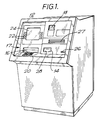
- a depository 10 is incorporated in an ATM 12 adapted to accept deposit items, represented by envelopes containing money (currency notes and/or cheques) or single sheet financial documents such as cheques or payment slips, through an entry slot 14, and to dispense currency notes through a slot 16, the slots 14 and 16 being included in a user interface 17 of the ATM 12.
- deposit item will be used to mean a deposited envelope or single sheet financial document.
- the user interface 17 also includes a card entry slot 18 through which a user of the machine inserts a customer identification card, a keyboard 20 and control keys 22 on which the user enters data such as a personal identification number (PIN) and the required transaction details, a lead-through display screen 24 on which user instructions and other information are displayed, a receipt slot 26 through which receipts are issued to a user, and a slot 27 through which envelopes are dispensed on request to a user.
- PIN personal identification number
- the entry slot 14 for deposit items is normally closed by a shutter 28 (not shown in Fig. 2A) connected to an actuating mechanism 30 (Fig. 6). Operation of the actuating mechanism 30 serves to retract the shutter 28 from its closed position so as to permit deposit items to be inserted in the depository 10 through the slot 14. Operation of the actuating mechanism 30 along with operation of other elements of the ATM 12 is controlled by electronic control means 32 as indicated in Fig. 6.
- the depository 10 has a transport mechanism which includes a common transport section 34 for transporting deposit items from the entry slot 14 along a common feed path defined by upper and lower guide means 36 and 38.
- the common transport section 34 includes a plurality of cooperating pairs of drive rolls 40, and further drive rolls 42 which cooperate with idler rolls 44, the rolls 40, 42 and 44 all being of compressible rubber.
- the rolls 42 and 44 are included in an alignment mechanism 46 in accordance with the present invention and, as will be described in more detail later, each of the rolls 42 includes a flat peripheral portion 48.
- Envelope and document feed paths branch off from the common feed path, the envelope feed path leading to an envelope processing module 50 as indicated by arrow 52, and the document feed path leading to a document processing module 54 as indicated by arrow 56.
- the drive rolls 40 and 42 are driven by a main reversible transport motor 58 (Fig. 6).
- a pivotably mounted divert gate 60 is positioned at the junction between the common feed path and envelope feed path, and a further pivotably mounted divert gate 62 is positioned at the junction between the common feed path and the document feed path.
- the divert gates 60 and 62 are normally in the home positions shown in solid outline in Figs. 2A and 2B, but are each selectively movable to an actuated position shown in chain outline under the control of a respective associated actuator 64 or 66 (Fig. 6).
- a thickness sensor 68 is positioned adjacent to the entry slot 14 of the depository 10, the sensor 68 being arranged to detect whether a deposit item has a thickness of at least one millimetre, which in the present embodiment is taken as being indicative that the deposit item is an envelope. If the thickness sensor 68 senses that a deposited item has a thickness of at least one millimetre, then it sends an appropriate output signal to the electronic control means 32.
- the thickness sensor 68 may be of known construction and operation.
- the thickness sensor 68 may include two cooperating rolls (not shown) which are moved apart as a deposit item passes between them, the above-mentioned output signal being generated if the rolls are moved apart by at least one millimetre.
- the alignment mechanism 46 is positioned adjacent to the end of the common feed path remote from the entry slot 14. As will be explained in more detail later, the alignment mechanism 46 serves to align a deposit item which is a single sheet financial document by moving the document transversely relative to the common feed path so as to bring a long edge of the document into parallel abutting contact with a reference surface 72 (Figs. 4 and 5) which is accurately parallel to the document feed path, the reference surface 72 forming part of the inner surface of a side frame of the depository 10.
- a document has been correctly aligned in this manner it has the correct orientation relative to the document feed path so that it is processed correctly as it is fed through the document processing module 54.
- the divert gate 62 remains in its home position but the divert gate 60 is moved to its actuated position as shown in chain outline in Fig. 2A.
- the operation of the motor 58 is then reversed so as to cause the common transport section 34 to move the envelope back along the common feed path towards the entry slot 14.
- the envelope is diverted by the diverter gate 60 into the envelope processing module 50.
- the envelope processing module 50 there is printed on the envelope appropriate information such as a serial number identifying the envelope, time and date. After passing through the module 50, the envelope is deposited in an envelope bin 74.
- the divert gate 62 is moved to its actuated position as shown in dotted outline. After having been aligned, the deposit item is moved by the common transport section 34 back along the common feed path towards the entry slot 14. Shortly after this reverse movement commences, the deposit item is diverted by the divert gate 62 into the document processing module 54. Included in the document processing module 54 are sensor means (not shown) for sensing whether the deposit item is correctly aligned. If the deposit item is not correctly aligned, the operation of a document transport motor 76 (Fig.
- the module 54 is reversed so as to feed the item back to the alignment mechanism 46 where the alignment operation is repeated.
- the procedure of aligning a deposit item and checking its alignment is repeated if necessary up to three times. If after three repeated alignment procedures the deposit item is still not correctly aligned, it is either fed back by the common transport section 34 along the common feed path to the entry slot 14 for collection by the user, or the item is diverted by the divert gate 60 into the envelope processing module 50 for feeding to the envelope bin 74 from where it can be collected for manual processing.
- the item is scanned automatically in known manner in order to determine whether it fulfils the criteria of being a financial document of predetermined type, of being correctly orientated and of being fully completed. If the deposit item does not fulfil these criteria, then the document transport motor 76 is reversed so as to return the item to the common transport path, after which the item is fed back to the entry slot 14 or fed to the envelope bin 74, as in the case of a misaligned item. If the deposit item does fulfil the above-mentioned criteria, then information carried by the item is processed in known manner by the module 54, and appropriate information (e.g. serial number identifying the document, date, time and ATM location) is printed on the document. Finally, the document is fed to a document bin module 78 where the document is stacked in orderly manner in an appropriate pocket of the bin module 78.
- appropriate information e.g. serial number identifying the document, date, time and ATM location
- the drive rolls 42 and the cooperating idler rolls 44 are included in the alignment mechanism 46.
- the drive rolls 42 and the idler rolls 44 are arranged in three sets of three rolls.
- the drive rolls 42 of each set are secured on a respective drive shaft 82 which extends transversely to the common feed path above a plate member 84 forming part of the upper guide means 36, and the idler rolls 44 of each set are rotatably mounted on a respective shaft 86 which extends transversely to the common feed path below a table 88 forming part of the lower guide means 38.
- a respective drive shaft 82 which extends transversely to the common feed path above a plate member 84 forming part of the upper guide means 36
- the idler rolls 44 of each set are rotatably mounted on a respective shaft 86 which extends transversely to the common feed path below a table 88 forming part of the lower guide means 38.
- the axes of the drive shafts 82 lie in the same horizontal plane and are spaced apart along the common feed path, and the axes of the shafts 86 also lie in a common horizontal plane and are respectively disposed immediately below the axes of the shafts 82.
- the drive shafts 82 are driven in unison by the main transport motor 58, and the drive rolls 42 are mounted on the shafts 82 such that all the flat peripheral portions 48 have the same orientation. As the drive rolls 42 rotate they respectively extend through slots 90 formed in the plate member 84. Similarly, the idler rolls 44 are respectively partially disposed in slots 92 formed in the table 88, with the uppermost parts of the peripheries of the rolls 44 being level with the upper surface of the table 88.
- one of the drive shafts 82 carries a flag formed by an extension (not shown) arranged to be sensed by sensor means (not shown) which applies signals to the electronic control means 32.
- alignment rolls 100 Disposed beneath the table 88 and extending in a horizontal direction parallel to the common feed path is a further drive shaft 94 which is driven by a reversible motor 96 via transmission means 98.
- Three transverse drive rolls 100 hereinafter referred to as alignment rolls 100, are secured on, and spaced apart along, the shaft 94. As shown in Figs. 2B and 3, one of the alignment rolls 100 is located between the intermediate idler roll 44 and that idler roll 44 nearest the entry slot 14, while the other two alignment rolls 100 are disposed between the intermediate idler roll 44 and that idler roll 44 furthest from the entry slot 14.
- Each of the alignment rolls 100 has a flat peripheral portion 102.
- the alignment rolls 100 are mounted on the shaft 94 so that at any instant all the flat peripheral portions 102 of the rolls 100 lie in the same plane. As the rolls 100 rotate, the arcuate portions of the peripheries thereof are respectively partially accommodated in three slots 104 formed in the table 88, with the uppermost parts of these arcuate portions extending slightly above (by 0.5 millimetre) the upper surface of the table 88. When rotation of the rolls 100 is stopped, the flat peripheral portions 102 are uppermost and disposed just below the lower surface of the table 88. In order to ensure that the rolls 100 are stopped with the flat peripheral portions 102 uppermost, the shaft 94 carries a flag represented by an extension 106 arranged to be sensed by sensor means (not shown) which applies signals to the electronic control means 32.
- each of the alignment rolls 100 comprises an inner member 108 of hard plastic material around which is formed a sleeve 110 of compressible rubber.
- Each roll 100 is cooperatively associated with a respective spring biased ball 112 of hard plastic material which is seated in an annular holding portion 114 of the table 88, the annular portion 114 forming the lower end of a cylindrical housing 116 for the ball 112.
- each ball 112 is urged by a respective compression spring 118 into engagement with the respective holding portion 114, with the lowermost portion of the ball 112 being level with the upper surface of the table 88 and opposite the respective roll 100 as shown in Fig. 4.
- Each compression spring 118 extends vertically inside the respective housing 116 between a closed upper end 120 of the housing 116 and a plastic member 122 which engages with the respective ball 112. It should be understood that each ball 112 is held in the respective housing 116 between the plastic member 122 and the annular portion 114 so as to be rotatable relative to the plate member 84.
- the motor 96 brings about rotation of the alignment rolls 100 in the course of an alignment operation, the rolls 100 being rotated first through one revolution in an anticlockwise direction (with reference to Figs. 4 and 5) and then through two revolutions in a clockwise direction.
- the arcuate peripheral portions thereof come into cooperative relationship with the balls 112 so as to grip the deposit item 124 between these arcuate portions and the balls 112 with the balls 112 being moved slightly upwardly against the action of the springs 118, as shown in Fig. 5.
- the deposit item 124 is first moved transversely to the common feed path away from the reference surface 72 and into contact with a side surface 126 opposite the reference surface 72, and is then moved transversely to the common feed path towards the reference surface 72 so as to bring a long edge of the deposit item 124 into parallel abutting contact with the reference surface 72, the balls 112 rotating in their respective housings 116 during movement of the deposit item 124.
- the reason for moving the deposit item 124 first away from the reference surface 72 during an alignment operation is to assist in de-skewing the deposit item 124 if it has been inserted in the entry slot 14 with a badly skewed orientation, and to remove any curl in the long edge of the deposit item 124 nearer the reference surface 72.
- the distance between the side surfaces 72 and 126 is 115 millimetres which is greater than the maximum width of a deposit item acceptable by the depository 10 and which is less than twice the minimum width of an acceptable deposit item.
- the distance between the upper surface of the table 88 and the lower surface of the plate member 84 is 7 millimetres which is slightly greater than the maximum thickness (6 millimetres) of a deposit item which can be inserted through the entry slot 14.
- optical sensor means 128 are located at the entry to the alignment mechanism 46, and optical sensor means 130 are located at the opposite end of the alignment mechanism 46, adjacent to the end of the common feed path remote from the entry slot 14.
- a user inserts his identification card into the card entry slot 18 and enters his PIN on the keyboard 20.
- a deposit transaction is then requested by the user using the control keys 22 and, if desired, he can request the ATM 12 to dispense an envelope, again by using the control keys 22.
- the shutter 28 is retracted by the actuating mechanism 30 and the user can then insert a deposit item into the entry slot 14.
- the deposit item is fed by the common transport section 34 through the thickness sensor 68 to the alignment mechanism 46.
- the common transport section 34 is stopped with the deposit item positioned approximately centrally with respect to the alignment mechanism 46 and with the flat peripheral portions 48 of the drive rolls 42 lowermost and out of contact with the deposit item.
- the thickness sensor 68 has sent an output signal to the electronic control means 32 indicating that the deposit item is an envelope, then, as previously described, the operation of the main transport motor 58 is reversed so as to cause the envelope to be fed by the transport section 34 into the envelope processing module 50. If the thickness sensor 68 has not sent an output signal to the electronic control means 32, thereby indicating that the deposit item is considered to be a single sheet document, then the common transport section 34 remains inoperative, and the alignment rolls 100 are rotated by the motor 96 under the control of the electronic control means 32.
- the deposit item is first moved laterally by the rolls 100 towards the side face 126 and is then moved laterally towards the reference surface 72 so as to bring a long edge of the deposit item into parallel abutting contact with the surface 72.
- the rolls 100 are then stopped in their home position with the flat peripheral surfaces 102 uppermost and with the deposit item being held between the balls 112 and the table 88.
- operation of the common transport section 34 is recommenced in a reverse sense to as to drive the deposit item back partly along the common feed path and into the document processing module 54, the divert gate 62 having previously been set to its actuated position as shown in dotted outline in Fig. 2B.
- the alignment mechanism 46 moved the deposit item laterally so as to bring a long edge of the deposit item into parallel abutting contact with the reference surface 72 will normally ensure that when the deposit item enters the document processing module 54 it is correctly aligned for proper processing by the module 54. It should be understood that one or more of the spring biased balls 112 remain in contact with the deposit item while it is being fed through the alignment mechanism 46 and until it leaves the mechanism 46, and this fact helps to ensure that the deposit item remains in contact with the reference surface 72 while being fed into the document processing module 54.
- the alignment mechanism 46 could include only two alignment rolls 100 and cooperating spring biased balls 112, or could incorporate four or more alignment rolls 100 and cooperating balls 112. What is important is that the alignment mechanism 46 should include at least two alignment rolls 100 spaced apart in a direction parallel to the common feed path and mounted with their axes non-perpendicular to (preferably substantially parallel to) this feed path.
- the alignment mechanism 46 described above has the advantages that it is of simple construction and is able to bring a deposit item into parallel abutting relationship with the reference surface 72 by means of a single lateral movement of the deposit item towards the reference surface 72. Also, the spring biased balls 112 used for aligning documents do not impede the passage through the alignment mechanism 46 of envelopes (up to 6 millimetres thick) which do not require to be aligned. Moreover, the balls 112 help to retain an aligned document in contact with the reference surface 72.
Landscapes
- Engineering & Computer Science (AREA)
- Mechanical Engineering (AREA)
- Registering Or Overturning Sheets (AREA)
Applications Claiming Priority (2)
| Application Number | Priority Date | Filing Date | Title |
|---|---|---|---|
| GB9323710 | 1993-11-15 | ||
| GB939323710A GB9323710D0 (en) | 1993-11-15 | 1993-11-15 | Document alignment system |
Publications (2)
| Publication Number | Publication Date |
|---|---|
| EP0653367A1 true EP0653367A1 (fr) | 1995-05-17 |
| EP0653367B1 EP0653367B1 (fr) | 1999-06-09 |
Family
ID=10745329
Family Applications (1)
| Application Number | Title | Priority Date | Filing Date |
|---|---|---|---|
| EP94308336A Expired - Lifetime EP0653367B1 (fr) | 1993-11-15 | 1994-11-11 | Système d'alignement de documents |
Country Status (6)
| Country | Link |
|---|---|
| US (1) | US5577719A (fr) |
| EP (1) | EP0653367B1 (fr) |
| JP (1) | JPH07187454A (fr) |
| DE (1) | DE69418972T2 (fr) |
| ES (1) | ES2133498T3 (fr) |
| GB (1) | GB9323710D0 (fr) |
Cited By (9)
| Publication number | Priority date | Publication date | Assignee | Title |
|---|---|---|---|---|
| GB2303845A (en) * | 1995-08-02 | 1997-03-05 | Pitney Bowes Inc | Envelope side registration apparatus combined with a stacker |
| EP1004440A3 (fr) * | 1998-11-24 | 2000-08-16 | Hewlett-Packard Company | Imprimante à jet d'encre à zones multiples |
| WO2002077933A1 (fr) * | 2001-03-28 | 2002-10-03 | Alberto Conti | Procede et machine pour compter et verifier du papier-monnaie et des cheques, apte a permettre des depots automatiques |
| ES2292281A1 (es) * | 2004-02-20 | 2008-03-01 | Fujitsu Frontech Limited | Mecanismo de transporte de medio, aparato de transporte de medio y metodo de transporte de medio. |
| EP1866881A4 (fr) * | 2005-03-09 | 2009-12-30 | Diebold Inc | Systeme et procede de guichet automatique d'acceptation de cheques et de distribution d'especes |
| WO2014086919A1 (fr) | 2012-12-07 | 2014-06-12 | Wobben Properties Gmbh | Bord de fuite de pale de rotor |
| DE102013202881A1 (de) | 2013-02-21 | 2014-08-21 | Wobben Properties Gmbh | Rotorblatthinterkante |
| DE102013204637A1 (de) | 2013-03-15 | 2014-09-18 | Wobben Properties Gmbh | Windenergieanlage |
| US10082129B2 (en) | 2012-12-07 | 2018-09-25 | Wobben Properties Gmbh | Wind turbine |
Families Citing this family (27)
| Publication number | Priority date | Publication date | Assignee | Title |
|---|---|---|---|---|
| US5927469A (en) * | 1996-06-17 | 1999-07-27 | Dunifon; Thomas A. | Method and apparatus for aligning sheets of material moving along a path of travel |
| US5697608A (en) * | 1996-06-26 | 1997-12-16 | Xerox Corporation | Agile lateral and shew sheet registration apparatus and method |
| NL1003631C2 (nl) * | 1996-07-18 | 1998-01-21 | Oce Tech Bv | Afdrukinrichting met rechtlegstation voor het aan weerszijden bedrukken van rechtgelegde ontvangstvellen. |
| US5913796A (en) * | 1996-09-04 | 1999-06-22 | International Billing Services, Inc. | Sheet packet hold-down apparatus |
| GB9717938D0 (en) | 1997-08-22 | 1997-10-29 | De La Rue Thomas & Co Ltd | Document alignment system |
| US6682068B1 (en) * | 1997-11-28 | 2004-01-27 | Diebold, Incorporated | Document alignment mechanism for currency recycling automated banking machine |
| WO1999061357A1 (fr) * | 1998-05-28 | 1999-12-02 | Citizen Watch Co., Ltd. | Appareil d'alimentation de materiau brut comportant une fonction de correction de direction |
| ATE327201T1 (de) * | 2001-07-30 | 2006-06-15 | Heidelberger Druckmasch Ag | Vorrichtung zum transport von blattförmigen bedruckstoffen |
| US7182010B2 (en) | 2001-07-30 | 2007-02-27 | Heidelberger Druckmaschinen Ag | Apparatus and process for producing different hole patterns in sheet-shaped print materials |
| US20030036468A1 (en) * | 2001-07-30 | 2003-02-20 | Kurt Blank | Device and method for automatic processing of sheet-shaped print materials with interchangeable functions |
| US6729780B2 (en) * | 2001-09-05 | 2004-05-04 | Agfa-Gevaert | Color proofer with registering means |
| US6805508B2 (en) * | 2002-03-28 | 2004-10-19 | Hewlett-Packard Development Company, L.P. | Skew-correcting media delivery system and method |
| DE10236028A1 (de) * | 2002-08-06 | 2004-02-19 | Giesecke & Devrient Gmbh | Vorrichtung und Verfahren für das Ausrichten von Banknoten |
| KR20040031935A (ko) * | 2002-10-07 | 2004-04-14 | 엘지엔시스(주) | 지폐자동입출금기의 지폐두께감지장치 |
| US6817609B2 (en) * | 2002-10-08 | 2004-11-16 | Xerox Corporation | Printer sheet lateral registration system with automatic upstream nip disengagements for different sheet size |
| US7416095B2 (en) * | 2003-03-10 | 2008-08-26 | Diebold Self-Service Systems Division Of Diebold, Incorporated | Cash dispensing automated banking machine deposit accepting system and method |
| DE20319272U1 (de) * | 2003-12-12 | 2005-04-21 | Psi Printer Systems International Gmbh | Einrichtung für Drucker o.dgl. zum Ausrichten der Blätter vor dem Druck |
| US20060049257A1 (en) * | 2004-08-09 | 2006-03-09 | 4Access Communications | Self-aligning contacts for material transport |
| US9382087B2 (en) * | 2004-11-03 | 2016-07-05 | Goss International Americas, Inc. | Compressible nip rolls for multiribbon transport |
| US8052041B2 (en) * | 2006-11-10 | 2011-11-08 | Diebold Self-Service Systems Division Of Diebold, Incorporated | Method of operation of card activated automated banking machine |
| US7934642B2 (en) * | 2006-11-10 | 2011-05-03 | Diebold Self-Service Systems Division Of Diebold, Incorporated | Method of operating banking system responsive to data bearing records |
| JP5100509B2 (ja) * | 2008-05-28 | 2012-12-19 | キヤノン株式会社 | シート搬送装置、画像形成装置及び画像読取装置 |
| JP2011255976A (ja) * | 2010-06-04 | 2011-12-22 | Japan Cash Machine Co Ltd | 紙葉類搬送装置 |
| US20110298172A1 (en) * | 2010-06-07 | 2011-12-08 | Japan Cash Machine Co., Ltd. | Document conveyor |
| US9114942B1 (en) * | 2014-06-27 | 2015-08-25 | Digital Check Corporation | Automatic document alignment |
| DE102017105842B4 (de) * | 2017-03-17 | 2019-05-29 | Wincor Nixdorf International Gmbh | Vorrichtung zum Ausrichten von Wertscheinen |
| DE102017105845A1 (de) | 2017-03-17 | 2018-09-20 | Wincor Nixdorf International Gmbh | Vorrichtung zum Ausrichten von Wertscheinen |
Citations (4)
| Publication number | Priority date | Publication date | Assignee | Title |
|---|---|---|---|---|
| DE512886C (de) * | 1928-10-10 | 1930-11-20 | Camco Machinery Ltd | Schraegwalzenfoerdertisch |
| EP0473884A1 (fr) * | 1990-09-07 | 1992-03-11 | Hewlett-Packard Company | Système d'alignement des feuilles dans une imprimante |
| EP0496398A2 (fr) * | 1991-01-24 | 1992-07-29 | Canon Kabushiki Kaisha | Appareil d'alimentation en feuilles |
| DE9210105U1 (de) * | 1992-07-28 | 1992-10-22 | Mathias Bäuerle GmbH, 7742 St Georgen | Transportvorrichtung für Papierbogen o.dgl. |
Family Cites Families (7)
| Publication number | Priority date | Publication date | Assignee | Title |
|---|---|---|---|---|
| US4143755A (en) * | 1975-09-29 | 1979-03-13 | Pullman Incorporated | Roller conveyor with alignment device |
| WO1980002336A1 (fr) * | 1979-04-20 | 1980-10-30 | Canon Kk | Dispositif d'orientation d'un texte |
| JPS5762138A (en) * | 1980-10-01 | 1982-04-15 | Fuji Xerox Co Ltd | Paper latera shifting apparatus |
| JPS58183551A (ja) * | 1982-04-20 | 1983-10-26 | Canon Inc | シ−ト送り整合装置 |
| GB8927225D0 (en) * | 1989-12-01 | 1990-01-31 | Ncr Co | Depository apparatus for envelopes and single sheets |
| FR2685310B1 (fr) * | 1991-12-24 | 1994-01-28 | Cga Hbs | Mecanisme pour l'introduction d'un objet plat vers un dispositif de traitement dudit objet. |
| US5280901A (en) * | 1993-03-24 | 1994-01-25 | Xerox Corporation | Sheet variable corrugating and feeding nip |
-
1993
- 1993-11-15 GB GB939323710A patent/GB9323710D0/en active Pending
-
1994
- 1994-09-23 US US08/311,245 patent/US5577719A/en not_active Expired - Lifetime
- 1994-11-11 EP EP94308336A patent/EP0653367B1/fr not_active Expired - Lifetime
- 1994-11-11 ES ES94308336T patent/ES2133498T3/es not_active Expired - Lifetime
- 1994-11-11 DE DE69418972T patent/DE69418972T2/de not_active Expired - Lifetime
- 1994-11-14 JP JP6279371A patent/JPH07187454A/ja active Pending
Patent Citations (4)
| Publication number | Priority date | Publication date | Assignee | Title |
|---|---|---|---|---|
| DE512886C (de) * | 1928-10-10 | 1930-11-20 | Camco Machinery Ltd | Schraegwalzenfoerdertisch |
| EP0473884A1 (fr) * | 1990-09-07 | 1992-03-11 | Hewlett-Packard Company | Système d'alignement des feuilles dans une imprimante |
| EP0496398A2 (fr) * | 1991-01-24 | 1992-07-29 | Canon Kabushiki Kaisha | Appareil d'alimentation en feuilles |
| DE9210105U1 (de) * | 1992-07-28 | 1992-10-22 | Mathias Bäuerle GmbH, 7742 St Georgen | Transportvorrichtung für Papierbogen o.dgl. |
Cited By (13)
| Publication number | Priority date | Publication date | Assignee | Title |
|---|---|---|---|---|
| GB2303845A (en) * | 1995-08-02 | 1997-03-05 | Pitney Bowes Inc | Envelope side registration apparatus combined with a stacker |
| US5651543A (en) * | 1995-08-02 | 1997-07-29 | Pitney Bowes Inc. | Envelope offset apparatus |
| GB2303845B (en) * | 1995-08-02 | 1998-10-28 | Pitney Bowes Inc | Envelope offset apparatus |
| EP1004440A3 (fr) * | 1998-11-24 | 2000-08-16 | Hewlett-Packard Company | Imprimante à jet d'encre à zones multiples |
| WO2002077933A1 (fr) * | 2001-03-28 | 2002-10-03 | Alberto Conti | Procede et machine pour compter et verifier du papier-monnaie et des cheques, apte a permettre des depots automatiques |
| ES2292281B1 (es) * | 2004-02-20 | 2009-06-08 | Fujitsu Frontech Limited | Mecanismo de transporte de un documento a imprimir, aparato de transporte y metodo de transporte del mismo. |
| ES2292281A1 (es) * | 2004-02-20 | 2008-03-01 | Fujitsu Frontech Limited | Mecanismo de transporte de medio, aparato de transporte de medio y metodo de transporte de medio. |
| EP1866881A4 (fr) * | 2005-03-09 | 2009-12-30 | Diebold Inc | Systeme et procede de guichet automatique d'acceptation de cheques et de distribution d'especes |
| EP1953712A3 (fr) * | 2005-03-09 | 2011-05-11 | Diebold, Incorporated | Système et procédé de machine bancaire d'acception des chèques et de distribution automatique d'argent |
| WO2014086919A1 (fr) | 2012-12-07 | 2014-06-12 | Wobben Properties Gmbh | Bord de fuite de pale de rotor |
| US10082129B2 (en) | 2012-12-07 | 2018-09-25 | Wobben Properties Gmbh | Wind turbine |
| DE102013202881A1 (de) | 2013-02-21 | 2014-08-21 | Wobben Properties Gmbh | Rotorblatthinterkante |
| DE102013204637A1 (de) | 2013-03-15 | 2014-09-18 | Wobben Properties Gmbh | Windenergieanlage |
Also Published As
| Publication number | Publication date |
|---|---|
| DE69418972D1 (de) | 1999-07-15 |
| EP0653367B1 (fr) | 1999-06-09 |
| ES2133498T3 (es) | 1999-09-16 |
| US5577719A (en) | 1996-11-26 |
| JPH07187454A (ja) | 1995-07-25 |
| GB9323710D0 (en) | 1994-01-05 |
| DE69418972T2 (de) | 1999-12-02 |
Similar Documents
| Publication | Publication Date | Title |
|---|---|---|
| EP0653367B1 (fr) | Système d'alignement de documents | |
| EP0653734B1 (fr) | Appareil de dépÔt pour enveloppes et feuilles séparées | |
| EP1357069B1 (fr) | Guichet automatique bancaire | |
| EP0606959B1 (fr) | Appareil pour le dépÔt d'articles | |
| US5136144A (en) | Depository apparatus for envelopes and single sheets | |
| US5683079A (en) | Document processing apparatus | |
| EP1049642B1 (fr) | Systeme de desempilage de documents pour guichet automatique bancaire a recirculation de billets de banque usages | |
| US6331000B1 (en) | Currency recycling system and method for automated banking machine | |
| EP1034125B1 (fr) | Mecanisme d'alignement de documents destine a un guichet automatique bancaire recyclant la monnaie | |
| EP1032477A4 (fr) | Guichet automatique bancaire a recyclage des billets usages | |
| JPH034957B2 (fr) | ||
| EP0965955B1 (fr) | Dispositif pour délivrer des feuilles dans une machine bancaire | |
| KR100526581B1 (ko) | 지폐류입출금기의 출금장치 | |
| JP2914463B2 (ja) | 紙幣入出金装置 | |
| JP2753050B2 (ja) | 冊子類の改頁装置 | |
| JPS5839393A (ja) | 紙葉類受入装置 | |
| EP1752404B1 (fr) | Système de stockage et de recyclage de supports pour guichet automatique bancaire | |
| JPH03296891A (ja) | 紙幣入出金装置 | |
| JPS6037092A (ja) | 伝票印字方式 |
Legal Events
| Date | Code | Title | Description |
|---|---|---|---|
| PUAI | Public reference made under article 153(3) epc to a published international application that has entered the european phase |
Free format text: ORIGINAL CODE: 0009012 |
|
| AK | Designated contracting states |
Kind code of ref document: A1 Designated state(s): DE ES FR GB IT |
|
| 17P | Request for examination filed |
Effective date: 19951117 |
|
| RAP1 | Party data changed (applicant data changed or rights of an application transferred) |
Owner name: NCR INTERNATIONAL, INC. |
|
| GRAG | Despatch of communication of intention to grant |
Free format text: ORIGINAL CODE: EPIDOS AGRA |
|
| GRAG | Despatch of communication of intention to grant |
Free format text: ORIGINAL CODE: EPIDOS AGRA |
|
| GRAH | Despatch of communication of intention to grant a patent |
Free format text: ORIGINAL CODE: EPIDOS IGRA |
|
| 17Q | First examination report despatched |
Effective date: 19980903 |
|
| GRAH | Despatch of communication of intention to grant a patent |
Free format text: ORIGINAL CODE: EPIDOS IGRA |
|
| GRAA | (expected) grant |
Free format text: ORIGINAL CODE: 0009210 |
|
| AK | Designated contracting states |
Kind code of ref document: B1 Designated state(s): DE ES FR GB IT |
|
| REF | Corresponds to: |
Ref document number: 69418972 Country of ref document: DE Date of ref document: 19990715 |
|
| REG | Reference to a national code |
Ref country code: ES Ref legal event code: FG2A Ref document number: 2133498 Country of ref document: ES Kind code of ref document: T3 |
|
| ET | Fr: translation filed | ||
| PLBE | No opposition filed within time limit |
Free format text: ORIGINAL CODE: 0009261 |
|
| STAA | Information on the status of an ep patent application or granted ep patent |
Free format text: STATUS: NO OPPOSITION FILED WITHIN TIME LIMIT |
|
| 26N | No opposition filed | ||
| REG | Reference to a national code |
Ref country code: GB Ref legal event code: IF02 |
|
| REG | Reference to a national code |
Ref country code: GB Ref legal event code: 746 Effective date: 20091111 |
|
| PG25 | Lapsed in a contracting state [announced via postgrant information from national office to epo] |
Ref country code: IT Free format text: LAPSE BECAUSE OF NON-PAYMENT OF DUE FEES Effective date: 20091111 |
|
| PGRI | Patent reinstated in contracting state [announced from national office to epo] |
Ref country code: IT Effective date: 20110616 |
|
| PGFP | Annual fee paid to national office [announced via postgrant information from national office to epo] |
Ref country code: GB Payment date: 20131127 Year of fee payment: 20 Ref country code: DE Payment date: 20131127 Year of fee payment: 20 Ref country code: FR Payment date: 20131118 Year of fee payment: 20 |
|
| PGFP | Annual fee paid to national office [announced via postgrant information from national office to epo] |
Ref country code: ES Payment date: 20131126 Year of fee payment: 20 Ref country code: IT Payment date: 20131125 Year of fee payment: 20 |
|
| REG | Reference to a national code |
Ref country code: DE Ref legal event code: R071 Ref document number: 69418972 Country of ref document: DE |
|
| REG | Reference to a national code |
Ref country code: GB Ref legal event code: PE20 Expiry date: 20141110 |
|
| REG | Reference to a national code |
Ref country code: ES Ref legal event code: FD2A Effective date: 20150126 |
|
| PG25 | Lapsed in a contracting state [announced via postgrant information from national office to epo] |
Ref country code: GB Free format text: LAPSE BECAUSE OF EXPIRATION OF PROTECTION Effective date: 20141110 |
|
| PG25 | Lapsed in a contracting state [announced via postgrant information from national office to epo] |
Ref country code: ES Free format text: LAPSE BECAUSE OF EXPIRATION OF PROTECTION Effective date: 20141112 |