EP0654438B1 - Vorrichtung zum automatischen Umschalten von Rohrleitungen - Google Patents
Vorrichtung zum automatischen Umschalten von Rohrleitungen Download PDFInfo
- Publication number
- EP0654438B1 EP0654438B1 EP94117117A EP94117117A EP0654438B1 EP 0654438 B1 EP0654438 B1 EP 0654438B1 EP 94117117 A EP94117117 A EP 94117117A EP 94117117 A EP94117117 A EP 94117117A EP 0654438 B1 EP0654438 B1 EP 0654438B1
- Authority
- EP
- European Patent Office
- Prior art keywords
- pipes
- axis
- material feeding
- parallel
- switching device
- Prior art date
- Legal status (The legal status is an assumption and is not a legal conclusion. Google has not performed a legal analysis and makes no representation as to the accuracy of the status listed.)
- Expired - Lifetime
Links
- 239000000463 material Substances 0.000 claims description 112
- 230000008878 coupling Effects 0.000 claims description 6
- 238000010168 coupling process Methods 0.000 claims description 6
- 238000005859 coupling reaction Methods 0.000 claims description 6
- 241001137251 Corvidae Species 0.000 claims description 2
- 235000015108 pies Nutrition 0.000 claims description 2
- 238000000034 method Methods 0.000 description 7
- 238000004140 cleaning Methods 0.000 description 4
- 238000010586 diagram Methods 0.000 description 3
- 239000000839 emulsion Substances 0.000 description 3
- 238000012423 maintenance Methods 0.000 description 3
- 239000000126 substance Substances 0.000 description 3
- 238000007796 conventional method Methods 0.000 description 2
- 238000011109 contamination Methods 0.000 description 1
- 238000010924 continuous production Methods 0.000 description 1
- 239000012153 distilled water Substances 0.000 description 1
- 230000000694 effects Effects 0.000 description 1
- 238000004519 manufacturing process Methods 0.000 description 1
- 239000004810 polytetrafluoroethylene Substances 0.000 description 1
- 229920001343 polytetrafluoroethylene Polymers 0.000 description 1
- 239000007787 solid Substances 0.000 description 1
- XLYOFNOQVPJJNP-UHFFFAOYSA-N water Chemical compound O XLYOFNOQVPJJNP-UHFFFAOYSA-N 0.000 description 1
Images

Classifications
-
- B—PERFORMING OPERATIONS; TRANSPORTING
- B67—OPENING, CLOSING OR CLEANING BOTTLES, JARS OR SIMILAR CONTAINERS; LIQUID HANDLING
- B67D—DISPENSING, DELIVERING OR TRANSFERRING LIQUIDS, NOT OTHERWISE PROVIDED FOR
- B67D7/00—Apparatus or devices for transferring liquids from bulk storage containers or reservoirs into vehicles or into portable containers, e.g. for retail sale purposes
- B67D7/06—Details or accessories
- B67D7/78—Arrangements of storage tanks, reservoirs or pipe-lines
-
- B—PERFORMING OPERATIONS; TRANSPORTING
- B65—CONVEYING; PACKING; STORING; HANDLING THIN OR FILAMENTARY MATERIAL
- B65G—TRANSPORT OR STORAGE DEVICES, e.g. CONVEYORS FOR LOADING OR TIPPING, SHOP CONVEYOR SYSTEMS OR PNEUMATIC TUBE CONVEYORS
- B65G53/00—Conveying materials in bulk through troughs, pipes or tubes by floating the materials or by flow of gas, liquid or foam
- B65G53/34—Details
- B65G53/52—Adaptations of pipes or tubes
- B65G53/56—Switches
Definitions
- This invention relates to a system which continuously supplies a number of kinds of solution materials from material storing tanks to a preparing/mixing device, and more particularly to a device for automatically switching a destination to which the solution materials are to be supplied.
- one of the connecting joints of two hoses to be connected to each other is moved vertically, while the other is moved horizontally, until they are connected to each other.
- an object of the invention is to provide an automatic pipeline switching device which is free from the problem that, in changing the destination to which a number of kinds of solution materials are to be supplied during continuous production, changing the material supply pipeline takes a lot of time and labor, and which is able to handle a number of pipelines effectively, and is compact in arrangement and simple in maintenance.
- an automatic pipeline switching device which, according to the invention, comprises:
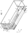
- FIG. 1 is a perspective view showing the arrangement of an automatic pipeline switching device according to the invention.
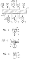
- FIG. 2 is an explanatory diagram for a description of processes performed by the device of the invention.
- FIGS. 3 and 4 are a front view and a side view, respectively, showing of a pipe connecting/disconnecting unit which disengages connecting joints from each other.
- FIG. 5 is a front view showing the pipe engaging/disengaging unit which engages the connecting joints with each other.
- FIG. 6 is an explanatory diagram for a description of a conventional method of using valves to change the connections of material supply pipelines.
- FIG. 2 is a diagram for a description of processes performed by an automatic pipeline switching device according to the invention.
- reference numeral 9 designates the automatic pipeline switching device according to the invention.
- Solution materials stored in a plurality of material storing tanks 7 are supplied through the automatic pipeline switching device 9 to a selected one of the preparing/mixing devices 8.
- the device 9 of the invention automatically changes the connection of the material supply pipeline according to an instruction from a control unit.
- FIG. 1 is a perspective view of the automatic pipeline switching device 9 of the invention.
- the automatic pipeline switching device 9 comprises: material receiving pipes 1 for receiving the solution materials from the material storing tanks 7; material feeding pipes 2 for delivering the solution materials to the preparing/mixing devices; a holder 3 for holding the connecting joint 2a of a selected one of the material feeding pipes (hereinafter referred to as "a material-feeding-pipe's connecting joint 2a", when applicable); a Z-direction moving unit 4 for moving the holder 3 in the direction of Z-axis; an X-direction moving unit 5 for moving the holder 3 in the direction of X-axis; and pipe connecting/disconnecting units 6 each of which is operated to connect the connecting joint 1a of a selected one of the material receiving pipes (hereinafter referred to as "a material-receiving-pipe's connecting joint 1a", when applicable) to a selected material-feeding-pipe's connecting joint 2a to form a material flow path.
- the number of material receiving pipes 1 is equal to that of the material storing tanks.
- Each of the material receiving pipes 1 has the material-feeding-pipe's connecting joint 2 and the pipe connecting/disconnecting unit 6 at one end, and the other end is connected to the respective material storing tank.
- FIGS. 3 through 5 shows the connecting position A of one of the material receiving pipes 1, where the material-receiving-pipe's connecting joint 1a is connected to or disconnected from the material-feeding-pipe's connecting joint 2a.
- FIGS. 3 and 4 show the disengagement of the connecting joints 1a and 2a
- FIG. 5 shows the engagement of them.
- reference character 6a designates a driving section in each of the pipe connecting/disconnecting units 6.
- the drive section 6a may be provided according to a conventional method using pneumatic energy or electrical energy.
- the pipe connecting/disconnecting unit 6 being driven by the driving section 6a, holds the material-feeding-pipe's connecting joint 2a and pushes the back of the material-receiving-pipe's connecting joint 1a until the seal surfaces of those connecting joints 1a and 2a are in close contact with each other, thus forming a material flow path.
- the number of the material feeding pipes 2 is equal to that of the material feeding pipes of the material preparing/mixing devices through which the materials are delivered out.
- Each of the material feeding pipes 2 is made up of the connecting joint 2a which is to be connected to the material receiving pipe, a solid pipe 2b in parallel with Y-axis, a flexible hose 2c in parallel with Z-axis, and a flexible hose 2d in parallel with X-axis, which are connected to one another in the stated order.
- the free end of the flexible hose 2d is connected to the respective material preparing/mixing device.
- the rigid pipe 2b in parallel with Y-axis is arranged in a Y-Z plane.
- the rigid pipes 2b thus arranged are larger in length upwardly, which prevents the interference of the flexible hoses in parallel with Z-axis and the flexible hoses in parallel with X-axis with each other.
- the flexible hoses 2c and 2d are supported with wiring cable bearers or the like, so that they may not come off the X-Z planes during the movement of the rigid pipes 2b.
- the holder 3 set on the X-direction moving unit 5 is moved by the Z-direction moving unit 4 and the X-direction moving unit 5 to a standby position where the selected joint 2a is located.
- the holder 3 picks up the connecting joint 2a, and moves it until it is confronted with the predetermined material receiving pipe 1.
- the pipe connecting/disconnecting unit 6 operates to connect the material-receiving-pipe's connecting joint to the material-feeding-pipe's connecting joint, to form the material flow path.
- the pipe connecting/disconnecting unit 6 When it is required to disconnect the material receiving pipe 1 from the material feeding pipe 2, the pipe connecting/disconnecting unit 6 operates to disconnect the connecting joint of the material receiving pipe 1 from the connecting joint of the material feeding pipe 2. Thereafter, the material feeding pipe 2 thus disconnected is returned to the original position with the aid of the holder 3, the Z-direction moving unit 4 and the X-direction moving unit 5.
- the operations of disengaging the connecting joints by the pipe connecting/disconnecting units, and the operation of moving the connecting joints by the holder 3, the Z-direction moving unit 4, and the X-direction moving unit 5 are repeatedly carried out while the rigid pipes of the material feeding pipes 2 are selected successively beginning with the longest one which is located uppermost in the direction of Z-axis.
- the pipes are cleaned with a cleaning solution supplied through cleaning-solution supplying pipes 10 which are connected to the material receiving pipes 1, respectively. As shown in FIG. 1, the cleaning-solution supplying pipes 10 are connected to a common cleaning solution header pipe 12. Valves 11 are operated with an optionally determined sequence, to clean each of the pipes.
- the apparatus of the present invention is used for producing sixty-eight (68) kinds of photographic emulsion, and it is provided at an intermediate position between forty (40) material tanks storing forty (40) kinds of chemicals for photographic emulsion, such as macromolecular solution dissolved in distilled water or organic solution, and twenty-two (22) material feeding pumps.
- the apparatus connects some necessary material storing tanks of the forty (40) material storing tanks and material feeding pumps are automatically by pipelines.
- the materials from the material storing tanks to the material feeding pumps are fed by gravitation feeding.
- the apparatus at most twelve (12) of the material storing tanks are connected with the material feeding pumps corresponding to one kind of material. There are sixty-eight (68) kinds of patterns of paths as the same number (68) kinds of materials, since a pattern of path from a material storing tank to a material feeding pump varies corresponding to one material. Forty (40) material-receiving pipe 1 connected with forty (40) material storing tanks and twenty-two (22) material-feeding pipe 2 connected with twenty-two (22) material feeding pumps for feeding materials are provided in the apparatus.
- the diameter of the pipeline is 3424 mm in width, 2322.5 mm in height, and 1702 mm in depth.
- the quality of material of the material-receiving pipe 1 is SUS 316, and the size of pipe is 1/2 inches.
- the material-feeding pipe 2 comprises a rigid pipe 2b which is 1/2 inches in size and is made of SUS 316, and a flexible pipe which is 1/2 inches in size and is made of PTFE. It took 1 minute at most to connect one 1 and one 2. Further, it took 9 minutes and 30 seconds to connect twelve (12) 1 and twelve (12) 2. Comparing with the conventional art by which it takes twenty-two (22) to do so, it was possible to shorten much time according to the present invention.
- the material appropriately used in the present invention is photographical emulsion.
- the number of material storing tanks is from twenty (20) to sixty (60)
- the number of material feeding pumps is from ten (10) to forty (40)
- the number of pattern of pipeline is from fifty (50) to a hundred (100).
- the diameter of the pipeline is usually from 1/8 to 1 inches.
Landscapes
- Engineering & Computer Science (AREA)
- Mechanical Engineering (AREA)
- Pipeline Systems (AREA)
Claims (5)
- Automatisches Rohrleitungs-Umschaltgerät, welches umfaßt:eine Vielzahl von Materialaufnahmerohren, die jeweils an einer Vielzahl von Material-Speichertanks angeschlossen sind;eine Vielzahl von Materialzuführrohren, die jeweils an einer Vielzahl von Lösungs-Herstell/Misch-Geräten angeschlossen sind;einen Halter zum Halten der Verbindungsteile der Materialzuführrohre; undMittel zum Bewegen des Halters in einer Z-Achsen-Richtung und in einer X-Achsen-Richtung,
in welchem Gerätdie Verbindungsteile der Materialaufnahmerohre in einer in der X-Achsen-Richtung verlaufenden Linie angeordnet sind,die Verbindungsteile der Materialzuführrohre in einem Bereitschaftsbereich in solcher Weise gehalten werden, daß die Verbindungsteile der Materialzuführrohre in einer in der Z-Achsen-Richtung verlaufenden Linie angeordnet sind,zur Y-Achse parallele starre Rohre, zur Z-Achse parallele flexible Schläuche und zur X-Achse parallele flexible Schläuche in dieser festgestellten Reihenfolge an den Verbindungsteilen der jeweiligen Materialzuführrohre angeschlossen werden, wobei die freien Enden der zur X-Achse parallelen flexiblen Schläuche an den Lösungs-Herstell/Misch-Geräten angeschlossen sind,die starren Rohre in dem Bereitschaftsbereich angeordnet sind und zu der Oberseite des Bereitschaftsbereiches hin mit jeweils größeren Längen versehen werden, um gegenseitige Störung der zu der Z-Achse parallelen flexiblen Schläuche mit den zu der X-Achse parallelen flexiblen Schläuchen zu verhindern,wobei das Bewegungsmittel arbeitet, den Halter zu dem Bereitschaftsbereich zu bewegen, wo der Halter die Verbindungskupplung eines ausgewählten der Materialzuführrohre hält, und dann den Halter zu der Verbindungskupplung eines ausgewählten der Materialaufnahmerohre zu bewegen, um diese Verbindungskupplungen miteinander zu verbinden. - Automatisches Rohrleitungs-Umschaltgerät nach Anspruch 1, bei dem die jeweiligen Rohrverbindungs/Löse-Vorgänge wiederholt ausgeführt werden, während die starren Rohre, welche die anzuschließenden Materialzuführrohre bilden, der Reihe nach angewählte werden, beginnend mit dem kürzesten, das zuunterst in Richtung der Z-Achse gelegen ist.
- Automatisches Rohrleitungs-Umschaltgerät nach Anspruch 1 oder 2, bei dem die Anzahl der Materialspeichertanks von 20 bis 60 beträgt.
- Automatisches Rohrleitungs-Umschaltgerät nach Anspruch 3, bei dem die Anzahl der Kombination von Rohren von 50 bis 100 beträgt.
- Automatisches Rohrleitungs-Umschaltgerät nach Anspruch 1, 2 oder 4, bei dem die Materialien Materialien für fotographische Produkte sind.
Applications Claiming Priority (2)
| Application Number | Priority Date | Filing Date | Title |
|---|---|---|---|
| JP29237093A JP3274260B2 (ja) | 1993-10-29 | 1993-10-29 | 溶液供給配管自動切替装置 |
| JP292370/93 | 1993-10-29 |
Publications (2)
| Publication Number | Publication Date |
|---|---|
| EP0654438A1 EP0654438A1 (de) | 1995-05-24 |
| EP0654438B1 true EP0654438B1 (de) | 1998-02-04 |
Family
ID=17780926
Family Applications (1)
| Application Number | Title | Priority Date | Filing Date |
|---|---|---|---|
| EP94117117A Expired - Lifetime EP0654438B1 (de) | 1993-10-29 | 1994-10-28 | Vorrichtung zum automatischen Umschalten von Rohrleitungen |
Country Status (4)
| Country | Link |
|---|---|
| US (1) | US5505496A (de) |
| EP (1) | EP0654438B1 (de) |
| JP (1) | JP3274260B2 (de) |
| DE (1) | DE69408408T2 (de) |
Families Citing this family (9)
| Publication number | Priority date | Publication date | Assignee | Title |
|---|---|---|---|---|
| AU7085696A (en) * | 1996-09-18 | 1998-04-14 | Giuseppe Guglielminetti | Apparatus for selectively supplying fluid products from a plurality of sources to a plurality of destinations |
| JP2000274598A (ja) * | 1999-03-26 | 2000-10-03 | Toyo Eng Corp | 改良された多目的生産装置およびそれを用いる多目的生産方法 |
| US6170515B1 (en) | 1999-06-24 | 2001-01-09 | Parmenlo, Llc | Piping manifold with quick connect couplers |
| US6319399B1 (en) | 1999-06-24 | 2001-11-20 | Dialysis Systems, Inc. | Isolation block |
| EP1161983A3 (de) * | 2000-06-07 | 2004-06-09 | Fuji Photo Film Co., Ltd. | Verfahren und System zur Optimierung eines diskontinuierlichen Verfahrens zur Herstellung von Lösungen |
| US10131506B2 (en) * | 2014-12-09 | 2018-11-20 | Maguire Products, Inc. | Selective matrix conveyance apparatus and methods for granular resin material |
| BE1025760B1 (nl) * | 2018-04-10 | 2019-07-03 | Constructie Lambrecht Nv | Inrichting voor geautomatiseerde logische koppelingen aan trailer compartimenten |
| CN108533963B (zh) * | 2018-05-18 | 2025-01-07 | 黎明职业大学 | 一种助剂自动计量输送系统及其使用方法 |
| CN117646873A (zh) * | 2023-08-18 | 2024-03-05 | 中化工储运有限公司 | 一种长输管道顺序输送混油切割装置及方法 |
Family Cites Families (11)
| Publication number | Priority date | Publication date | Assignee | Title |
|---|---|---|---|---|
| SU855325A1 (ru) * | 1978-12-21 | 1981-08-15 | Государственный научно-исследовательский институт теплоэнергетического приборостроения | Пневматический многоканальный разъем |
| EP0254764B1 (de) * | 1986-07-31 | 1990-07-25 | Dover Corporation | Vorrichtung zum wahlweisen Verbinden mindestens einer ersten stationären Leitung für Strömungsmittel mit einer Vielzahl von zweiten stationären Leitungen |
| US4790568A (en) * | 1986-07-31 | 1988-12-13 | Dover Corporation | Apparatus for selective combination of at least one first stationary pipeline for liquids with a plurality of second stationary pipelines |
| GB2208088B (en) * | 1987-04-21 | 1991-08-07 | Weldsil Engineering Company Li | Connection assembly of a gas cylinder filling arrangement |
| FR2659418B1 (fr) * | 1990-03-09 | 1992-07-10 | Fmc Europe | Installation de connexion selective temporaire a entrees et sorties de fluide multiples. |
| DE4014666C1 (de) * | 1990-05-08 | 1991-11-21 | Mercedes-Benz Aktiengesellschaft, 7000 Stuttgart, De | |
| JP2937454B2 (ja) * | 1990-10-19 | 1999-08-23 | 日東工器株式会社 | 複数の配管継手部材の同時接続装置 |
| FR2680559B1 (fr) * | 1991-08-21 | 1993-11-26 | Fmc Europe Sa | Installation de connexion selective temporaire a entrees et sorties multiples. |
| JP2591394B2 (ja) * | 1991-12-26 | 1997-03-19 | 日立プラント建設株式会社 | 配管の接続装置 |
| JPH0812000B2 (ja) * | 1992-02-06 | 1996-02-07 | 東洋エンジニアリング株式会社 | 可撓性配管自動接続装置およびその管理システム |
| JPH0656200A (ja) * | 1992-07-31 | 1994-03-01 | Tominaga Oil Pump Mfg Co Ltd | 給油装置の配管構造 |
-
1993
- 1993-10-29 JP JP29237093A patent/JP3274260B2/ja not_active Expired - Fee Related
-
1994
- 1994-10-24 US US08/327,697 patent/US5505496A/en not_active Expired - Lifetime
- 1994-10-28 EP EP94117117A patent/EP0654438B1/de not_active Expired - Lifetime
- 1994-10-28 DE DE69408408T patent/DE69408408T2/de not_active Expired - Fee Related
Also Published As
| Publication number | Publication date |
|---|---|
| JP3274260B2 (ja) | 2002-04-15 |
| DE69408408D1 (de) | 1998-03-12 |
| US5505496A (en) | 1996-04-09 |
| DE69408408T2 (de) | 1998-05-20 |
| JPH07127800A (ja) | 1995-05-16 |
| EP0654438A1 (de) | 1995-05-24 |
Similar Documents
| Publication | Publication Date | Title |
|---|---|---|
| US5505496A (en) | Automatic pipeline switching device | |
| EP0092534B2 (de) | Einrichtung zur auswechselbaren Befestigung von Werkzeugen an einem Industrieroboter | |
| EP1391680A1 (de) | Halbautomatischer Reiniger für Rohre | |
| US5803599A (en) | Apparatus and method for mixing chemicals to be used in chemical-mechanical polishing procedures | |
| WO2017064273A1 (en) | System for cleaning an object such as a heat exchanger | |
| WO2006013644A1 (ja) | 生産システム | |
| EP0771235B1 (de) | Vorrichtung und methode zur anwendung beim chemischen-mechanischen polieren | |
| CN111853546B (zh) | 化学品自动供给装置 | |
| US5215131A (en) | Automatic liquid delivery system | |
| US5160173A (en) | Selective pipe connection apparatus with multiple fluid inlets and outlets | |
| CN115742274A (zh) | 一种pvc管对接装置 | |
| JP3316620B2 (ja) | 自動管内面洗浄装置 | |
| JP3006457B2 (ja) | 複数配管の着脱式切替装置 | |
| JPH0812000B2 (ja) | 可撓性配管自動接続装置およびその管理システム | |
| JP3429916B2 (ja) | 配管自動接続切替え装置 | |
| CN210207905U (zh) | 一种吹气除尘辅助装置及具有其的avi检测设备 | |
| CN223137319U (zh) | 一种染料自动上料装置 | |
| JPH06159600A (ja) | 切替ステーション用自動配管接続装置 | |
| JPH09137899A (ja) | 配管自動接続切替え装置 | |
| JP3584083B2 (ja) | 配管自動接続切替え装置 | |
| JPH0680200A (ja) | ホースユニット移送接続と回分生産システム | |
| JPH0825600B2 (ja) | 切替えステーション配管自動接続装置およびその管理システム | |
| JP2003053288A (ja) | 細管保守点検装置 | |
| JPH01283496A (ja) | 自動管路接続装置 | |
| CN116140978A (zh) | 锁付装置及锁付设备 |
Legal Events
| Date | Code | Title | Description |
|---|---|---|---|
| PUAI | Public reference made under article 153(3) epc to a published international application that has entered the european phase |
Free format text: ORIGINAL CODE: 0009012 |
|
| AK | Designated contracting states |
Kind code of ref document: A1 Designated state(s): DE FR GB NL |
|
| 17P | Request for examination filed |
Effective date: 19951013 |
|
| GRAG | Despatch of communication of intention to grant |
Free format text: ORIGINAL CODE: EPIDOS AGRA |
|
| 17Q | First examination report despatched |
Effective date: 19970407 |
|
| GRAG | Despatch of communication of intention to grant |
Free format text: ORIGINAL CODE: EPIDOS AGRA |
|
| GRAH | Despatch of communication of intention to grant a patent |
Free format text: ORIGINAL CODE: EPIDOS IGRA |
|
| GRAH | Despatch of communication of intention to grant a patent |
Free format text: ORIGINAL CODE: EPIDOS IGRA |
|
| GRAA | (expected) grant |
Free format text: ORIGINAL CODE: 0009210 |
|
| AK | Designated contracting states |
Kind code of ref document: B1 Designated state(s): DE FR GB NL |
|
| PG25 | Lapsed in a contracting state [announced via postgrant information from national office to epo] |
Ref country code: NL Free format text: LAPSE BECAUSE OF FAILURE TO SUBMIT A TRANSLATION OF THE DESCRIPTION OR TO PAY THE FEE WITHIN THE PRESCRIBED TIME-LIMIT Effective date: 19980204 Ref country code: FR Free format text: LAPSE BECAUSE OF FAILURE TO SUBMIT A TRANSLATION OF THE DESCRIPTION OR TO PAY THE FEE WITHIN THE PRESCRIBED TIME-LIMIT Effective date: 19980204 |
|
| REF | Corresponds to: |
Ref document number: 69408408 Country of ref document: DE Date of ref document: 19980312 |
|
| NLV1 | Nl: lapsed or annulled due to failure to fulfill the requirements of art. 29p and 29m of the patents act | ||
| EN | Fr: translation not filed | ||
| PG25 | Lapsed in a contracting state [announced via postgrant information from national office to epo] |
Ref country code: GB Free format text: LAPSE BECAUSE OF NON-PAYMENT OF DUE FEES Effective date: 19981028 |
|
| PLBE | No opposition filed within time limit |
Free format text: ORIGINAL CODE: 0009261 |
|
| STAA | Information on the status of an ep patent application or granted ep patent |
Free format text: STATUS: NO OPPOSITION FILED WITHIN TIME LIMIT |
|
| 26N | No opposition filed | ||
| GBPC | Gb: european patent ceased through non-payment of renewal fee |
Effective date: 19981028 |
|
| PGFP | Annual fee paid to national office [announced via postgrant information from national office to epo] |
Ref country code: DE Payment date: 20071025 Year of fee payment: 14 |
|
| PG25 | Lapsed in a contracting state [announced via postgrant information from national office to epo] |
Ref country code: DE Free format text: LAPSE BECAUSE OF NON-PAYMENT OF DUE FEES Effective date: 20090501 |