EP0654571B1 - Procede d'assemblage de modules de zone d'une construction a structure en acier - Google Patents
Procede d'assemblage de modules de zone d'une construction a structure en acier Download PDFInfo
- Publication number
- EP0654571B1 EP0654571B1 EP94914616A EP94914616A EP0654571B1 EP 0654571 B1 EP0654571 B1 EP 0654571B1 EP 94914616 A EP94914616 A EP 94914616A EP 94914616 A EP94914616 A EP 94914616A EP 0654571 B1 EP0654571 B1 EP 0654571B1
- Authority
- EP
- European Patent Office
- Prior art keywords
- module
- gate
- assemblies
- truss
- modules
- Prior art date
- Legal status (The legal status is an assumption and is not a legal conclusion. Google has not performed a legal analysis and makes no representation as to the accuracy of the status listed.)
- Expired - Lifetime
Links
- 238000010276 construction Methods 0.000 title claims abstract description 71
- 229910000831 Steel Inorganic materials 0.000 title claims abstract description 49
- 239000010959 steel Substances 0.000 title claims abstract description 49
- 230000000712 assembly Effects 0.000 claims abstract description 73
- 238000000429 assembly Methods 0.000 claims abstract description 73
- 238000000034 method Methods 0.000 claims abstract description 30
- 230000003028 elevating effect Effects 0.000 claims description 14
- 238000009434 installation Methods 0.000 description 17
- 239000000463 material Substances 0.000 description 6
- QNRATNLHPGXHMA-XZHTYLCXSA-N (r)-(6-ethoxyquinolin-4-yl)-[(2s,4s,5r)-5-ethyl-1-azabicyclo[2.2.2]octan-2-yl]methanol;hydrochloride Chemical compound Cl.C([C@H]([C@H](C1)CC)C2)CN1[C@@H]2[C@H](O)C1=CC=NC2=CC=C(OCC)C=C21 QNRATNLHPGXHMA-XZHTYLCXSA-N 0.000 description 2
- 238000003780 insertion Methods 0.000 description 2
- 230000037431 insertion Effects 0.000 description 2
- 238000009628 steelmaking Methods 0.000 description 2
- 239000000126 substance Substances 0.000 description 2
- 238000007796 conventional method Methods 0.000 description 1
- 230000003247 decreasing effect Effects 0.000 description 1
- 230000000694 effects Effects 0.000 description 1
- 238000010348 incorporation Methods 0.000 description 1
- 230000010354 integration Effects 0.000 description 1
- 230000001681 protective effect Effects 0.000 description 1
Images




Classifications
-
- E—FIXED CONSTRUCTIONS
- E04—BUILDING
- E04B—GENERAL BUILDING CONSTRUCTIONS; WALLS, e.g. PARTITIONS; ROOFS; FLOORS; CEILINGS; INSULATION OR OTHER PROTECTION OF BUILDINGS
- E04B1/00—Constructions in general; Structures which are not restricted either to walls, e.g. partitions, or floors or ceilings or roofs
- E04B1/18—Structures comprising elongated load-supporting parts, e.g. columns, girders, skeletons
- E04B1/24—Structures comprising elongated load-supporting parts, e.g. columns, girders, skeletons the supporting parts consisting of metal
-
- E—FIXED CONSTRUCTIONS
- E04—BUILDING
- E04B—GENERAL BUILDING CONSTRUCTIONS; WALLS, e.g. PARTITIONS; ROOFS; FLOORS; CEILINGS; INSULATION OR OTHER PROTECTION OF BUILDINGS
- E04B1/00—Constructions in general; Structures which are not restricted either to walls, e.g. partitions, or floors or ceilings or roofs
- E04B1/35—Extraordinary methods of construction, e.g. lift-slab, jack-block
- E04B2001/3588—Extraordinary methods of construction, e.g. lift-slab, jack-block using special lifting or handling devices, e.g. gantries, overhead conveying rails
Definitions
- the present invention relates to a module construction method in a steel structure building zone, which can be applied to the assembly and construction of steel buildings and the assembly and installation of power generating sets, steel making machines, or paper making machines, or apparatuses and equipment for chemical plants etc. which are installed in the buildings.
- the method shown in FIG. 26 is called a pile-up method, in which a member 021 forming a steel building 02 or an apparatus 03 to be installed in the steel building is lifted and transported for installation and assembly as a single item or a block forming a certain small section by using a crane 01 installed on the ground.
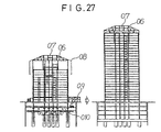
- the method shown in FIG. 27 is called a push-up method in which after a roof 06 and a top floor 07 are completed, they are raised (jacked up) by using hydraulic equipment etc. to produce a space for installing the next floor under the top floor 07, the next floor to be connected to the top floor 07 is built in this space, the roof 06 and the top floor 07 is lowered (jacked down) to incorporate with the lower floor, and the incorporated structure is jacked up to produce a space for installing the next floor under the incorporated structure, thus the building structure is assembled successively.
- reference numeral 08 denotes an external protective cover
- 09 denotes a material carrying unit
- 010 denotes a slide strut.
- An object of the present invention is to provide a module construction method in a steel structure building zone which solves the above problems with the conventional methods.
- a block can be carried in from one direction and joining and lifting by jacking up can be performed for the steel structure of any shape. Therefore, work can be done up to the maximum limit of jack capacity without being restricted.
- a steel structure can be constructed by being divided into zones, work can be done independently for each zone. If a trouble occurs or the progress of work is behind schedule in one zone, the work in other zones is not affected.
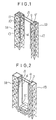
- Truss column assemblies 1A and 1B each of which is assembled by a plurality of pillars 13, beams 10, and horizontal braces 11 of a single item or a block, and vertical braces 15 in FIG. 3, described later, are erected by a crane (not shown). The floors in the truss column assemblies 1A and 1B and the contents on the floors are incorporated at an appropriate time in this erection process.
- the truss column assemblies 1A and 1B are assembled up to the top floor, and then a connecting passage 8, which is also used for adjusting the span, is installed at the upper part of these two truss column assemblies 1A and 1B.
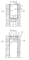
- hydraulic jacks 3 are installed at the upper part on the opposite side of the truss column assembly 1A, 1B. Also, jack rods 4, each of which is driven by the hydraulic jack 3, a first elevating device, are hung from core steel frames 9 on the opposite side of each of the truss column assemblies 1A and 1B.
- a truss beam assembly 1C which is formed by connecting a plurality of beam members 14 by using vertical braces 15 and horizontal braces 11, is carried in between the truss column assemblies 1A and 1B, and the jack rods 4 are connected to a temporary support frame 2 installed on top of the truss beam assembly 1C.
- the truss beam assembly 1C together with the temporary support frame 2 is jacked up to the top of the truss column assemblies 1A and 1B by the jack rods 4 driven by the jacks 3. After that, both ends of the truss beam assembly 1C are joined to the truss column assemblies 1A and 1B to form a gate-shaped truss assembly 1D.
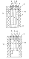
- a top block 6A which has been assembled including a floor, walls, and contents as a first structure block located at a high place, is carried in between the truss column assemblies 1A and 1B, and connected to the jack rods 4.
- the top block 6A has a heavy weight and a long span, an appropriate number of jacks 3 and jack rods 4 are installed on the temporary support frame 2, which is temporarily welded onto the truss beam assembly 1C as shown in the figure to be used for jacking up the truss beam assembly 1C.
- the top block 6A is jacked up to a height at which there is no interference in carrying in the next block 6B located just under the top block 6A.
- the next block 6B is carried in between the truss column assemblies 1A and 1B.
- the jack rods 4 are jacked down to allow the top block 6A to rest on the block 6B, and both blocks are connected by connecting hardware (not shown) to form one unit.
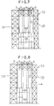
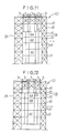
- all blocks arranged between the truss column assemblies 1A and 1B are assembled as one unit, all blocks are jacked up as shown in FIG. 12. All blocks are raised until the floors in the truss column assemblies 1A and 1B coincides with the corresponding floors in the blocks, and the beam 10 and the horizontal brace 11 of each floor are aligned.
- jacking up is performed excessively, and lower short pillars 5 are installed under the lowermost block. Jacking down is performed until the lower short pillars 5 are subjected to a load to some extent, and the beam 10 and the horizontal brace 11 of each floor are aligned.
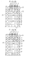
- upper short pillars 7 may be installed over the top block 6A as shown in FIG. 15. After the assembly of the gate-shaped truss assembly 1D and blocks 6A to 6C arranged between the truss column assemblies 1A and 1B is completed, the connecting passage 8, the temporary support frame 2, and jack rods 4 are removed.
- a central room floor 12 which is installed between two gate-shaped truss assemblies arranged in opposition, can be carried in as a module from any direction of four sides depending on the carrying-in entrance.
- the carrying-in and installation of these modules can be performed by the same procedure as that for the installation of the blocks 6A, 6B, and 6C between the truss column assemblies 1A and 1B.
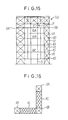
- the gate-shaped truss assemblies 1D are installed to fit in with the shape of the steel structure to be constructed, for example, as shown in FIGS. 16 and 17.
- a plurality of first elevating devices consisting of the jacks 3 and the jack rods 4 are arranged as shown in FIG. 18.
- the gate-shaped truss assembly 1D in the direction convenient for carrying-in should be one which has no blocks between the truss column assemblies 1A and 1B shown in FIG. 4 in accordance with the place where the steel structure is constructed.
- the gate-shaped truss assembly 1D which is at right angles to the above truss assembly and to which jacks 3 and jack rods 4 are mounted can incorporate all blocks under the gate-shaped truss assembly 1D shown in FIG. 15 and is reinforced.
- both side ends of the first module consisting of the floor 12 etc. of the top floor on which carried-in members, equipment, and apparatuses between the gate-shaped truss assemblies 1D are connected, as shown in FIG. 5, to jack rods 4 hung from the tops of opposed gate-shaped truss assemblies 1D.
- a frame similar to the temporary support frame 2 may be installed on top of the first module so that the jack rods 4 are connected to this frame.
- jacks 3 and jack rods 4 are driven simultaneously to lift the first module while keeping the horizontality of the module, like the case shown in FIG. 6, up to the height such that a second module located just under the first module can be carried in with a height margin.
- the second module is carried in just under the first module, or the second module is assembled by using members, equipment, and apparatuses carried in just under the first module.
- the first module which has been jacked up with margin, is jacked down and placed on the second module.
- the second module is joined to the first module for integration like the case shown in FIG. 8.
- the integrated first and second modules are jacked up, like the case shown in FIG.
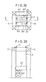
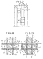
- FIGS. 19 to 21 show embodiments of a case where the construction zone formed between the gate-shaped truss assemblies 1D is wide and the module is too large, or the case where the weight of module is too heavy.
- the module installation work is performed as described below.
- Permanent support beams 20 are lifted between the gate-shaped truss assemblies 1D arranged in opposition by using the first elevating device provided at the side of the gate-shaped truss assembly 1D, and both ends of the support beam 20 are joined to the sides of the truss assemblies 1C.
- a module housed in the construction zone between the gate-shaped truss assemblies is divided into a plurality of modules (for example, M1 to M4) on a flat surface, and the divided modules are lifted by a second elevating device (jacks 3, jack rods 4) provided on each permanent support beam.
- a second elevating device jacks 3, jack rods 4
- jacks 3, jack rods 4 provided on each permanent support beam.
- new gate-shaped truss assemblies 1D' are constructed on the outside of the gate-shaped truss assemblies 1D between which modules have been assembled, to fit in with the shape and height of the steel structure, and modules are assembled between the opposed gate-shaped truss assemblies 1D', by which a required steel structure can be completed.
- FIG. 23 shows an installation procedure in constructing a cross-shaped steel structure.
- the installation sequence may be A, B, C, D, and E.
- the truss column assemblies a to 1 are erected in advance to fit in with the shape of the steel structure, and then a truss beam assembly 1C is installed between the tops of the adjacent truss column assemblies 1A and 1B to form a gate-shaped truss assembly.
- modules in B, A, C or D, A, E construction zones are installed, and then modules in D, E or B, C construction zones are assembled.
- FIG. 24 shows an example in which the truss column assembly at the central portion is of a hexagonal shape, and rhombic truss column assemblies are installed surrounding the central truss column assembly to construct a steel structure.
- FIG. 25 shows a steel structure in which three rhombic truss column assemblies are installed outside the steel structure shown in FIG. 24 to provide a three-direction projecting structure.
- the module construction method in a steel structure building zone is useful for assembly and construction work of a steel building in the case where the steel structure is very large, or there is no place where module is made block in advance because of limited work space, and also suitable for assembly and installation work of power generating sets, various steel making machines and paper making machines, and equipment and apparatuses for various chemical plants etc. which are installed the building.
Landscapes
- Engineering & Computer Science (AREA)
- Architecture (AREA)
- Physics & Mathematics (AREA)
- Electromagnetism (AREA)
- Civil Engineering (AREA)
- Structural Engineering (AREA)
- Conveying And Assembling Of Building Elements In Situ (AREA)
Claims (5)
- Procédé de construction de module dans une zone de construction de structure métallique applicable à la construction d'une structure métallique ou d'un bâtiment métallique, comprenant les opérations consistant à :ériger des assemblages de colonne d'armature (1A, 1B) formés en mettant en place et en joignant une pluralité de piliers;installer un assemblage de poutre d'armature (1C) entre les sommets desdits deux assemblages de colonne d'armature (1A, 1B) érigés en parallèle pour construire un assemblage d'armature en forme de porte (1D);installer des assemblages d'armature en forme de porte (1D) en opposition pour s'emboíter dans la forme plane de ladite structure métallique à construire; etinstaller des modules (12) dans la zone de construction formée entre lesdits assemblages d'armature en forme de porte (1D) en répétant un processus dans lequel, parmi des modules à installer dans la zone de construction formée entre des assemblages d'armature en forme de porte, un premier module (12) à mettre en place dans un endroit élevé est soulevé à la hauteur voulue en utilisant un premier dispositif élévateur (3, 4) installé à la partie supérieure sur le côté d'un assemblage d'armature en forme de porte, et un deuxième module est introduit juste en dessous du premier module pour intégrer les deux modules.
- Procédé de construction de module dans une zone de construction de structure métallique selon la revendication 1, dans lequel est ajoutée après l'opération consistant à installer des assemblages d'armature en forme de porte en opposition l'opération consistant à :soulever des poutres de support permanent (20) entre les assemblages d'armature en forme de porte (lD) disposés en opposition en utilisant les premiers dispositifs élévateur (3, 4) installés à la partie supérieure sur le côté des assemblages d'armature en forme de porte (1D), et joindre les deux extrémités de la poutre de support permanent (20) aux côtés des assemblages d'armature de poutre (1C).
- Procédé de construction de module dans une zone de construction de structure métallique selon la revendication 1 ou 2, dans lequel une opération est'ajoutée dans laquelle des blocs de structure (6A, 6B, 6C) sont installés dans la zone de construction sous un assemblage d'armature en forme de porte (1D) en répétant un processus dans lequel, parmi les blocs de structure à loger dans la zone de construction formée sous un assemblage d'armature en forme de porte, un premier bloc de structure (6A) à mettre en place dans un endroit élevé est soulevé à la hauteur voulue en utilisant ledit premier dispositif élévateur (3, 4), et un deuxième bloc de structure (6B) est introduit juste en dessous du premier bloc de structure (6A) pour intégrer les deux blocs.
- Procédé de construction de module dans une zone de construction de structure métallique selon la revendication 3, dans lequel une opération est ajoutée dans laquelle après que l'un desdits modules (12) ou blocs de structure (6A, 6B, 6C), qui sont préfabriqués de telle façon que leurs tailles soient égales entre elles, a été installé dans la zone de construction, alors l'autre (module ou bloc de structure) est joint à des poutres et des croisillons horizontaux (11) à installer dans le même étage.
- Procédé de construction de module dans une zone de construction de structure métallique selon la revendication 3, dans lequel l'opération servant à installer des modules (12) dans la zone de construction et l'opération servant à installer des blocs de structure (6A, 6B, 6C) est effectuée indépendamment en termes de temps.
Applications Claiming Priority (5)
| Application Number | Priority Date | Filing Date | Title |
|---|---|---|---|
| JP113072/93 | 1993-05-14 | ||
| JP11307293 | 1993-05-14 | ||
| JP1603/94 | 1994-01-12 | ||
| JP6001603A JP2576035B2 (ja) | 1993-05-14 | 1994-01-12 | 鉄鋼構造物建設用ゾーンモジュール工法 |
| PCT/JP1994/000777 WO1994027003A1 (fr) | 1993-05-14 | 1994-05-13 | Procede d'assemblage de modules de zone d'une construction a structure en acier |
Publications (3)
| Publication Number | Publication Date |
|---|---|
| EP0654571A1 EP0654571A1 (fr) | 1995-05-24 |
| EP0654571A4 EP0654571A4 (fr) | 1996-06-05 |
| EP0654571B1 true EP0654571B1 (fr) | 1999-04-14 |
Family
ID=26334855
Family Applications (1)
| Application Number | Title | Priority Date | Filing Date |
|---|---|---|---|
| EP94914616A Expired - Lifetime EP0654571B1 (fr) | 1993-05-14 | 1994-05-13 | Procede d'assemblage de modules de zone d'une construction a structure en acier |
Country Status (6)
| Country | Link |
|---|---|
| US (1) | US5577362A (fr) |
| EP (1) | EP0654571B1 (fr) |
| JP (1) | JP2576035B2 (fr) |
| DE (1) | DE69417849T2 (fr) |
| ES (1) | ES2132402T3 (fr) |
| WO (1) | WO1994027003A1 (fr) |
Cited By (2)
| Publication number | Priority date | Publication date | Assignee | Title |
|---|---|---|---|---|
| CN106121081A (zh) * | 2016-08-29 | 2016-11-16 | 山东莱钢建设有限公司 | 竖向桁架及建筑钢结构总成 |
| CN106368438A (zh) * | 2016-11-16 | 2017-02-01 | 上海通用金属结构工程有限公司 | 一种钢结构厂房屋面施工方法 |
Families Citing this family (50)
| Publication number | Priority date | Publication date | Assignee | Title |
|---|---|---|---|---|
| JP3413584B2 (ja) * | 1995-04-04 | 2003-06-03 | 清水建設株式会社 | 架構構造物の施工方法 |
| NL1000358C2 (en) * | 1995-05-12 | 1996-11-13 | D3Bn Adviesbureau Civ Ing | Multi-floor-building erection system |
| EP1026480B1 (fr) | 1999-02-05 | 2017-03-29 | Endress + Hauser Flowtec AG | Débitmètre volumique ou massique |
| US6343445B1 (en) | 2000-03-07 | 2002-02-05 | General Signal Corporation | Tower structure |
| JP2002098304A (ja) * | 2000-09-21 | 2002-04-05 | Ishikawajima Harima Heavy Ind Co Ltd | ボイラ架構建造工法 |
| CN100427690C (zh) * | 2004-03-18 | 2008-10-22 | 上海市机械施工有限公司 | 大跨度大纵深空间钢结构的矩阵式顶推安装法 |
| DE102005023488B4 (de) * | 2005-05-21 | 2009-12-03 | Plauen Stahl Technologie Gmbh | Hubverfahren zur taktweisen Errichtung eines Gerüstes für hängende Kessel |
| JP2007107789A (ja) * | 2005-10-12 | 2007-04-26 | Babcock Hitachi Kk | ボイラ設備の据付工法 |
| JP5059357B2 (ja) * | 2006-08-03 | 2012-10-24 | 株式会社日立プラントテクノロジー | ボイラケージ部フロアの構築方法 |
| JP2008280677A (ja) * | 2007-05-08 | 2008-11-20 | Ohbayashi Corp | 吊構造建物の構築方法、吊構造建物 |
| CN102277900B (zh) * | 2011-05-06 | 2013-03-06 | 河海大学 | 宝瓶形空间钢结构的分段累积顶升安装方法 |
| KR102057346B1 (ko) | 2011-06-28 | 2019-12-18 | 디에스엠 아이피 어셋츠 비.브이. | 모듈형 다층 생산 플랜트 및 그 건축 방법 |
| CN102953556B (zh) * | 2012-11-14 | 2016-05-18 | 中冶天工集团有限公司 | 大跨度不对称矩形空间扭曲管桁架的吊装方法 |
| CN103046758B (zh) * | 2013-01-18 | 2015-04-15 | 上海建工一建集团有限公司 | 多道区间承力巨型桁架门式结构施工方法 |
| CN103243930B (zh) * | 2013-04-23 | 2015-02-25 | 重庆大学 | 超高层钢结构模块化施工系统及其方法 |
| CN103266778B (zh) * | 2013-05-08 | 2015-06-10 | 北京城建精工钢结构工程有限公司 | 可拆三角形胎架及钢桁架拼装施工方法 |
| JP2015101921A (ja) * | 2013-11-27 | 2015-06-04 | 三菱日立パワーシステムズ株式会社 | 鉄骨建屋、プラント及び鉄骨建屋の組み立て方法 |
| JP6417606B2 (ja) * | 2014-04-30 | 2018-11-07 | 三菱日立パワーシステムズ株式会社 | コンバインドサイクルプラント、及びそのプラント建屋 |
| CN104060841B (zh) * | 2014-07-04 | 2016-06-29 | 中国建筑第八工程局有限公司 | 大跨度钢梁安装施工方法 |
| CN104234187A (zh) * | 2014-08-20 | 2014-12-24 | 中亿丰建设集团股份有限公司 | 办公楼大桁架钢结构及其安装方法 |
| CN105484517A (zh) * | 2014-09-18 | 2016-04-13 | 沈阳铝镁设计研究院有限公司 | 厂房原有屋面梁下新增钢梁连接结构 |
| CN104452963B (zh) * | 2014-11-02 | 2017-04-19 | 中国水利水电第四工程局有限公司 | 一种钢网架关键部件制作及施工方法 |
| CN104328922B (zh) * | 2014-11-13 | 2016-05-18 | 中铁六局集团有限公司 | 高空多层悬垂钢结构逆做法吊装施工技术 |
| CN105421792A (zh) * | 2015-12-15 | 2016-03-23 | 安徽伟宏钢结构集团股份有限公司 | 一种模块式钢结构构件的吊装施工工艺 |
| CN106078195B (zh) * | 2016-06-27 | 2018-07-06 | 宝鸡石油机械有限责任公司 | 箱块式底座的组装方法 |
| CN106006301B (zh) * | 2016-07-27 | 2018-01-16 | 中建一局集团建设发展有限公司 | 一种超高层施工电梯高空转换辅助装置及施工方法 |
| CN107781505A (zh) * | 2016-08-27 | 2018-03-09 | 中国二十冶集团有限公司 | 架空管道的集成化安装方法 |
| CN106337564A (zh) * | 2016-08-30 | 2017-01-18 | 上海二十冶建设有限公司 | 高空超大悬挑钢结构无支撑施工方法 |
| CN106760624A (zh) * | 2016-12-08 | 2017-05-31 | 中建钢构有限公司 | 一种用于支撑大跨度单层网壳结构的支撑胎架 |
| CN107060105B (zh) * | 2017-05-10 | 2018-11-13 | 中国建筑第二工程局有限公司 | 一种塔楼间多个钢连廊的提升施工方法 |
| US11248388B2 (en) * | 2019-05-20 | 2022-02-15 | Ctb, Inc. | Commercial hopper grain bin assembly method |
| CN110359548A (zh) * | 2019-07-18 | 2019-10-22 | 合肥工业大学 | 一种钢桁架悬挂混合系统及施工方法 |
| CN112878500A (zh) * | 2019-11-29 | 2021-06-01 | 中冶(上海)钢结构科技有限公司 | 一种混凝土泵管可循环利用的顶升施工方法 |
| DE102020206194A1 (de) * | 2020-05-18 | 2021-11-18 | Gebhardt Fördertechnik GmbH | Verfahren zur Errichtung eines Aufzugs und Aufzug |
| CN112709448A (zh) * | 2020-12-22 | 2021-04-27 | 北京首钢建设集团有限公司 | 一种受限空间内管桁架累积滑移施工方法 |
| CN113136961A (zh) * | 2021-03-25 | 2021-07-20 | 中国建筑第八工程局有限公司 | 用于大跨度桁架的提升结构及其提升方法 |
| CN112982683B (zh) * | 2021-05-20 | 2021-08-17 | 中铁建工集团有限公司 | 一种屋面钢结构施工方法及系统 |
| CN113431399A (zh) * | 2021-06-21 | 2021-09-24 | 五冶集团上海有限公司 | 一种皮带机通廊模块化安装方法 |
| CN113503047A (zh) * | 2021-07-31 | 2021-10-15 | 中冶(上海)钢结构科技有限公司 | 钢结构提升过程中牵引调整高空位置偏移的方法 |
| CN113666242B (zh) * | 2021-08-08 | 2024-05-24 | 中国飞机强度研究所 | 一种气候环境试验喷淋架模块化吊装方法 |
| CN113622576B (zh) * | 2021-09-08 | 2022-11-25 | 中国建筑第四工程局有限公司 | 一种超大型体育场馆钢罩棚屋盖结构空间转体施工方法 |
| CN114215191B (zh) * | 2022-02-23 | 2022-05-24 | 北京建工集团有限责任公司 | 超大跨度钢屋盖模块化吊装、两阶段整体同步提升方法 |
| CN114776035B (zh) * | 2022-06-21 | 2022-09-13 | 北京市建筑工程研究院有限责任公司 | 一种斜交轮辐式索桁架结构的施工方法 |
| CN115874814B (zh) * | 2022-11-29 | 2025-09-05 | 五冶集团上海有限公司 | 一种热回收焦炉管道桁架的模块化安装方法 |
| CN116479773B (zh) * | 2023-04-20 | 2026-04-21 | 中建二局第二建筑工程有限公司 | 高架平台钢结构施工方法 |
| CN116971481B (zh) * | 2023-06-26 | 2026-03-10 | 中铁钢结构有限公司 | 一种大跨度场馆钢结构及其建造工艺 |
| CN117536449A (zh) * | 2023-11-03 | 2024-02-09 | 中铁四局集团有限公司 | 一种大跨度桁架的组装方法 |
| CN118601133B (zh) * | 2024-05-22 | 2025-10-14 | 中国建筑第二工程局有限公司 | 一种钢结构连廊分层提升及高空拼装的施工方法 |
| CN119062005B (zh) * | 2024-08-31 | 2025-10-21 | 中冶建工集团有限公司 | 用于7字型悬臂管桁架安装的施工方法 |
| CN121273102A (zh) * | 2025-09-17 | 2026-01-06 | 中建钢构股份有限公司 | 一种组合式钢结构建筑的施工方法 |
Family Cites Families (11)
| Publication number | Priority date | Publication date | Assignee | Title |
|---|---|---|---|---|
| FR1454043A (fr) * | 1965-08-20 | 1966-07-22 | Groupe Pour L Etude D Une Arch | Procédé pour la construction de l'ossature de bâtiments métalliques |
| GB1293689A (en) * | 1969-12-23 | 1972-10-18 | Alan Charles Whitting | Improvements in or relating to methods of building |
| US3863418A (en) * | 1972-01-11 | 1975-02-04 | Fresa Liechtenstein Ets | Building method |
| FR2214019A1 (fr) * | 1973-01-16 | 1974-08-09 | Six Jean | |
| JPS5226044B2 (fr) * | 1973-07-19 | 1977-07-12 | ||
| JPS5226044A (en) * | 1975-08-23 | 1977-02-26 | Ohbayashigumi Ltd | Half wet cooling tower |
| JPS6047141A (ja) * | 1983-08-25 | 1985-03-14 | 株式会社大林組 | 中高層建築における水まわり設備スペ−スの施工法 |
| JPH0326262A (ja) * | 1989-06-23 | 1991-02-04 | Toto Ltd | 気泡量を調節可能な気泡発生浴槽 |
| JP2687708B2 (ja) * | 1990-10-25 | 1997-12-08 | 株式会社大林組 | 高層ビルの建設方法 |
| JPH086897B2 (ja) * | 1991-02-08 | 1996-01-29 | 三菱重工業株式会社 | 吊下型ボイラの据付工法 |
| JP2513376B2 (ja) * | 1991-07-25 | 1996-07-03 | 鹿島建設株式会社 | 建屋の構築方法 |
-
1994
- 1994-01-12 JP JP6001603A patent/JP2576035B2/ja not_active Expired - Lifetime
- 1994-05-13 EP EP94914616A patent/EP0654571B1/fr not_active Expired - Lifetime
- 1994-05-13 ES ES94914616T patent/ES2132402T3/es not_active Expired - Lifetime
- 1994-05-13 DE DE69417849T patent/DE69417849T2/de not_active Expired - Fee Related
- 1994-05-13 WO PCT/JP1994/000777 patent/WO1994027003A1/fr not_active Ceased
- 1994-05-13 US US08/367,249 patent/US5577362A/en not_active Expired - Lifetime
Cited By (2)
| Publication number | Priority date | Publication date | Assignee | Title |
|---|---|---|---|---|
| CN106121081A (zh) * | 2016-08-29 | 2016-11-16 | 山东莱钢建设有限公司 | 竖向桁架及建筑钢结构总成 |
| CN106368438A (zh) * | 2016-11-16 | 2017-02-01 | 上海通用金属结构工程有限公司 | 一种钢结构厂房屋面施工方法 |
Also Published As
| Publication number | Publication date |
|---|---|
| EP0654571A1 (fr) | 1995-05-24 |
| ES2132402T3 (es) | 1999-08-16 |
| DE69417849D1 (de) | 1999-05-20 |
| US5577362A (en) | 1996-11-26 |
| EP0654571A4 (fr) | 1996-06-05 |
| DE69417849T2 (de) | 1999-10-07 |
| WO1994027003A1 (fr) | 1994-11-24 |
| JPH0726726A (ja) | 1995-01-27 |
| JP2576035B2 (ja) | 1997-01-29 |
Similar Documents
| Publication | Publication Date | Title |
|---|---|---|
| US5577362A (en) | Module construction method in a steel structure building zone | |
| CA1329633C (fr) | Appareil et methode de construction | |
| KR102584877B1 (ko) | 선조립 철골 구조물의 하중 분산형 실내 리프팅 장비 및 이를 이용한 선조립 철골 구조물의 설치방법 | |
| CN114000426A (zh) | 索塔及其施工工艺 | |
| KR102133182B1 (ko) | 악세스플로어의 모듈화 시공방법 | |
| JPH0932349A (ja) | 建築物の施工方法 | |
| CN118531991A (zh) | 一种高空作业平台及其施工方法 | |
| US4679374A (en) | Building construction method | |
| JP2008214932A (ja) | 建物の構築方法 | |
| JPH08239906A (ja) | 建物の構築工法 | |
| KR102623001B1 (ko) | 선조립 철골 구조물의 양중용 이중 프레임 구조체 및 이를 포함하는 선조립 철골 구조물의 하중 분산형 실내 리프팅 장비 | |
| EP0265446B1 (fr) | Procede de construction de modules de dimensions importantes | |
| CN219341464U (zh) | 一种反力墙及反力台座加载孔模块运输保护装置 | |
| JP3225455B2 (ja) | 建屋の構築方法 | |
| JPH04118438A (ja) | 建築物の施工方法およびその装置 | |
| JP2796448B2 (ja) | ビルの建設方法と同建設方法に使用されるビルの建設装置 | |
| JP2778842B2 (ja) | ビルの建設方法 | |
| JP3416759B2 (ja) | 地下構造物の躯体構築装置 | |
| JPH10102779A (ja) | 重量物昇降機の組立方法及びその装置 | |
| JPH11131811A (ja) | 建物の建築方法 | |
| JP2884398B2 (ja) | 建物構造体の建築工法及び建物構造体の扛重装置 | |
| JP2761527B2 (ja) | 構造物の構築方法 | |
| JP2008215013A (ja) | 建物の構築方法 | |
| JPH04336167A (ja) | ビルの建設方法と同建設方法に使用する昇降装置 | |
| JPS5830979B2 (ja) | 大張間架溝の建方工法 |
Legal Events
| Date | Code | Title | Description |
|---|---|---|---|
| PUAI | Public reference made under article 153(3) epc to a published international application that has entered the european phase |
Free format text: ORIGINAL CODE: 0009012 |
|
| 17P | Request for examination filed |
Effective date: 19950104 |
|
| AK | Designated contracting states |
Kind code of ref document: A1 Designated state(s): DE ES FR GB IT |
|
| A4 | Supplementary search report drawn up and despatched | ||
| AK | Designated contracting states |
Kind code of ref document: A4 Designated state(s): DE ES FR GB IT |
|
| 17Q | First examination report despatched |
Effective date: 19970707 |
|
| GRAG | Despatch of communication of intention to grant |
Free format text: ORIGINAL CODE: EPIDOS AGRA |
|
| GRAG | Despatch of communication of intention to grant |
Free format text: ORIGINAL CODE: EPIDOS AGRA |
|
| GRAH | Despatch of communication of intention to grant a patent |
Free format text: ORIGINAL CODE: EPIDOS IGRA |
|
| GRAH | Despatch of communication of intention to grant a patent |
Free format text: ORIGINAL CODE: EPIDOS IGRA |
|
| GRAA | (expected) grant |
Free format text: ORIGINAL CODE: 0009210 |
|
| AK | Designated contracting states |
Kind code of ref document: B1 Designated state(s): DE ES FR GB IT |
|
| ITF | It: translation for a ep patent filed | ||
| REF | Corresponds to: |
Ref document number: 69417849 Country of ref document: DE Date of ref document: 19990520 |
|
| ET | Fr: translation filed | ||
| REG | Reference to a national code |
Ref country code: ES Ref legal event code: FG2A Ref document number: 2132402 Country of ref document: ES Kind code of ref document: T3 |
|
| PLBE | No opposition filed within time limit |
Free format text: ORIGINAL CODE: 0009261 |
|
| STAA | Information on the status of an ep patent application or granted ep patent |
Free format text: STATUS: NO OPPOSITION FILED WITHIN TIME LIMIT |
|
| 26N | No opposition filed | ||
| REG | Reference to a national code |
Ref country code: GB Ref legal event code: IF02 |
|
| PGFP | Annual fee paid to national office [announced via postgrant information from national office to epo] |
Ref country code: FR Payment date: 20040510 Year of fee payment: 11 |
|
| PGFP | Annual fee paid to national office [announced via postgrant information from national office to epo] |
Ref country code: GB Payment date: 20040512 Year of fee payment: 11 |
|
| PGFP | Annual fee paid to national office [announced via postgrant information from national office to epo] |
Ref country code: ES Payment date: 20040518 Year of fee payment: 11 |
|
| PG25 | Lapsed in a contracting state [announced via postgrant information from national office to epo] |
Ref country code: IT Free format text: LAPSE BECAUSE OF NON-PAYMENT OF DUE FEES;WARNING: LAPSES OF ITALIAN PATENTS WITH EFFECTIVE DATE BEFORE 2007 MAY HAVE OCCURRED AT ANY TIME BEFORE 2007. THE CORRECT EFFECTIVE DATE MAY BE DIFFERENT FROM THE ONE RECORDED. Effective date: 20050513 Ref country code: GB Free format text: LAPSE BECAUSE OF NON-PAYMENT OF DUE FEES Effective date: 20050513 |
|
| PG25 | Lapsed in a contracting state [announced via postgrant information from national office to epo] |
Ref country code: ES Free format text: LAPSE BECAUSE OF NON-PAYMENT OF DUE FEES Effective date: 20050514 |
|
| GBPC | Gb: european patent ceased through non-payment of renewal fee |
Effective date: 20050513 |
|
| PG25 | Lapsed in a contracting state [announced via postgrant information from national office to epo] |
Ref country code: FR Free format text: LAPSE BECAUSE OF NON-PAYMENT OF DUE FEES Effective date: 20060131 |
|
| REG | Reference to a national code |
Ref country code: FR Ref legal event code: ST Effective date: 20060131 |
|
| REG | Reference to a national code |
Ref country code: ES Ref legal event code: FD2A Effective date: 20050514 |
|
| PGFP | Annual fee paid to national office [announced via postgrant information from national office to epo] |
Ref country code: DE Payment date: 20070510 Year of fee payment: 14 |
|
| PG25 | Lapsed in a contracting state [announced via postgrant information from national office to epo] |
Ref country code: DE Free format text: LAPSE BECAUSE OF NON-PAYMENT OF DUE FEES Effective date: 20081202 |