EP0654677A1 - Procédé et dispositif pour traiter un signal - Google Patents
Procédé et dispositif pour traiter un signal Download PDFInfo
- Publication number
- EP0654677A1 EP0654677A1 EP94308632A EP94308632A EP0654677A1 EP 0654677 A1 EP0654677 A1 EP 0654677A1 EP 94308632 A EP94308632 A EP 94308632A EP 94308632 A EP94308632 A EP 94308632A EP 0654677 A1 EP0654677 A1 EP 0654677A1
- Authority
- EP
- European Patent Office
- Prior art keywords
- signal
- calculated
- parameters
- calculating
- contribution
- Prior art date
- Legal status (The legal status is an assumption and is not a legal conclusion. Google has not performed a legal analysis and makes no representation as to the accuracy of the status listed.)
- Withdrawn
Links
- 238000000034 method Methods 0.000 title claims abstract description 45
- 238000012545 processing Methods 0.000 title claims abstract description 18
- 238000005314 correlation function Methods 0.000 claims description 54
- 230000006870 function Effects 0.000 claims description 27
- 238000010606 normalization Methods 0.000 claims description 3
- 230000001902 propagating effect Effects 0.000 claims 2
- 230000008054 signal transmission Effects 0.000 claims 2
- 238000007796 conventional method Methods 0.000 description 10
- 238000004364 calculation method Methods 0.000 description 5
- 238000004891 communication Methods 0.000 description 5
- 238000005070 sampling Methods 0.000 description 4
- 238000013459 approach Methods 0.000 description 3
- 230000010354 integration Effects 0.000 description 3
- 230000005540 biological transmission Effects 0.000 description 2
- 238000010276 construction Methods 0.000 description 2
- 230000003247 decreasing effect Effects 0.000 description 2
- 230000003111 delayed effect Effects 0.000 description 2
- 230000000694 effects Effects 0.000 description 2
- 238000007476 Maximum Likelihood Methods 0.000 description 1
- 238000002940 Newton-Raphson method Methods 0.000 description 1
- 238000004458 analytical method Methods 0.000 description 1
- 230000001174 ascending effect Effects 0.000 description 1
- 230000001427 coherent effect Effects 0.000 description 1
- 230000001934 delay Effects 0.000 description 1
- 230000002452 interceptive effect Effects 0.000 description 1
- 239000011159 matrix material Substances 0.000 description 1
- 230000000306 recurrent effect Effects 0.000 description 1
Images


Classifications
-
- H—ELECTRICITY
- H04—ELECTRIC COMMUNICATION TECHNIQUE
- H04B—TRANSMISSION
- H04B7/00—Radio transmission systems, i.e. using radiation field
- H04B7/005—Control of transmission; Equalising
-
- G—PHYSICS
- G01—MEASURING; TESTING
- G01S—RADIO DIRECTION-FINDING; RADIO NAVIGATION; DETERMINING DISTANCE OR VELOCITY BY USE OF RADIO WAVES; LOCATING OR PRESENCE-DETECTING BY USE OF THE REFLECTION OR RERADIATION OF RADIO WAVES; ANALOGOUS ARRANGEMENTS USING OTHER WAVES
- G01S19/00—Satellite radio beacon positioning systems; Determining position, velocity or attitude using signals transmitted by such systems
- G01S19/01—Satellite radio beacon positioning systems transmitting time-stamped messages, e.g. GPS [Global Positioning System], GLONASS [Global Orbiting Navigation Satellite System] or GALILEO
- G01S19/13—Receivers
- G01S19/22—Multipath-related issues
-
- H—ELECTRICITY
- H04—ELECTRIC COMMUNICATION TECHNIQUE
- H04B—TRANSMISSION
- H04B1/00—Details of transmission systems, not covered by a single one of groups H04B3/00 - H04B13/00; Details of transmission systems not characterised by the medium used for transmission
- H04B1/69—Spread spectrum techniques
- H04B1/707—Spread spectrum techniques using direct sequence modulation
- H04B1/7097—Interference-related aspects
- H04B1/711—Interference-related aspects the interference being multi-path interference
-
- H—ELECTRICITY
- H04—ELECTRIC COMMUNICATION TECHNIQUE
- H04B—TRANSMISSION
- H04B1/00—Details of transmission systems, not covered by a single one of groups H04B3/00 - H04B13/00; Details of transmission systems not characterised by the medium used for transmission
- H04B1/69—Spread spectrum techniques
- H04B1/707—Spread spectrum techniques using direct sequence modulation
- H04B1/709—Correlator structure
-
- H—ELECTRICITY
- H04—ELECTRIC COMMUNICATION TECHNIQUE
- H04B—TRANSMISSION
- H04B1/00—Details of transmission systems, not covered by a single one of groups H04B3/00 - H04B13/00; Details of transmission systems not characterised by the medium used for transmission
- H04B1/69—Spread spectrum techniques
- H04B1/707—Spread spectrum techniques using direct sequence modulation
- H04B1/7097—Interference-related aspects
- H04B1/711—Interference-related aspects the interference being multi-path interference
- H04B1/7115—Constructive combining of multi-path signals, i.e. RAKE receivers
- H04B1/712—Weighting of fingers for combining, e.g. amplitude control or phase rotation using an inner loop
-
- H—ELECTRICITY
- H04—ELECTRIC COMMUNICATION TECHNIQUE
- H04B—TRANSMISSION
- H04B2201/00—Indexing scheme relating to details of transmission systems not covered by a single group of H04B3/00 - H04B13/00
- H04B2201/69—Orthogonal indexing scheme relating to spread spectrum techniques in general
- H04B2201/707—Orthogonal indexing scheme relating to spread spectrum techniques in general relating to direct sequence modulation
- H04B2201/70715—Orthogonal indexing scheme relating to spread spectrum techniques in general relating to direct sequence modulation with application-specific features
Definitions
- the present invention relates to a method and device for processing a signal, for use in communication systems or satellite navigation systems, for instance. More particularly, the present invention relates to a method and device for processing a signal wherein any errors caused by multipath are eliminated or at least reduced. In one particular embodiment, the present invention relates to a navigation system.
- communication from a transmitter to a receiver involves the transmission, by the transmitter, of a carrier wave signal which is coded by an information signal, such as by AM or FM, and the reception, by the receiver, of the coded signal.
- the received signal is decoded for obtaining the information therein.
- the propagation time of the signal i.e. the time which passes between the moment of transmission and the moment of reception, depends upon the distance between the transmitter and the receiver, and upon the propagation speed of the carrier wave signal, as is well known.
- the carrier wave signal reaches the receiver not only directly, i.e. via the line of sight, but also via one or more reflections from objects such as buildings, mountains, clouds, atmospheric layers, etc. Since the propagation path via reflection is always longer than the line of sight, the propagation time of the signal via reflection is always longer than the propagation time of the signal via the line of sight, i.e. a reflected signal always has a certain delay with respect to the direct signal.
- the receiver can not distinguish between the direct signal and a reflected signal, and the combination of the direct signal as received by the receiver and the reflected signals as received by the receiver is processed as if it were an undistorted signal; however, said combination obviously contains an error with respect to the signal as transmitted. This problem is commonly known as "multipath". Multipath can also be caused by diffraction.
- navigation is based on the principle of determining the distance between an object and a reference position by means of a communication signal.
- a reference station such as a satellite, emits a signal, which is received by a receiver associated with said object.
- the distance of the object to the reference station can be calculated.
- the distances of the object to a second and possibly further reference stations are calculated.
- the position of the reference station is constant and may be incorporated in the receiver as a constant value.
- the signal may contain information regarding the position of the reference station. Since, therefore, the positions of the reference stations are "known" by the receiver, it is thus possible to calculate the exact position of the object.
- GPS and LORAN-C navigation systems of the above-described type are known under the names GPS and LORAN-C. These systems are used, for instance, by ships at sea, and by aeroplanes in their approaching an airport.
- J.J. Spilker “Digital Communications by Satellite”, Prentice Hall, New Jersey, 1977; N. Ackroyd and R. Lorimer: “Global Navigation: A GPS User's Guide”, Lloyd's of London Press, London, 1990; B. Forsell: “Radio Navigation Systems", Prentice Hall, 1991, ISBN 0-13-751058-6.
- Fig.1 schematically shows a ship 1 at sea, and a satellite 2 emitting a signal 4.
- the satellite equipment for generating and emitting said signal is generally indicated at 3.
- the construction of the satellite equipment 3 does not form part of the invention, and knowledge of this construction is not necessary for understanding the present invention. Therefore, the satellite 2 and its satellite equipment 3 will not be discussed further. Suffice it to say that the satellite 2 may be a satellite as being used at present, such as the GPS satellites.
- Fig.2 schematically shows the shape of the navigation signal 5 as emitted by the equipment 3.
- the ordinate is the signal intensity I in arbitrary units
- the abscissa is the time t.
- the navigation signal 5 may have the form of a single pulse, such as is employed in the LORAN-C system (curve A), or the navigation signal 5 may have the form of a sequence of pulses (curve B), such as is employed in the GPS system.
- Fig.2 illustrates that the navigation signal 5 is emitted periodically, the period P being 1 ms in the above-mentioned systems. It is noted that the beginning of each signal period is emitted at moments t0 in time which are very accurately specified under control of a system clock.
- Curve A of fig.3 illustrates the GPS navigation signal 5 at a larger time scale, wherein only a first part of the signal is shown.
- the GPS navigation signal 5 constitutes a pseudo random noise code containing a predetermined number of code bits.
- the code bits are usually referred to as "chips". Each chip can have two possible values, namely +1 or -1. In the GPS system, said predetermined number is 1023. In the following, the individual chips will be referred to as C(1), C(2), ... C(1023).
- Each satellite 2 has its own characteristic code as defined by the set of values of C(1), C(2), ... C(1023).
- the receiver 10 aboard the ship 1 comprises at least one code generator, which can be set to generate a reference signal corresponding to the characteristic code of a specific satellite 2.
- the receiver 10 is equipped with a memory where information on the characteristic codes of a plurality of satellites is stored, so that an operator needs only to indicate which satellite he is interested in and the code generator of the receiver 10 will automatically generate a reference signal corresponding to the characteristic code of that specific satellite of interest (tuning the code generator).
- Figures 3 and 4 illustrate the principle of detecting the propagation time of the signal 4, which will be referred to as delay time ⁇ 0.
- curve A of fig.3 shows the navigation signal 5 as emitted by the satellite 2, i.e. the beginning of C(1) coincides with the beginning t0 of a time period. Therefore, curve A of fig.3 can also be considered a representation of the reference signal as generated by the code generator of the receiver 10.
- Curve B shows the navigation signal 5' as received at an input 11 of the receiver 10 (in the absence of noise and multipath), i.e. the beginning of C(1) being delayed by delay time ⁇ 0 with respect to t0. It is noted that in fig.3 the carrier wave and data are not shown.
- a control device (not shown) associated with the receiver 10 provides a local reference signal 6, which is identical to the reference signal 5 but shifted over a certain shift time ⁇ .
- This local reference signal 6 is shown in curve C of fig.3.
- said control device compares said local reference signal 6 with the navigation signal 5' as received at an input 11 of the receiver 10. More specifically, said control device performs a multiplication operation on the local reference signal 6 and the received navigation signal 5', i.e. the local reference signal 6 is multiplied point by point with the received navigation signal 5'. Subsequently, the resulting signal, which is shown in curve D of fig.3 and which will be referred to as multiplied signal 7, is averaged, i.e. the multiplied signal 7 is integrated over a sufficiently large time to provide a mean value M( ⁇ ) of the multiplied signal 7.
- the multiplied signal 7 can only take the values +1 or -1, depending on whether the values of the signals 6 and 5' are identical to each other or not, respectively. Therefore, the mean value M( ⁇ ) of the multiplied signal 7 will be a value between +1 and -1, too. Since the shape of the multiplied signal 7 depends on the shift time ⁇ , the exact value of M( ⁇ ) depends on the chosen value of the shift time ⁇ . Since the navigation signal 5 is a pseudo random code, said mean value M( ⁇ ) will be practically zero for most values of the shift time ⁇ , and will differ significantly from zero only if the shift time ⁇ approaches the delay time ⁇ 0.
- the exact shape of the correlation function 8 is known in advance, and depends on the specific code of the satellite in question. In curve E of fig.3, this shape is shown as being an ideal triangle.
- the width W of the triangle is a known constant value, for practical purposes equal to twice the duration of a chip; therefore, the correlation function 8 is fully determined by the coordinates ( ⁇ 0, M( ⁇ 0)) of its maximum.
- ⁇ 0 is the relevant parameter determining the position of the correlation function 8 with respect to the beginning of the time periods.
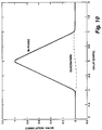
- the correlation function 8 is not an ideal triangle as shown in curve E of fig.3 but is more or less curved, as is shown in fig.10, depending on the characteristics of the receiver.
- the conventional method employed in conventional receivers for determining the propagation time ⁇ 0 is explained with reference to fig.4, which shows the correlation function 8 on a larger scale.
- the local reference signal 6 is generated for a first value t1 of the shift time ⁇ , and the corresponding mean value M(t1) of the multiplied signal 7 is calculated.
- the local reference signal 6 is generated for a second value t1+ ⁇ t of the shift time, and the corresponding mean value M(t1+ ⁇ t) of the multiplied signal 7 is calculated.
- the sample spacing, indicated as ⁇ t is a constant value.
- an error signal ⁇ 1 M(t1) - M(t1+ ⁇ t) is calculated.
- DLL Delay Locked Loop
- a serious disadvantage of this conventional method is that the calculated propagation time ⁇ 0 is not accurate enough, which is demonstrated with reference to fig.5, which illustrates the shape of a correlation function 23 which is a combination of a correlation function 24 for the navigation signal 5' as received via the line of sight and two correlation functions 25, 26 for the navigation signal 5' as received via reflection.
- the propagation times ⁇ 1 and ⁇ 2 of the reflection peaks 25, 26 are larger than the propagation time ⁇ 0 of the line of sight peak 24, and their respective maxima A1 and A2 are shown as being smaller than the maximum A0 of the line of sight peak 24.
- the widths W1 and W2 of the reflection peaks 25, 26 are substantially equal to the width W0 of the line of sight peak 24.
- the time ⁇ x calculated by the conventional method is not even an accurate estimate of the position of the maximum of the peak 23, because the peak 23 is not symmetrical in the presence of multipath.
- the present invention is based on mathematical insight in the actual shape of the navigation signal 5' and the correlation function 23 in the presence of multipath. Therefore, according to one aspect of the invention the influence of multipath is eliminated, or at least minimized, by measuring the complete shape of the correlation function 23 of the received navigation signal 5', calculating an estimate of the multipath-induced contribution and the line of sight contribution to said correlation function, and calculating the propagation time ⁇ 0 from the thus calculated line of sight contribution to said correlation function.
- p(t) is a function representing the navigation signal 5, which corresponds to the reference signal as stored in the memory of the receiver 10. It is assumed that there are M ac reflection signals (multipath) contributing to the correlation function 23 of the received navigation signal 5', and that each of said M ac reflection signals can be represented by the function x i (t) ⁇ a i ⁇ p(t- ⁇ i ) ⁇ cos( ⁇ t + ⁇ i ), wherein a i is the amplitude of a signal with index i; ⁇ i is the delay time of the signal with index i; ⁇ i is the phase of the signal with index i; ⁇ is the angular frequency of the carrier signal of the navigation signal.
- the actually received navigation signal 5' as received by the receiver 10 can be written as
- n(t) denotes a noise component.
- the signal x i (t) is also multiplied by a data signal, which can be removed by multiplying the signal with an estimated data signal, as will be evident to a person skilled in the art since such data signal must also be removed in conventional coherent delay lock loop systems. For simplicity of notation, the data signal is left out of formula (1).
- a i , ⁇ i and ⁇ i are unknown variables which are representative for the signal with index i, and which may vary in time.
- the best estimates â i , ⁇ i and ⁇ i of the unknown parameters a i , ⁇ i and ⁇ i are those values which minimize L[s(t)] which is defined as wherein s(t) is defined as It is noted that in practice, where the signals are sampled, the above integral operation can be replaced by a summation over all samples in a certain time interval.
- a criterion equivalent to the above is that all partial derivatives of L(s(t)) are zero. It can be shown that this criterion is fulfilled with wherein max ⁇ ⁇ X ⁇ is defined as that value of ⁇ for which X( ⁇ ) has its global maximum; is the in-phase (real part) and quadrature (imaginary part) downconverted correlation function, corresponding to the combination correlation function 23 discussed in the above example; and R( ⁇ ) is the in-phase (real part) and quadrature (imaginary part) reference correlation function, corresponding to the correlation function 8 discussed in the above example, defined as the correlation function as will occur in practice in the receiver, and normalized such that at the peak the maximum value is one and the phase is zero, such as illustrated in fig.3F.
- the reference correlation function is measured in the absence of noise and multipath, using a signal simulator, and that this shape is stored in a memory of the receiver as the reference correlation function, for instance in the form of a table or a function representing said shape.
- the objective of the invention is attained as soon as the equations (4) are solved, because then the delay time ⁇ 0 of the line of sight signal can be considered calculated accurately by ⁇ 0.
- the equations (4) represent recurrent relations between the optimal parameters ⁇ 0, â0, ⁇ 0, ⁇ 1, â1, ⁇ 1, .... ⁇ Mac , â Mac , ⁇ Mac , for a specific value of M ac .
- equation (3) it will be possible to solve equation (3) directly by using an iterative matrix calculation, this approach costs so much calculating time that a real time implementation is only possible with extremely fast and therefore large and expensive computers systems, if at all.
- equations (4) are calculated iteratively, as described as follows with reference to fig.6.
- parameters ⁇ 0, â0, ⁇ 0 are calculated, in a manner to be described later, as optimum values for the largest peak in R0( ⁇ ).
- parameters ⁇ 1, â1, ⁇ 1 are calculated as optimum values for the largest peak in R1( ⁇ ).
- a sixth step 106 new parameters ⁇ 0, â0, ⁇ 0 are calculated as optimum values for the largest peak in the new approximation R0( ⁇ ) as calculated in the fifth step
- the third, fourth, fifth, and sixth steps are then repeated until a suitable stop criterion 201 is fulfilled.
- a suitable stop criterion 201 said steps may be repeated for a predetermined number of times, for instance 10.
- a convergence criterion which has proven to yield good results, is detecting whether the estimated delay ⁇ 0 and/or ⁇ 1 changes less than 0.1 ns between two successive iteration steps.
- parameters ⁇ 2, â2, ⁇ 2 are calculated as optimum values for the largest peak in R2( ⁇ ).
- the ninth, tenth, and eleventh steps are then repeated until a stop criterion 202 is fulfilled, which may be equivalent to the stop criterion 201.
- the contribution of a fourth peak, and new values for the first three peaks can be calculated iteratively; then, the contribution of a fifth peak, and new values for the first four peaks, can be calculated iteratively; etc., as will be clear to a skilled person.
- the contributions of all signals are not calculated simultaneously from the outset, but firstly the contribution of only one signal is calculated, then the contribution of a second signal is added and the contributions of both signals are optimized, then the contribution of a third signal is added and the contributions of all three signals are optimized, etc. It is possible to continue this procedure until the contributions of all M ac +1 signals are calculated.
- M ac of multipath signals actually occurring is not known in advance and is even not necessarily constant.
- the first peak to be calculated is referred to with index 0, whereas previously the index 0 was used to refer to the line of sight peak which, however, does not necessarily correspond to the firstly calculated peak. In the following, the index 0 will again be used to refer to the line of sight peak. It is noted that, after the above-described process is completed, the set of parameters corresponding to the line of sight peak can be recognized easily because this will be the set having the smallest value of ⁇ i .
- Said iteration process may be stopped as soon as it is detected that the error increases, as expressed by the suitable stop criterion of formula (5): SRR(M) ⁇ SRR(M-1) Then, the parameter values obtained for M-1 are chosen as optimum values.
- D is the delay window, i.e. the delay interval which contains the line of sight correlation peak and the peaks of the interfering multipath signals.
- a suitable length for D is twice the duration of a chip, and a suitable position for D is such that the estimated line of sight correlation peak is positioned substantially in the centre of D or within the first half of D, because multipath contributions are only expected at delay values larger than the delay value of the line of sight correlation peak.
- Another alternative stop criterion is expressed by formula (9) SRR(M) ⁇ â0 max(
- M max is chosen as a fixed number equal to one. In that case, approximate parameter values for the two strongest peaks, i.e. the line of sight peak and the strongest reflection peak, are calculated. Only in those cases wherein two or more reflection peaks of almost identical intensity are present will the remaining error be of practical significance, then.
- phase ⁇ is estimated according to formula (12) :
- phase demodulated signal is used to estimate the delay and the amplitude.
- the delay ⁇ of a peak can be estimated in various ways. In the following, two basically different approaches will be discussed.
- the position of the maximum can be calculated using well known analytical methods like the Newton-Raphson method. This method provides an optimal delay estimate with respect to the noise variance, if the sampling interval satifies the Nyquist criterion.
- Fig.7A shows a correlation function, comparable to the correlation function 8 as shown in fig.4.
- the delay of the peak is indicated as ⁇ 0.
- the measured correlation magnitudes R' i (t1) and R' i (t2) are indicated as R1 and R2, respectively.
- f is also a function of ⁇ x .
- a graph is shown of f( ⁇ x ), the vertical axis having arbitrary units. It appears that f is a continuously descending function in a certain area around the maximum, which means that there exists a one-to-one relationship between each value of ⁇ x and each value of f.
- the shape of the function f( ⁇ ) depends on the shape of the correlation function, the characteristics of the receiver, and the magnitude of ⁇ .
- the shape of the correlation function can be established in advance for each receiver, it is also possible to calculate the function f( ⁇ ) in advance, to calculate the inverse function f ⁇ 1, and to store this inverse function in a memory of the receiver, for instance as a table or a polynomial representation.
- t1 and t1+ ⁇ are chosen as close to the peak as possible, more preferably at opposite sides of the peak, because this will yield the most accurate result.
- f R( ⁇ c + 1 2 ⁇ ) R( ⁇ c - 1 2 ⁇ )
- or N
- such a third order difference method offers the advantage of being less susceptible to multipath, because the differencing operations act like a deconvolution, decreasing the pulse width and causing overlapping pulses to become more separated.
- inaccuracies in the receiver, especially in the local reference signal will affect the accuracy of the achieved results more seriously.
- R' i ( ⁇ ) [Re(R i ( ⁇ ))]2 + [Im(R i ( ⁇ ))]2
- R' i ( ⁇ ) [Re(R i ( ⁇ ))]2 + [Im(R i ( ⁇ ))]2
- the fastest way of estimating the amplitude â of the largest peak in a signal is by simply chosing the largest sample value as being the estimate of the amplitude.
- the resulting error can be made acceptably small, for instance by chosing ⁇ arbitrarily small. It is also possible to use the delay ⁇ as calculated above to control the sampling means, such that sampling of the peak occurs exactly at (or very close to) the calculated top of the peak.
- a standard GPS antenna was placed in an arbitrary position at the foot of a large building, and the GPS navigation signal was received during some time. This signal was processed in two receivers simultaneously, the first receiver being a standard GPS receiver operating according to the principle as discussed with reference to fig.4, whereas the other receiver was set up to operate in accordance with the principles of the present invention.
- M max was chosen to be equal to 1 (one). The iterations were stopped when ⁇ 0 changed less than 0.1 ns between two successive iteration steps, or after 10 iteration steps, whichever occurred earlier. The number of (complex) samples was 20. The distance between the samples one-twentieth of the duration of a chip for the first ten samples, and one-tenth of the duration of a chip for the following ten samples. Formula (14) was used for f. The integration time was 1 s.
- the calculated values were used as reference values and set at zero; the values plotted in fig.8 for t>0 are the values as calculated and subtracted from said reference values.
- the solid line indicates the fluctuations occurring in the standard GPS receiver's calculations. Due to multipath, the calculated distance measure fluctuates between extreme values which are about 60 m apart, with a standard deviation of the calculated distance measure of more than 10 m.
- the broken line indicates the fluctuations occurring in the second receiver set up to operate in accordance with the principles of the present invention. Although, probably due to noise, the calculated distance measure still fluctuates, the extreme values are only about 5 m apart, while the standard deviation of the errors is reduced to 1.1 m, i.e. an improvement by a factor of 10.
- a receiver 10 comprises an input (antenna) 11 for receiving the navigation signal 4.
- the signal 4 as received is led to an input 31 of the processing device 30, which input 31 is coupled to a first input 35 of a multiplier 34.
- the signal 4 as received may be amplified and/or downconverted to a predetermined intermediate frequency, and then digitized, before being led to the first input 35 of the multiplier 34, as will be clear to a person skilled in the art; for the sake of simplicity, the amplifying means, downconverting means and digitizing means are not shown in fig.9.
- the processing device 30 comprises a generator 32 for generating a signal with frequency ⁇ .
- An output 33 of the generator 32 is coupled to a second input 36 of the multiplier 34.
- the signal 4 as received is demodulated, and the demodulated received navigation signal 5' is provided at an output 37 of the multiplier 34.
- the signal to be processed is to be treated as a complex signal, for which reason the generator 32 in fact has at least two outputs, one providing a signal which can be referred to as cos( ⁇ t), and the other providing a signal which has a phase difference of ⁇ /2 with respect to the first signal and which can be referred to as sin( ⁇ t).
- the cos( ⁇ t) signal is used to process the real (in phase) part of the received signal, whereas the sin( ⁇ t) signal is used to process the imaginary (quadrature) part of the received signal.
- Both processing operations are in principle identical. Therefore, for the sake of simplicity, in fig.9 only one output 33 of the generator 32 is illustrated, and the combination of said output signals will in the following be referred to as exp(j ⁇ t), as will be clear to a skilled person.
- the processing device 30 comprises a plurality of N multipliers 401, 402, 403, across 40 N , referred to in the following as the multipliers 40 k , k being an integer in the interval from 1 to N, wherein N corresponds to the number of samples to be taken from the received navigation signal 5'.
- Each multiplier 40 k has a first input 41 k , a second input 42 k , and an output 43 k .
- Each first input 41 k of the multipliers 40 k is coupled to the output 37 of the multiplier 34 to receive the demodulated received navigation signal 5' r(t) ⁇ exp(j ⁇ t).
- the processing device 30 comprises a plurality of N integrator means 45 k .
- Each integrator means 45 k has an input 46k coupled to the output 43 k of an associated multiplier 40 k , and an output 47 k coupled to an input 51 k of a digital signal processor 50, which may be a computer, as will be clear to a person skilled in the art.
- the integrator means 45 k are arranged for summation of the samples received at their inputs 46k during a predetermined period T, delivering the result of this summation operation at their outputs 47 k , and then restarting a new summation operation from zero.
- the digital signal processor 50 has a clock input 52 coupled to an output 53 of an accurate clock means 54. Further, the digital signal processor 50 has a control output 55 for controllably driving a local reference signal generator 60, which has an output 63 for providing the local reference signal 6.
- the local reference signal generator 60 has a reference input 61 coupled to a memory 62, in which information relating to the characteristic code of the navigation signal 5 is stored, as described above. Although this is not shown in fig.9, the memory 62 may contain information relating to a plurality of characteristic codes of different satellites, while the local reference signal generator 60 may selectably receive information of only one of said codes, such as to selectably tune to the navigation signal of a predetermined satellite, as will be clear to a person skilled in the art.
- the processing device 30 comprises a plurality of N-1 delay means 701, 702, 703, across 70 N-1 , referred to in the following as the delay means 70 n , n being an integer in the interval from 1 to N-1.
- Each delay means 70 n has an input 71 n and an output 72 n , and is arranged to provide at its output 72 n a copy of a signal received at its input 71 n yet delayed over a delay time D ⁇ n .
- all delay means 70 n provide the same delay time D ⁇ .
- the delay means are coupled in series, such that the input 71 n of a delay means 70 n is coupled to the output 72 n-1 of a previous delay means 70 n-1 .
- the input 711 of the first delay means 701 is coupled to the output 63 of the local reference signal generator 60, which is also coupled to the second input 421 of the first multiplier 401.
- the output 72 n of each delay means 70 n is coupled to the second input 42 n+1 of an associated multiplier 40 n+1 .
- each multiplier 40 k provides a multiplied signal 7 which can be expressed as r(t) ⁇ exp(j ⁇ t) ⁇ p(t- ⁇ k ).
- Said samples are "refreshed" after each integration period T, and read by the digital signal processor 50 at its inputs 51 k .
- the digital signal processor 50 is programmed to calculate the sets of equations (4), preferably using the iteration steps as described with reference to fig.6, in which said samples read at its inputs 51 k are utilized.
- the integration period T is chosen not to exceed 10 ms in order to get proper data estimates. However, this does not mean that it is absolutely necessary that the digital signal processor 50 calculates the entire sets of equations (4) once every 10 ms; where only ionospheric changes play a role of importance, it suffices to calculate the sets of equations (4) once every second or even less often.
- the phase of the carrier wave once every 10 ms in a conventional way. From this estimated phase, the data and the frequency deviation of the local generator can be determined. The frequency deviation thus determined is used for controlling the frequency of the signal generator and the code generator, such that their frequency error remains substantially zero.
- the calculated data which is present in the form of phase jumps, is used to remove the data from the correlation samples by multiplying the correlation samples with the estimated data bits, after which the thus multiplied correlation samples can be averaged over 1 sec or more. In order to obtain precise estimates of the phase and the delay, it then suffices to calculate the sets of equations (4) once every second or even less often.
- the digital signal processor 50 controls the generator 32 and the local reference signal generator 60, which comprise preferably a numerically controlled oscillator. More specifically, the generator 32 is controlled such that ⁇ 0 is approximately zero. By amending the bias shift ⁇ b , the local reference signal generator 60 is controlled in such a way that the peak is kept within the delay window D. Alternatively, it is possible to control the local reference signal generator 60 in such a way that the phase of the maximum of the correlation function of the received signal is zero. For more information, reference is made to Spilker, who describes a tracking loop and delay lock loop which are designed for assuring that one of the samples substantially coincides with the top of the estimated line of sight peak, while two other samples are situated symetrically around said peak.
- Spilker who describes a tracking loop and delay lock loop which are designed for assuring that one of the samples substantially coincides with the top of the estimated line of sight peak, while two other samples are situated symetrically around said peak.
- the digital signal processor 50 further has a data output 59 for feeding the calculated estimates to a suitable display means such as a plotter, a printer or a CRT, and/or to a suitable storage means such as a computer memory, as is well known in the art.
- a suitable display means such as a plotter, a printer or a CRT
- a suitable storage means such as a computer memory
Landscapes
- Engineering & Computer Science (AREA)
- Computer Networks & Wireless Communication (AREA)
- Signal Processing (AREA)
- Radar, Positioning & Navigation (AREA)
- Remote Sensing (AREA)
- Physics & Mathematics (AREA)
- General Physics & Mathematics (AREA)
- Position Fixing By Use Of Radio Waves (AREA)
- Noise Elimination (AREA)
Applications Claiming Priority (2)
| Application Number | Priority Date | Filing Date | Title |
|---|---|---|---|
| US08/157,476 US5615232A (en) | 1993-11-24 | 1993-11-24 | Method of estimating a line of sight signal propagation time using a reduced-multipath correlation function |
| US157476 | 1993-11-24 |
Publications (1)
| Publication Number | Publication Date |
|---|---|
| EP0654677A1 true EP0654677A1 (fr) | 1995-05-24 |
Family
ID=22563902
Family Applications (1)
| Application Number | Title | Priority Date | Filing Date |
|---|---|---|---|
| EP94308632A Withdrawn EP0654677A1 (fr) | 1993-11-24 | 1994-11-23 | Procédé et dispositif pour traiter un signal |
Country Status (5)
| Country | Link |
|---|---|
| US (2) | US5615232A (fr) |
| EP (1) | EP0654677A1 (fr) |
| JP (1) | JPH0837471A (fr) |
| CN (1) | CN1113619A (fr) |
| AU (1) | AU7898094A (fr) |
Cited By (8)
| Publication number | Priority date | Publication date | Assignee | Title |
|---|---|---|---|---|
| FR2745092A1 (fr) * | 1996-02-21 | 1997-08-22 | Aisin Seiki | Systeme de positionnement utilisant des satellites d'un systemes de positionnement global |
| WO1997044682A1 (fr) * | 1996-05-20 | 1997-11-27 | Trimble Navigation Limited | Suppression variable des effets de signaux se propageant par trajets multiples |
| WO1999035763A1 (fr) * | 1998-01-12 | 1999-07-15 | Ericsson Inc. | Procede et appareil pour l'estimation du temps de propagation par trajets multiples dans des systemes de communication a spectre disperse avec sequences continues |
| EP0814573A3 (fr) * | 1996-06-21 | 2002-06-12 | Nec Corporation | Réception à AMDC par diversité de voie par détection des séquences de correlation à faible crête après élimination des séquences de correlation à haute crête |
| EP1065794A3 (fr) * | 1999-06-30 | 2003-01-02 | Nec Corporation | Récepteur AMRC à séquence directe ayant une mesure du profile de retard avec fonction d'interpolation |
| WO2004098087A3 (fr) * | 2003-04-28 | 2005-03-03 | Ericsson Telefon Ab L M | Procedes et recepteurs d'evaluation des temps de propagation de trajets multiples par elimination des ondes de signal d'un profil puissance-temps de propagation |
| WO2005031384A1 (fr) * | 2003-09-27 | 2005-04-07 | Koninklijke Philips Electronics N.V. | Procede de determination de position |
| CN102033219A (zh) * | 2009-09-29 | 2011-04-27 | 晨星软件研发(深圳)有限公司 | 用于定位系统的频率追踪方法及其装置 |
Families Citing this family (67)
| Publication number | Priority date | Publication date | Assignee | Title |
|---|---|---|---|---|
| US6801516B1 (en) | 1995-06-30 | 2004-10-05 | Interdigital Technology Corporation | Spread-spectrum system for assigning information signals having different data rates |
| US7072380B2 (en) | 1995-06-30 | 2006-07-04 | Interdigital Technology Corporation | Apparatus for initial power control for spread-spectrum communications |
| ZA965340B (en) * | 1995-06-30 | 1997-01-27 | Interdigital Tech Corp | Code division multiple access (cdma) communication system |
| US6885652B1 (en) | 1995-06-30 | 2005-04-26 | Interdigital Technology Corporation | Code division multiple access (CDMA) communication system |
| US7020111B2 (en) | 1996-06-27 | 2006-03-28 | Interdigital Technology Corporation | System for using rapid acquisition spreading codes for spread-spectrum communications |
| US6940840B2 (en) | 1995-06-30 | 2005-09-06 | Interdigital Technology Corporation | Apparatus for adaptive reverse power control for spread-spectrum communications |
| US6816473B2 (en) | 1995-06-30 | 2004-11-09 | Interdigital Technology Corporation | Method for adaptive forward power control for spread-spectrum communications |
| US6788662B2 (en) | 1995-06-30 | 2004-09-07 | Interdigital Technology Corporation | Method for adaptive reverse power control for spread-spectrum communications |
| US7123600B2 (en) | 1995-06-30 | 2006-10-17 | Interdigital Technology Corporation | Initial power control for spread-spectrum communications |
| US7929498B2 (en) | 1995-06-30 | 2011-04-19 | Interdigital Technology Corporation | Adaptive forward power control and adaptive reverse power control for spread-spectrum communications |
| FR2742612B1 (fr) * | 1995-12-15 | 1998-02-06 | Sextant Avionique | Procede et circuit de reception de signaux de positionnement par satellites avec elimination des erreurs de multitrajets |
| GB2309868A (en) * | 1996-01-30 | 1997-08-06 | Sony Corp | Radio receiver detects FCCH synchronising signal |
| US5917866A (en) * | 1997-04-04 | 1999-06-29 | Trimble Navigation Limited | Code multipath estimation for weighted or modified tracking using weighted or modified correlations |
| US5883595A (en) * | 1997-09-15 | 1999-03-16 | Rockwell International Corporation | Method and apparatus for mitigating multipath effects and smoothing groundtracks in a GPS receiver |
| US6259894B1 (en) * | 1997-12-04 | 2001-07-10 | Lucent Technologies Inc. | Method for improved line-of-sight signal detection using RF model parameters |
| US6272350B1 (en) | 1997-12-04 | 2001-08-07 | Lucent Technologies Inc. | Method for improved line of sight signal detection using time/frequency analysis |
| US6414634B1 (en) | 1997-12-04 | 2002-07-02 | Lucent Technologies Inc. | Detecting the geographical location of wireless units |
| US6175811B1 (en) | 1997-12-04 | 2001-01-16 | Lucent Technologies Inc. | Method for frequency environment modeling and characterization |
| US6167351A (en) * | 1998-03-24 | 2000-12-26 | Tektronix, Inc. | Period determination of a periodic signal |
| US5995044A (en) * | 1998-05-01 | 1999-11-30 | Novatel, Inc. | Method and apparatus for characterizing multipath interference in circularly polarized signals |
| US6313786B1 (en) * | 1998-07-02 | 2001-11-06 | Snaptrack, Inc. | Method and apparatus for measurement processing of satellite positioning system (SPS) signals |
| FR2801449A1 (fr) * | 1999-11-19 | 2001-05-25 | Thomson Csf | Recepteur pour systeme de positionnement par stellites en presence de trajets d'ondes radioelectriques parasites |
| FI112893B (fi) | 1999-12-21 | 2004-01-30 | Nokia Corp | Menetelmä vastaanottimessa ja vastaanotin |
| US6541950B2 (en) * | 2000-01-26 | 2003-04-01 | Novatel, Inc. | Multipath meter |
| JP3673700B2 (ja) | 2000-06-27 | 2005-07-20 | 株式会社日立製作所 | スペクトル拡散信号を用いた測距及び位置測定方法、その方法を行う装置 |
| US6700929B1 (en) * | 2000-07-31 | 2004-03-02 | Rf Micro Devices, Inc. | Method and apparatus for multipath parameter estimation in spread-spectrum communications systems |
| US6728324B1 (en) * | 2000-07-31 | 2004-04-27 | Rf Micro Devices, Inc. | Method and apparatus for multipath signal compensation in spread-spectrum communications systems |
| US6647077B1 (en) | 2000-07-31 | 2003-11-11 | Rf Micro Devices, Inc. | Multipath parameter estimation in spread-spectrum communications systems |
| JP3428637B2 (ja) * | 2000-11-27 | 2003-07-22 | 日本電気株式会社 | Cdma受信機のマルチパス検出方法および回路 |
| US7567636B2 (en) * | 2001-05-18 | 2009-07-28 | Global Locate, Inc. | Method and apparatus for performing signal correlation using historical correlation data |
| US7769076B2 (en) | 2001-05-18 | 2010-08-03 | Broadcom Corporation | Method and apparatus for performing frequency synchronization |
| US7190712B2 (en) | 2001-05-18 | 2007-03-13 | Global Locate, Inc | Method and apparatus for performing signal correlation |
| US7006556B2 (en) * | 2001-05-18 | 2006-02-28 | Global Locate, Inc. | Method and apparatus for performing signal correlation at multiple resolutions to mitigate multipath interference |
| US7995682B2 (en) * | 2001-05-18 | 2011-08-09 | Broadcom Corporation | Method and apparatus for performing signal processing using historical correlation data |
| FI111300B (fi) * | 2001-05-25 | 2003-06-30 | Nokia Corp | Menetelmä sijainninmääritysvastaanottimen toiminnan ohjaamiseksi ja elektroniikkalaite |
| CA2387891A1 (fr) | 2001-06-08 | 2002-12-08 | Asulab S.A. | Recepteur de signaux radioelectriques permettant de corriger les effets des signaux sur trajets multiples et methode de declenchement du recepteur |
| EP1288672A1 (fr) * | 2001-08-08 | 2003-03-05 | Septentrio N.V. | Procédé et dispositif pour le traitement des signaux pour la mesure de distance |
| GB0121082D0 (en) * | 2001-08-31 | 2001-10-24 | Koninkl Philips Electronics Nv | Method of operating a radio station and radio system |
| GB0121083D0 (en) * | 2001-08-31 | 2001-10-24 | Koninkl Philips Electronics Nv | Method of operating a radio station |
| US7054396B2 (en) * | 2002-08-20 | 2006-05-30 | Rf Micro Devices, Inc. | Method and apparatus for multipath signal compensation in spread-spectrum communications systems |
| US7657230B2 (en) * | 2002-08-29 | 2010-02-02 | Qualcomm Incorporated | Procedure for detecting interfering multi-path condition |
| US6873910B2 (en) | 2002-10-22 | 2005-03-29 | Qualcomm Incorporated | Procedure for searching for position determination signals using a plurality of search modes |
| CA2503193A1 (fr) * | 2002-10-22 | 2004-05-06 | The Biomerix Corporation | Procede et systeme d'administration intravasculaire d'agents therapeutiques |
| US7356074B2 (en) * | 2003-05-08 | 2008-04-08 | Rf Micro Devices, Inc. | Estimation of multipath channel with sub-chip resolution |
| JP2007521843A (ja) | 2003-05-15 | 2007-08-09 | バイオメリクス コーポレーション | 網状化エラストマー系マトリックス、その製造、及び移植可能な装置における使用 |
| JP4141986B2 (ja) * | 2003-07-17 | 2008-08-27 | セイコーエプソン株式会社 | 視線誘導情報表示装置および視線誘導情報表示プログラム |
| US7763077B2 (en) | 2003-12-24 | 2010-07-27 | Biomerix Corporation | Repair of spinal annular defects and annulo-nucleoplasty regeneration |
| WO2005067686A2 (fr) * | 2004-01-12 | 2005-07-28 | Andrew Corporation | Procede et appareil pour la synchronisation de serveurs de localisation sans fil |
| JP4207883B2 (ja) * | 2004-03-24 | 2009-01-14 | セイコーエプソン株式会社 | 視線誘導度算出システム |
| RU2291561C2 (ru) * | 2004-10-26 | 2007-01-10 | Самсунг Электроникс Ко., Лтд. | Способ обработки и оценки сигнала в системе позиционирования |
| US7298324B2 (en) * | 2005-06-03 | 2007-11-20 | Novatel, Inc. | Apparatus for and method of improving position and time estimation of radio location devices using calibrated pulse shapes |
| US7668228B2 (en) * | 2005-09-16 | 2010-02-23 | Novatel Inc. | Apparatus for and method of correlating to rising chip edges |
| JP2007107928A (ja) | 2005-10-11 | 2007-04-26 | Seiko Epson Corp | 測位装置、測位装置の制御方法、測位装置の制御プログラム、測位装置の制御プログラムを記録したコンピュータ読み取り可能な記録媒体 |
| US8170085B2 (en) * | 2006-03-09 | 2012-05-01 | CSR Technology Holdings Inc. | Multipath error estimation in satellite navigation receivers |
| US8000378B2 (en) * | 2006-12-22 | 2011-08-16 | Sirf Technology Holdings, Inc. | Narrow correlator technique for multipath mitigation |
| BRPI0720832A2 (pt) * | 2007-01-18 | 2013-01-29 | Thomson Licensing | mÉtodo para sincronizaÇço de sÍmbolos de sinais digitais recebidos e receptor de sinais digitais utilizando o mesmo mÉtodo |
| WO2009023015A1 (fr) * | 2007-08-10 | 2009-02-19 | Crossrate Technology, Llc | Système et procédé permettant des solutions de position et de temps optimales par l'intégration de systèmes de positionnement indépendants |
| US8116419B2 (en) * | 2008-07-14 | 2012-02-14 | Alcatel Lucent | Methods and apparatuses for estimating time delay and frequency offset in single frequency networks |
| US8306093B2 (en) * | 2008-12-01 | 2012-11-06 | Qualcomm Incorporated | Method and apparatus for multipath mitigation |
| JP5856175B2 (ja) * | 2010-09-27 | 2016-02-09 | エルジー エレクトロニクス インコーポレイティド | 拡張セル高速パケットデータのための改善されたアクセスチャンネルマスク |
| CN102253360B (zh) * | 2011-04-14 | 2013-04-03 | 上海大学 | 阈值自动调整的循环平稳信号源个数估计方法 |
| CN102183770A (zh) * | 2011-05-20 | 2011-09-14 | 哈尔滨工程大学 | 一种抗多径干扰的gps伪随机码跟踪环路及其抗多径干扰方法 |
| KR102065666B1 (ko) | 2012-12-12 | 2020-02-11 | 삼성전자 주식회사 | 위성 항법 시스템의 신호 추적 방법, 신호 추적 장치 및 이를 포함하는 위성신호 수신기 |
| US10330790B2 (en) * | 2014-05-12 | 2019-06-25 | Linquest Corporation | Multipath rejection using cooperative GPS receivers |
| US11340353B2 (en) * | 2019-02-14 | 2022-05-24 | Samsung Electronics Co., Ltd. | Multipath mitigation for GNSS receivers |
| US12513654B2 (en) | 2020-04-06 | 2025-12-30 | Nokia Technologies Oy | Position estimation |
| CN111474564B (zh) * | 2020-04-13 | 2022-06-07 | 中国科学院国家授时中心 | 一种罗兰-c导航信号模拟器及方法 |
Citations (3)
| Publication number | Priority date | Publication date | Assignee | Title |
|---|---|---|---|---|
| US3753123A (en) * | 1970-10-16 | 1973-08-14 | Trw Inc | Signal sorting system |
| US4669091A (en) * | 1986-02-10 | 1987-05-26 | Rca Corporation | Adaptive multipath distortion equalizer |
| EP0552975A2 (fr) * | 1992-01-24 | 1993-07-28 | Novatel Communications Ltd. | Récepteur pour signaux de bruit pseudo-aléatoires, compensant les distortions de lignes multiples par réglage dynamique du retardement entre le premier et le dernier corrélateur |
Family Cites Families (5)
| Publication number | Priority date | Publication date | Assignee | Title |
|---|---|---|---|---|
| US4416017A (en) * | 1981-01-05 | 1983-11-15 | Motorola, Inc. | Apparatus and method for attenuating interfering signals |
| US4809005A (en) * | 1982-03-01 | 1989-02-28 | Western Atlas International, Inc. | Multi-antenna gas receiver for seismic survey vessels |
| US5402450A (en) * | 1992-01-22 | 1995-03-28 | Trimble Navigation | Signal timing synchronizer |
| US5313457A (en) * | 1992-04-14 | 1994-05-17 | Trimble Navigation Limited | Code position modulation system and method for multiple user satellite communications |
| US5347536A (en) * | 1993-03-17 | 1994-09-13 | The United States Of America As Represented By The Administrator Of The National Aeronautics And Space Administration | Multipath noise reduction for spread spectrum signals |
-
1993
- 1993-11-24 US US08/157,476 patent/US5615232A/en not_active Expired - Lifetime
-
1994
- 1994-11-23 EP EP94308632A patent/EP0654677A1/fr not_active Withdrawn
- 1994-11-23 CN CN94120183.XA patent/CN1113619A/zh active Pending
- 1994-11-23 AU AU78980/94A patent/AU7898094A/en not_active Abandoned
- 1994-11-24 JP JP6290211A patent/JPH0837471A/ja active Pending
-
1995
- 1995-09-19 US US08/531,170 patent/US5692008A/en not_active Expired - Lifetime
Patent Citations (3)
| Publication number | Priority date | Publication date | Assignee | Title |
|---|---|---|---|---|
| US3753123A (en) * | 1970-10-16 | 1973-08-14 | Trw Inc | Signal sorting system |
| US4669091A (en) * | 1986-02-10 | 1987-05-26 | Rca Corporation | Adaptive multipath distortion equalizer |
| EP0552975A2 (fr) * | 1992-01-24 | 1993-07-28 | Novatel Communications Ltd. | Récepteur pour signaux de bruit pseudo-aléatoires, compensant les distortions de lignes multiples par réglage dynamique du retardement entre le premier et le dernier corrélateur |
Cited By (14)
| Publication number | Priority date | Publication date | Assignee | Title |
|---|---|---|---|---|
| FR2745092A1 (fr) * | 1996-02-21 | 1997-08-22 | Aisin Seiki | Systeme de positionnement utilisant des satellites d'un systemes de positionnement global |
| WO1997044682A1 (fr) * | 1996-05-20 | 1997-11-27 | Trimble Navigation Limited | Suppression variable des effets de signaux se propageant par trajets multiples |
| EP0814573A3 (fr) * | 1996-06-21 | 2002-06-12 | Nec Corporation | Réception à AMDC par diversité de voie par détection des séquences de correlation à faible crête après élimination des séquences de correlation à haute crête |
| US6839378B1 (en) | 1998-01-12 | 2005-01-04 | Ericsson, Inc. | Method and apparatus for multipath delay estimation in direct sequence spread spectrum communication systems |
| WO1999035763A1 (fr) * | 1998-01-12 | 1999-07-15 | Ericsson Inc. | Procede et appareil pour l'estimation du temps de propagation par trajets multiples dans des systemes de communication a spectre disperse avec sequences continues |
| AU747307B2 (en) * | 1998-01-12 | 2002-05-16 | Ericsson Inc. | Method and apparatus for multipath delay estimation in direct sequence spread spectrum communication systems |
| KR100752015B1 (ko) * | 1998-01-12 | 2007-08-28 | 에릭슨 인크. | 직접 시퀀스 확산 스펙트럼 통신 시스템에서의 다중경로 지연 추정을 위한 방법 및 장치 |
| US6816542B1 (en) | 1999-06-30 | 2004-11-09 | Nec Corporation | Direct sequence CDMA receiver having a delay profile producer with an interpolation function |
| EP1065794A3 (fr) * | 1999-06-30 | 2003-01-02 | Nec Corporation | Récepteur AMRC à séquence directe ayant une mesure du profile de retard avec fonction d'interpolation |
| WO2004098087A3 (fr) * | 2003-04-28 | 2005-03-03 | Ericsson Telefon Ab L M | Procedes et recepteurs d'evaluation des temps de propagation de trajets multiples par elimination des ondes de signal d'un profil puissance-temps de propagation |
| US7212591B2 (en) | 2003-04-28 | 2007-05-01 | Telefonaktiebolaget Lm Ericsson (Publ) | Methods and receivers that estimate multi-path delays by removing signal rays from a power-delay profile |
| WO2005031384A1 (fr) * | 2003-09-27 | 2005-04-07 | Koninklijke Philips Electronics N.V. | Procede de determination de position |
| US7453394B2 (en) | 2003-09-27 | 2008-11-18 | Koninklijke Philips Electronics N.V. | Method of position determination |
| CN102033219A (zh) * | 2009-09-29 | 2011-04-27 | 晨星软件研发(深圳)有限公司 | 用于定位系统的频率追踪方法及其装置 |
Also Published As
| Publication number | Publication date |
|---|---|
| AU7898094A (en) | 1995-06-01 |
| CN1113619A (zh) | 1995-12-20 |
| US5692008A (en) | 1997-11-25 |
| JPH0837471A (ja) | 1996-02-06 |
| US5615232A (en) | 1997-03-25 |
Similar Documents
| Publication | Publication Date | Title |
|---|---|---|
| EP0654677A1 (fr) | Procédé et dispositif pour traiter un signal | |
| US5414729A (en) | Pseudorandom noise ranging receiver which compensates for multipath distortion by making use of multiple correlator time delay spacing | |
| US7142589B2 (en) | Global positioning system code phase detector with multipath compensation and method for reducing multipath components associated with a received signal | |
| US4114155A (en) | Position determining apparatus and method | |
| US5808582A (en) | Global positioning system receiver with improved multipath signal rejection | |
| CN101359045B (zh) | 测量位置 | |
| US6346911B1 (en) | Method and apparatus for determining time in a GPS receiver | |
| US6583758B2 (en) | Memory reduction method for a DSP-based GPS processor | |
| EP2469302A1 (fr) | Procédé pour signaux GPS de suivi à boucle ouverte | |
| US6169514B1 (en) | Low-power satellite-based geopositioning system | |
| JPH04269682A (ja) | 全地球位置発見システム用多重チャネルディジタル受信機 | |
| AU2001251085A1 (en) | Determining time in a GPS receiver | |
| EP1160582A2 (fr) | Procédé et dispositif pour la détermination de la phase d'un signal de données et son utilisation dans un système de positionnement | |
| KR20020054370A (ko) | 다중경로 전파의 영향을 감소시키는 방법 및 수신기 | |
| US7110474B2 (en) | Method for determining a boundary of an information element, a system, and an electronic device | |
| US7782252B2 (en) | System and method for GPS signal acquisition | |
| EP1862816B1 (fr) | Detecteur d'interference Temps-Frequence | |
| EP3362818B1 (fr) | Récepteur de navigation par satellite avec filtre rho sigma à virgule fixe | |
| JP4677161B2 (ja) | スペクトラム拡散システム用の受信器 | |
| CA2109759C (fr) | Methode et dispositif de traitement de signaux | |
| WO2006019779A2 (fr) | Procede et appareil de determination du temps | |
| Khan et al. | Analysis of the satellite navigational data in the Baseband signal processing of Galileo E5 AltBOC signal | |
| Chrabieh et al. | Maximum Likelihood Code Phase Discriminator for GNSS | |
| US20040240530A1 (en) | Multipath discriminator module for a navigation system | |
| RU2040801C1 (ru) | Способ определения радионавигационного параметра сигналов импульсно-фазовых радионавигационных систем |
Legal Events
| Date | Code | Title | Description |
|---|---|---|---|
| PUAI | Public reference made under article 153(3) epc to a published international application that has entered the european phase |
Free format text: ORIGINAL CODE: 0009012 |
|
| AK | Designated contracting states |
Kind code of ref document: A1 Designated state(s): DE FR GB IT |
|
| STAA | Information on the status of an ep patent application or granted ep patent |
Free format text: STATUS: THE APPLICATION IS DEEMED TO BE WITHDRAWN |
|
| 18D | Application deemed to be withdrawn |
Effective date: 19951125 |