EP0654760A2 - Thermodruckerzubehör mit nichtflüchtigem Speicher - Google Patents
Thermodruckerzubehör mit nichtflüchtigem Speicher Download PDFInfo
- Publication number
- EP0654760A2 EP0654760A2 EP94118348A EP94118348A EP0654760A2 EP 0654760 A2 EP0654760 A2 EP 0654760A2 EP 94118348 A EP94118348 A EP 94118348A EP 94118348 A EP94118348 A EP 94118348A EP 0654760 A2 EP0654760 A2 EP 0654760A2
- Authority
- EP
- European Patent Office
- Prior art keywords
- carrier
- printer
- dye
- spool
- thermal printer
- Prior art date
- Legal status (The legal status is an assumption and is not a legal conclusion. Google has not performed a legal analysis and makes no representation as to the accuracy of the status listed.)
- Granted
Links
Images




Classifications
-
- B—PERFORMING OPERATIONS; TRANSPORTING
- B41—PRINTING; LINING MACHINES; TYPEWRITERS; STAMPS
- B41J—TYPEWRITERS; SELECTIVE PRINTING MECHANISMS, i.e. MECHANISMS PRINTING OTHERWISE THAN FROM A FORME; CORRECTION OF TYPOGRAPHICAL ERRORS
- B41J2/00—Typewriters or selective printing mechanisms characterised by the printing or marking process for which they are designed
- B41J2/315—Typewriters or selective printing mechanisms characterised by the printing or marking process for which they are designed characterised by selective application of heat to a heat sensitive printing or impression-transfer material
- B41J2/32—Typewriters or selective printing mechanisms characterised by the printing or marking process for which they are designed characterised by selective application of heat to a heat sensitive printing or impression-transfer material using thermal heads
- B41J2/325—Typewriters or selective printing mechanisms characterised by the printing or marking process for which they are designed characterised by selective application of heat to a heat sensitive printing or impression-transfer material using thermal heads by selective transfer of ink from ink carrier, e.g. from ink ribbon or sheet
-
- G—PHYSICS
- G06—COMPUTING OR CALCULATING; COUNTING
- G06K—GRAPHICAL DATA READING; PRESENTATION OF DATA; RECORD CARRIERS; HANDLING RECORD CARRIERS
- G06K15/00—Arrangements for producing a permanent visual presentation of the output data, e.g. computer output printers
- G06K15/02—Arrangements for producing a permanent visual presentation of the output data, e.g. computer output printers using printers
- G06K15/028—Arrangements for producing a permanent visual presentation of the output data, e.g. computer output printers using printers by thermal printers
-
- G—PHYSICS
- G06—COMPUTING OR CALCULATING; COUNTING
- G06K—GRAPHICAL DATA READING; PRESENTATION OF DATA; RECORD CARRIERS; HANDLING RECORD CARRIERS
- G06K2215/00—Arrangements for producing a permanent visual presentation of the output data
- G06K2215/0082—Architecture adapted for a particular function
- G06K2215/0094—Colour printing
Definitions
- the present invention relates to thermal printing of colored images which uses a carrier having a repeating series of spaced dye frames of different colored dyes.
- a carrier contains a repeating series of spaced frames of different colored heat transferable dyes. Such frames are often yellow, magenta, and cyan (YMC), or cyan, magenta, yellow, and black (CMYB) dye frames.
- YMC yellow, magenta, and cyan
- CMYB cyan, magenta, yellow, and black
- the carrier is disposed between a receiver and a print head formed of, for example, a plurality of individual heating elements. When a particular heating element is actuated, it produces heat and causes dye from the carrier to transfer to the receiver. The density or darkness of printed colored dye is a function of the energy delivered from the heating element to the carrier.
- Thermal dye transfer printers offer the advantage of true "continuous tone” dye density transfer. This result is obtained by varying the energy applied from each heating element, yielding a variable dye density image pixel in the receiver.
- the carrier is sometimes mounted in a cartridge which includes take-up and supply spools. While some thermal printers are configured to receive carrier contained in a cartridge, not all thermal printers are so configured.
- a problem is that sometimes there are defective dye frames. If a single dye frame in a series is defective, then an unsatisfactory print will be produced by the thermal printer. In addition, the color dye densities in the dye frames may vary from cartridge to cartridge. If the print head is set up for a standard series of dye frames, this also can cause less than satisfactory prints to be produced.
- an apparatus for use in a thermal printer includes a cartridge in which a carrier having a repeating series of dye frames of different dye colors is mounted such that the carrier can be advanced in the cartridge.
- Electronically-operable memory means is mounted on the cartridge for storing data corresponding to designated dye frames of the carrier whereby, upon connection of the cartridge to a thermal printer, the printer reads the data.
- an apparatus for thermal printers not configured to receive cartridges, includes a supply having a spool with a carrier spirally wound on the spool such that the carrier can be unwound from the spool.
- Electronically-operable memory means are mounted on the supply (preferably on the spool) for storing data corresponding to designated dye frames of the carrier whereby, upon connection of the cartridge to a thermal printer, the printer reads the data.
- the memory means is adapted to store data indicative of actions to be taken by a thermal printer to adjust the color of a printed image, thereby correcting the color in the image.
- the memory means is adapted to store density correction data.
- the memory means is adapted to store data representing a location of a defective dye frame or series of dye frames of the carrier.
- a receiver member 12 is in the form of a sheet and is secured to a rotatable drum 16 which is mechanically coupled to a drive mechanism 15.
- the drive mechanism 15 continuously advances the drum 16 and the receiver member 12 along a path past a stationary print head 18 during the cycle for actuating elements of the print head 18.
- the print head in this embodiment includes a plurality of heating resistors 50 which are pressed against a carrier 14 and force the carrier against the receiver member 12. As shown in FIG. 2, when a switching element 54 is closed, a heating resistor 50 is connected to a potential source V S and actuated. The amount of dye transferred is a function of the time switching element 54 is closed.
- the carrier 14 is driven along a path from a supply spool 20 onto a take-up spool 22 by a drive mechanism 23 coupled to the take-up spool 22.
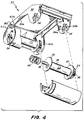
- the supply and take-up spools are shown in more detail in FIG. 4, which will be discussed later.
- the drive mechanisms 15 and 23 each include motors which respectively advance the carrier 14 and the receiver 12 in operative relation to the print head 18 as the various heating resistors 50 are selectively actuated to transfer dye.
- the carrier 14 is, as noted above, formed with a repeating series of thermally transferable dye frames. As shown in FIG. 3, each series includes yellow, magenta and cyan dye frames. A single series is, of course, used to print one colored image in the receiver 12. As we will see, the present invention corrects for a defective series which would be when at least one dye frame has an incorrect dye color density.
- the term "dye” refers to a colored material which transfers from the carrier to a receiver in response to energy applied by individual elements of the print head 18.
- the print head 18 is shown as having heat resistor elements, those skilled in the art will understand that other sources of energy, such as diode laser array and individual lasers, can be effectively used in accordance with this invention.
- the receiver After a colored image is formed in a receiver, the receiver will be referred to as a print.
- each dye frame extends across the width of the carrier 14.
- the carrier 14 comprises a leader portion followed by a repeating series of dye frames.
- the dye frames are contiguous and each series includes in sequence yellow, magenta, and cyan dye frames.
- LEDs 14a and 14b which illuminate the carrier from above.
- LED 14a emits yellow light
- LED 14b emits red light.
- Photodetectors A and B are disposed below the carrier and receive light which passes through the carrier.
- Photodetector A provides a signal to amplifier 17a
- photodetector B provides a signal to amplifier 17b.
- Threshold detectors 17c and 17d are connected to the output of amplifiers 17a and 17b, respectively.
- a logic 1 is provided by the threshold level detector to a ⁇ computer (microcomputer) 17. If it is below a threshold level, then a logic 0 is provided to the microcomputer 17.
- the microcomputer 17 in response to these signals identifies the start of series and each individual color dye frame in such series.
- U.S. Patent No. 4,710,781 to Stephenson the disclosure of which is incorporated by reference herein. It will be understood to those skilled in the art that other types of well known apparatus can be used to identify the start of each series of colored dye frames. See U.S. Patent No. 4,893,951.
- FIG. 4 is an exploded view of a cartridge 30 for carrier 14, the carrier being of a web-type.
- the cartridge 30 includes a body or housing 32 which may be of the type formed of an injection molded plastic.
- the body 32 includes two pairs of identical, spaced-apart flanges 32a and 32b.
- Each of the flanges includes detents 34.
- Each detent is adapted to rotatably capture a spindle 36 of its corresponding spool.
- the detent 34 is composed of two integral spring members 34a and 34b which deflect apart when the spindle 36 is inserted. After insertion, the spring members 34a and 34b return to their free position and the spindle 36 is free to rotate, but is spatially retained within its corresponding flange.
- non-volatile memory 60 mounteded on the cartridge 30 (preferably on body 32) is a non-volatile memory 60.
- This memory can be in the form of RAM with a permanent supply battery.
- One non-volatile memory that can be used is Dallas Semiconductor "Memory Button", part series 199x.
- the unit is a small battery-like can having two separable electrically conductive surfaces (60a and 60b).
- a two-point electrical communication format allows for the communication to the battery-backed memory element in the device.
- Two electrically separated contacts disposed within the printer provide a communication link between the printer and cartridge when the cartridge is inserted into the printer.
- Sets of other electrical components can be assembled into the cartridge to provide non-volatile data storage. Communication between the smart cartridge and printer can be accomplished using two or more wires or by the use of opto-electrical or radio frequency communication.
- Both the supply spool 20 and take-up spool 22 are identical in construction and so only one need be described.
- Each spool includes a cylindrical portion 38 about which the carrier 14 is wound.
- Guard members 39 and 40 are respectively secured to the opposite ends of the central portion 38. Their purpose is to align the spooled carrier 14 between them.
- the spindles 36 extend outwardly from their respective guide members 39 and 40 and terminate in a free end.
- a gear member 24 is fixed to a spindle 36 and disposed between guide member 40 and the free end of a spindle 36.
- the gear 24 tooth design is such that a portion extends out beyond the face of the gear in a direction parallel to the axis of spindle 36.
- a coil spring 48 urges each spool so that the face grooves of the gear 24 engage ribs 53 formed on flange 32b to prevent the spool from rotating when the cartridge is removed from the printer. This is especially advantageous during handling as it prevents the carrier 14 from unwinding.
- the non-volatile memory 60 is electrically connected to the microcomputer 17 as shown.
- the non-volatile memory 60 can be preprogrammed with information, including characteristics of the carrier or designated dye frames.
- the memory 60 can be preprogrammed with a counter that indicates the number of sets remaining to be used. It will also contain color-adjustment data which will be transferred into RAM memory of microcomputer 17 to change the color and contrast information to modify the output color image based upon variations in the color dye density of the colored dye frames of the receiver from desired levels.
- color signal processing which can be used in accordance with this invention, reference is made to commonly assigned U.S. Patent No. 4,786,917 to Hauschild et al, the disclosure of which is incorporated by reference herein.
- the drive mechanism 15 advances the carrier 14 until, in response to start of set signals provided by threshold detectors 17c and 17d, after the microcomputer 17 recognizes a start of series signal, it decrements the number of series remaining in the counter of memory 60.
- the carrier has been pre-examined and a defect location map is stored in the memory 60 which indicates the location or position of each series of frames in the carrier 14 containing a defective frame. If a series is defective, and the cartridge 30 is out of usable carrier (the number of sets remaining is "0"), the microcomputer 17 signals an indication on a display (not shown) that the cartridge 30 needs to be replaced.
- the microcomputer 17 causes the drive mechanism 23 to advance the carrier and the above process is repeated.
- the printer would print an image in a receiver 12 as discussed above.
- the color correction data is used by the print head control circuitry 42 to vary the actuation time of heating resistors 50 of the print head 18 as is well known in the art.
- the above process is repeated. If a non-defective carrier series does not remain, then the display will be caused to indicate that the cartridge is out of usable carrier.
- the carrier 14 When the cartridge 30 is removed from the printer to make, for example, special colored prints, after it is replaced the carrier 14 will be advanced until the first fresh (non-used) and non-defective series is presented under the print head 18. Every time a cartridge is replaced, the above discussed initialization process takes place.
- the present invention provides a supply having a spool with a carrier spirally wound on the spool.
- the carrier has a repeating series of dye frames of different dye colors.
- the carrier can be unwound from the spool.
- Electronically-operable memory means are mounted on the supply (preferably on the spool) for storing data corresponding to designated dye frames of the carrier, whereby upon connection of the cartridge to a thermal printer, the printer reads the data.
- thermal printer 10 includes a cover mechanism 80 having several major components attached to it. These components include a head positioning arm 81, a print head 18, supply spool 20, and take-up spool 22.
- a main printer support structure 92 includes a roller platen assembly 96, a transport mechanism 26, and a receiver supply 29. Thermal printer 10 is shown as it operates, with cover mechanism 80 in a closed position.
- the cover mechanism 80 is mounted to main printer support structure 92 through a cover mechanism mounting axis 93 which is coaxial with a cover mechanism mounting shaft 94. When a latch 95 is released, cover mechanism 80 can rotate to an open position.
- Head positioning arm 81 is mounted to cover mechanism 80 through a head positioning arm mounting axis 52 which is coaxial with a head positioning arm mounting shaft 51.
- Normal thermal printer operations include loading carrier, printing information upon a receiver and ejecting the finished print. Each of these operations is fully described in co-assigned U.S. Patent No. 5,176,458, which issued to H.G. Wirth on January 5, 1993. The disclosure of that patent is hereby incorporated into this specification by reference, and therefore only a brief description will be herein given of the illustrated embodiment of the thermal printer.
- Printer operation begins with the loading phase.
- the loading phase moves print head 18 to a loading position, advances receiver 12 to a printing location, and positions print head 18 in preparation for the printing operation.
- print head 18 and head positioning arm 81 begin in their ejecting positions, which are at the highest point of travel of head positioning arm 81 range of motion.
- a first cam 58 is driven to a loading position which is between the ejecting and the printing positions.
- a first cam follower 55 attached to head positioning arm 81 maintains contact with first cam 58, and head positioning arm 81 rotates about its mounting axis 52 to a loading position.
- a pin receiving recess 56 located on head positioning arm 81 constrains a first pin 72 of print head 18 to movement in one axis, which in the case of this embodiment is the vertical axis.
- first pin 72 contacts a side of pin receiving recess 56 and an adjustment screw, not shown, for setting the point at which head positioning arm 81 contacts first pin 72 as arm 81 moves from the print position to other positions, and for modifying the point in the head positioning arm's motion at which a second cam follower 76 contacts a second cam surface 77.
- Second cam follower 76 allows print head 18 to tilt toward roller platen assembly 96, until a guide 74 contacts platen assembly 96.
- print head 18 is spaced a distance away from platen assembly 96.
- Receiver 12 moves forward into a guide 28, where it follows a curved path toward a gap between print head 18 and platen assembly 96. As the receiver 12 moves into this gap, it contacts carrier 14 and is guided toward transport mechanism 26 and associated pinch roller 27. While this embodiment describes receiver 12 in sheet form, receiver 12 supplied in roll form could also be utilized.
- print head 18 moves toward platen assembly 96, pressing carrier 14 and receiver 12 against platen assembly 96 to form a sandwich for thermal printing.
- printer 10 When the loading phase of operation is completed, printer 10 enters the printing phase of operation, during which print head 18 presses carrier 14 and receiver 12 into platen assembly 96, and prints information on receiver 12.
- printer 10 enters the ejecting phase of operation, during which the print head 18 is retracted from the platen assembly 96 and the finished print is ejected from the printer.
- transport mechanism 26 which captures receiver 12 between it and pinch roller 27, drives the completed print out of thermal printer 10.
- the printer is ready to begin another printing operation.
- Figure 7 illustrates a roll 78 of thermal medium.
- the medium can be carrier as illustrated in Figures 2 and 3 or it could be receiver, even though the illustrated embodiment provides receiver in sheet form.
- Illustrated roll 78 can be a supply roll or a take-up roll.
- Roll 78 is spirally wound on a spool 70 having a longitudinal axis.
- the spool is a hollow cylindrical extrusion with open ends and an interior, but other constructions will readily occur to workers in the art.
- Spool 70 is preferably supported in a thermal printer by a pair of printer spindles received in the open ends of the spool.
- non-volatile memory device 60 mounteded on spool 70 is a non-volatile memory device 60.
- This memory device can be in the form of RAM with a permanent supply battery.
- One non-volatile memory device that can be used is Dallas Semiconductor "Memory Button", part series 199x, as discussed above.
- a two point electrical communication format allows for electrical communication to the battery-backed memory element in the canister.
- Two electrically separated contacts disposed within the printer provide a communication link between the printer and the memory element when roll 78 is inserted into the printer.
- Sets of other electrical components can be assembled into the spool to provide non-volatile data storage. Communication between the spool and printer can be accomplished using two or more wires or by the use of opto-electrical or radio frequency communication.
- memory device 60 is preferably mounted on a support 84 which has been slid into the hollow interior of spool 70 with a pressure fit.
- the memory device is preferably mounted along the longitudinal axis of spool 70.
- Other ways to mount the memory device to the carrier will readily occur to those skilled in the art.
- the non-volatile memory is electrically connected to a microcomputer, such as microcomputer 17.
- a microcomputer such as microcomputer 17.
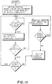
- the operation of the microcomputer for controlling the operation of the printer will now be explained with reference to the flowchart of Figure 10.
- Non-volatile memory 60 can be preprogrammed with information, including characteristics of the carrier or designated dye frames.
- the memory 50 can be preprogrammed with a counter that indicates the number of sets remaining to be used. It will also contain color-adjustment data which will be transferred into RAM memory of the printer microcomputer to change the color and contrast information to modify the output color image based upon variations in the color dye density of the colored dye frames of the dye receiver medium from desired levels.
- color signal processing which can be used in accordance with this invention, reference is made to commonly assigned U.S. Patent No. 4,786,917 to Hauschild et al, the disclosure of which is incorporated by reference herein. Other functions are also initialized, but they will not be discussed since they are not necessary to understand the invention.
- the printer microcomputer decrements the number of series remaining counter in memory 60 each time a start-of-series signal is provided by threshold detectors 17a and 17b of Figure 3.
- the carrier has been pre-examined, and a defect location map is stored in memory 60 which indicates the location or position of each series of frames in carrier 14 containing a defective frame. If a series is defective, and the roll 78 is out of usable carrier (the number of sets remaining is "zero"), the printer's microcomputer causes an operator alert to be displayed that the roll 78 needs to be replaced. If a set remains, then microcomputer causes the drive mechanism to advance the carrier and the above process is repeated. When a series is not defective, the printer would print an image in a receiver as discussed above.
- the color correction data is used by the print head control circuitry to vary the actuation time of resistors 50 of print head 18 as is well known in the art. After the print is made, if a series remains, the above process is repeated. If a non-defective series does not remain, then the display will be caused to indicate that the cartridge is out of usable dye donor medium.
- carrier 14 When carrier 14 is replaced in the printer after having been removed, such as to make special colored prints, the carrier will be advanced until the first fresh (non-used) and non-defective series is presented under the print head. Every time a roll is replaced, the above-discussed initialization process takes place.
Landscapes
- Engineering & Computer Science (AREA)
- General Engineering & Computer Science (AREA)
- Physics & Mathematics (AREA)
- General Physics & Mathematics (AREA)
- Theoretical Computer Science (AREA)
- Electronic Switches (AREA)
- Impression-Transfer Materials And Handling Thereof (AREA)
Applications Claiming Priority (4)
| Application Number | Priority Date | Filing Date | Title |
|---|---|---|---|
| US157767 | 1988-02-18 | ||
| US15776793A | 1993-11-24 | 1993-11-24 | |
| US08/241,977 US5455617A (en) | 1992-03-27 | 1994-05-12 | Thermal printer supply having non-volatile memory |
| US241977 | 1994-05-12 |
Publications (3)
| Publication Number | Publication Date |
|---|---|
| EP0654760A2 true EP0654760A2 (de) | 1995-05-24 |
| EP0654760A3 EP0654760A3 (de) | 1997-11-19 |
| EP0654760B1 EP0654760B1 (de) | 2000-04-19 |
Family
ID=26854474
Family Applications (1)
| Application Number | Title | Priority Date | Filing Date |
|---|---|---|---|
| EP94118348A Expired - Lifetime EP0654760B1 (de) | 1993-11-24 | 1994-11-22 | Thermodruckerzubehör mit nichtflüchtigem Speicher |
Country Status (4)
| Country | Link |
|---|---|
| US (1) | US5455617A (de) |
| EP (1) | EP0654760B1 (de) |
| JP (1) | JPH07214855A (de) |
| DE (1) | DE69424020T2 (de) |
Cited By (4)
| Publication number | Priority date | Publication date | Assignee | Title |
|---|---|---|---|---|
| WO2000059729A3 (en) * | 1999-04-08 | 2001-05-31 | Gerber Scient Products Inc | Wide format thermal printing apparatus including an ink donor sheet assembly with a memory |
| EP1053885A4 (de) * | 1998-12-03 | 2001-08-08 | Sony Corp | Thermotransferdruckersystem |
| US6802659B2 (en) | 1996-08-07 | 2004-10-12 | Mats Cremon | Arrangement for automatic setting of programmable devices and materials therefor |
| EP3064362A4 (de) * | 2013-10-31 | 2017-06-14 | Brother Kogyo Kabushiki Kaisha | Bandkassette und druckvorrichtung |
Families Citing this family (75)
| Publication number | Priority date | Publication date | Assignee | Title |
|---|---|---|---|---|
| GB9401055D0 (en) * | 1994-01-20 | 1994-03-16 | Ici Plc | Thermal transfer ribbon cassette |
| DE9407018U1 (de) * | 1994-04-27 | 1994-07-07 | Pelikan Produktions Ag, Egg | Farbbandkassette, insbesondere für einen Frankierautomaten |
| DE4427445C1 (de) * | 1994-08-03 | 1995-12-14 | Happich Gmbh Gebr | Lagervorrichtung, insbesondere für schwenkbar gelagerte Sonnenblenden von Fahrzeugen |
| US5748860A (en) * | 1995-06-06 | 1998-05-05 | R.R. Donnelley & Sons Company | Image processing during page description language interpretation |
| JPH1016340A (ja) * | 1996-07-02 | 1998-01-20 | Sony Corp | プリンタのインクリボンカートリッジ |
| USD423038S (en) * | 1996-12-30 | 2000-04-18 | Minolta Co., Ltd. | Ink reel |
| USD418860S (en) * | 1996-12-30 | 2000-01-11 | Minolta Co., Ltd. | Cartridge |
| US6685312B2 (en) | 1997-10-24 | 2004-02-03 | Fargo Electronics, Inc. | Ink jet card printer |
| US6702282B2 (en) | 1997-10-24 | 2004-03-09 | Fargo Electronics, Inc. | Card transport mechanism roller support |
| US6991388B2 (en) * | 1998-01-06 | 2006-01-31 | Brother Kogyo Kabushiki Kaisha | Ink ribbon cartridge having takeup-side cover with opening positioned beneath protrusion in cover |
| US20020186993A1 (en) | 1998-01-06 | 2002-12-12 | Brother Kogyo Kabushiki Kaisha | Ink ribbon cartridge |
| EP1000765A3 (de) * | 1998-01-06 | 2000-08-02 | Brother Kogyo Kabushiki Kaisha | Farbbandkassette |
| US6724895B1 (en) | 1998-06-18 | 2004-04-20 | Supersensor (Proprietary) Limited | Electronic identification system and method with source authenticity verification |
| US6071024A (en) * | 1998-06-26 | 2000-06-06 | Acer Peripherals, Inc. | Ink ribbon positioning system |
| US6099178A (en) | 1998-08-12 | 2000-08-08 | Eastman Kodak Company | Printer with media supply spool adapted to sense type of media, and method of assembling same |
| CA2277194A1 (en) * | 1998-08-12 | 2000-02-12 | Robert W. Spurr | A printer media supply spool adapted to allow the printer to sense type of media, and method of assembling same |
| EP1013455B1 (de) | 1998-12-22 | 2006-02-15 | Eastman Kodak Company | Drucker mit Transfer- und Empfangsmedienzuführkassetten, die alle einem Drucker erlauben, den Medientyp zu erfassen, und Verfahren zum Zusammenbau von Drucker und Kassetten |
| JP2000211222A (ja) * | 1999-01-21 | 2000-08-02 | Konica Corp | インクシ―ト、受像シ―ト、画像形成装置、画像形成方法、画像形成システム及び画像形成装置の集中制御システム |
| US6932527B2 (en) * | 1999-01-25 | 2005-08-23 | Fargo Electronics, Inc. | Card cartridge |
| ES2330915T3 (es) * | 1999-01-25 | 2009-12-17 | Fargo Electronics, Inc. | Metodo y aparato para la comunicacion entre una impresora o una plastificadora y sus suministros. |
| US7018117B2 (en) * | 1999-01-25 | 2006-03-28 | Fargo Electronics, Inc. | Identification card printer ribbon cartridge |
| US7344325B2 (en) | 1999-01-25 | 2008-03-18 | Fargo Electronics, Inc. | Identification card printer having ribbon cartridge with cleaner roller |
| US7154519B2 (en) * | 1999-01-25 | 2006-12-26 | Fargo Electronics, Inc. | Printer and ribbon cartridge |
| US6694884B2 (en) | 1999-01-25 | 2004-02-24 | Fargo Electronics, Inc. | Method and apparatus for communicating between printer and card supply |
| US6832866B2 (en) * | 1999-01-25 | 2004-12-21 | Fargo Electronics, Inc. | Printer or laminator supply |
| US6938976B2 (en) * | 1999-06-16 | 2005-09-06 | Eastman Kodak Company | Printer and method therefor adapted to sense data uniquely associated with a consumable loaded into the printer |
| US6644544B1 (en) | 1999-06-16 | 2003-11-11 | Eastman Kodak Company | Imaging apparatus capable of forming an image consistent with type of imaging consumable loaded therein and method of assembling the apparatus |
| US6266075B1 (en) * | 1999-07-08 | 2001-07-24 | Brady Worldwide, Inc. | Printer with memory device for storing platen pressures |
| US6363239B1 (en) | 1999-08-11 | 2002-03-26 | Eastman Kodak Company | Print having attached audio data storage and method of providing same |
| US6758616B2 (en) | 2000-01-21 | 2004-07-06 | Fargo Electronics, Inc. | Identification card printer |
| US6785739B1 (en) | 2000-02-23 | 2004-08-31 | Eastman Kodak Company | Data storage and retrieval playback apparatus for a still image receiver |
| ATE248067T1 (de) * | 2000-03-31 | 2003-09-15 | Brother Ind Ltd | Bildformungsgerät und in das bildformungsgerät montierte farbbandkassette |
| US6527356B1 (en) | 2000-06-02 | 2003-03-04 | Eastman Kodak Company | Printer capable of forming an image on a receiver substrate according to type of receiver substrate and a method of assembling the printer |
| JP2002029127A (ja) * | 2000-07-13 | 2002-01-29 | Mitsubishi Electric Corp | インクカセット、インクリボン供給容器及びインクリボンのインクカセットへの取り付け方法 |
| USD466150S1 (en) | 2000-09-29 | 2002-11-26 | Brother Industries, Ltd. | Tape cartridge for label printing machine |
| JP4582903B2 (ja) * | 2000-12-12 | 2010-11-17 | 三菱電機株式会社 | インクシートカートリッジおよびプリンタ |
| US6588872B2 (en) | 2001-04-06 | 2003-07-08 | Lexmark International, Inc. | Electronic skew adjustment in an ink jet printer |
| US7137000B2 (en) | 2001-08-24 | 2006-11-14 | Zih Corp. | Method and apparatus for article authentication |
| US20030061947A1 (en) * | 2001-10-01 | 2003-04-03 | Hohberger Clive P. | Method and apparatus for associating on demand certain selected media and value-adding elements |
| US6714228B1 (en) * | 2001-11-27 | 2004-03-30 | Nu-Kote International, Inc. | Ink ribbon cartridge with C-shaped sideplates |
| US6963351B2 (en) | 2001-12-21 | 2005-11-08 | Datacard Corporation | Radio frequency identification tags on consumable items used in printers and related equipment |
| US6570602B1 (en) * | 2002-02-06 | 2003-05-27 | Brady Worldwide, Inc. | Generating and storing supply specific printing parameters |
| US6985167B2 (en) | 2002-03-01 | 2006-01-10 | Fargo Electronics, Inc. | Card cleaner roller assembly |
| US20030197770A1 (en) | 2002-04-19 | 2003-10-23 | Klinefelter Gary M. | Card cartridge and card feed adapter for an ink jet sheet feeder printer |
| US20030197056A1 (en) * | 2002-04-19 | 2003-10-23 | Dunham Matthew K. | Identification card printer data encoder module |
| US6945524B2 (en) | 2002-09-05 | 2005-09-20 | Fargo Electronics, Inc. | Card singularization gate |
| US7233498B2 (en) | 2002-09-27 | 2007-06-19 | Eastman Kodak Company | Medium having data storage and communication capabilities and method for forming same |
| JP2004255701A (ja) * | 2003-02-26 | 2004-09-16 | Riso Kagaku Corp | 孔版原紙ロール |
| US7878505B2 (en) | 2003-08-19 | 2011-02-01 | Hid Global Corporation | Credential substrate rotator and processing module |
| US20050084315A1 (en) * | 2003-10-20 | 2005-04-21 | Zebra Technologies Corporation | Substrate cleaning apparatus and method |
| US7934881B2 (en) * | 2003-10-20 | 2011-05-03 | Zih Corp. | Replaceable ribbon supply and substrate cleaning apparatus |
| US7073963B2 (en) * | 2003-10-30 | 2006-07-11 | International Imaging Materials, Inc. | Film support devices and printing system handling ink film for printing |
| US7145464B2 (en) | 2003-11-19 | 2006-12-05 | Eastman Kodak Company | Data collection device |
| US7109986B2 (en) | 2003-11-19 | 2006-09-19 | Eastman Kodak Company | Illumination apparatus |
| US7009494B2 (en) | 2003-11-21 | 2006-03-07 | Eastman Kodak Company | Media holder having communication capabilities |
| US7206010B2 (en) * | 2004-04-16 | 2007-04-17 | Zih Corp. | Systems and methods for providing a media located on a spool and/or a cartridge where the media includes a wireless communication device attached thereto |
| US9296214B2 (en) | 2004-07-02 | 2016-03-29 | Zih Corp. | Thermal print head usage monitor and method for using the monitor |
| US8035482B2 (en) | 2004-09-07 | 2011-10-11 | Eastman Kodak Company | System for updating a content bearing medium |
| WO2006060541A2 (en) | 2004-11-30 | 2006-06-08 | Panduit Corp. | Market-based labeling system and method |
| US7245312B2 (en) * | 2005-06-10 | 2007-07-17 | Zih Corp. | Thermal printer with quick-release printhead assembly |
| TWI289111B (en) * | 2005-08-01 | 2007-11-01 | Hi Touch Imaging Tech Co Ltd | Ribbon transportation device capable of fastening ribbon |
| US8721203B2 (en) | 2005-10-06 | 2014-05-13 | Zih Corp. | Memory system and method for consumables of a printer |
| US7802933B2 (en) * | 2005-12-23 | 2010-09-28 | Eastman Kodak Company | Thermal printer cartridge with energy absorbing features |
| ATE434529T1 (de) | 2006-06-30 | 2009-07-15 | Ici Ltd | Thermisches farbstoffübertragungsblatt und drucker |
| US20080180477A1 (en) * | 2007-01-31 | 2008-07-31 | Trombley Donald C | Identification of characteristics of media used in a printer apparatus |
| EP2285581A1 (de) * | 2008-06-13 | 2011-02-23 | Brady Worldwide, Inc. | System und verfahren zur überwachung und bestimmung der menge eines bandes auf einer in einem drucker verwendeten zufuhrspule |
| JP2010036399A (ja) * | 2008-08-01 | 2010-02-18 | Dainippon Printing Co Ltd | ボビン |
| ES2547136T3 (es) | 2009-09-18 | 2015-10-02 | Assa Abloy Ab | Rotador de sustrato de tarjeta |
| DE102009053093A1 (de) * | 2009-11-13 | 2011-05-19 | Mühlbauer Ag | Verfahren und Vorrichtung zum Ermitteln einer Farbe |
| WO2013025749A1 (en) | 2011-08-15 | 2013-02-21 | Videojet Technologies Inc. | Thermal transfer printer |
| TW201318881A (zh) * | 2011-11-15 | 2013-05-16 | Hiti Digital Inc | 可辨別色帶形式之列印系統 |
| JP1467232S (de) * | 2012-09-14 | 2016-04-11 | ||
| GB2512618A (en) * | 2013-04-03 | 2014-10-08 | Markem Imaje Ltd | Tape drive and method of operating a tape drive |
| US12533897B2 (en) | 2024-03-12 | 2026-01-27 | Brady Worldwide, Inc. | Printer material holder system and method |
| US12697829B2 (en) | 2024-07-31 | 2026-08-04 | Brady Worldwide, Inc. | Printhead force adjust and lift system and method |
Family Cites Families (16)
| Publication number | Priority date | Publication date | Assignee | Title |
|---|---|---|---|---|
| JPS6021279A (ja) * | 1983-07-15 | 1985-02-02 | Toshiba Corp | 画像形成装置 |
| US4710781A (en) * | 1986-08-04 | 1987-12-01 | Eastman Kodak Company | Thermal printer color dye frame identification using red and yellow light sources |
| US4723133A (en) * | 1987-02-12 | 1988-02-02 | Eastman Kodak Company | Card ejecting apparatus |
| JP2576492B2 (ja) * | 1987-03-20 | 1997-01-29 | ソニー株式会社 | プリンタ装置のリボン送り機構 |
| DE3718013C1 (de) * | 1987-05-27 | 1988-11-10 | Triumph Adler Ag | Farbbandkassette fuer elektronisch gesteuerte Schreib- oder aehnliche Bueromaschinen |
| US4786917A (en) * | 1987-06-03 | 1988-11-22 | Eastman Kodak Company | Signal processing for a thermal printer |
| JPH01310987A (ja) * | 1988-06-08 | 1989-12-15 | Canon Inc | 記録装置 |
| EP0433280B1 (de) * | 1988-07-25 | 1993-04-28 | Siemens Aktiengesellschaft | Anordnung für druckeinrichtungen zur überwachung von druckmedium enthaltenden vorratsbehältern |
| JP2749075B2 (ja) * | 1988-10-03 | 1998-05-13 | 株式会社日立製作所 | 熱転写記録装置及びインク紙カセット |
| US5278577A (en) * | 1989-07-18 | 1994-01-11 | Dai Nippon Insatsu Kabushiki Kaisha | Method of carrying out a thermal transfer printing by using a thermal transfer printer |
| US5035325A (en) * | 1989-07-18 | 1991-07-30 | Dai Nippon Insatsu Kabushiki Kaisha | Cassette for thermal transfer printing film |
| JP3222454B2 (ja) * | 1990-02-02 | 2001-10-29 | キヤノン株式会社 | インクタンクカートリッジ |
| JP3002001B2 (ja) * | 1991-03-20 | 2000-01-24 | 日本碍子株式会社 | ナトリウム−硫黄電池における火災の消火装置 |
| US5266968A (en) * | 1992-03-27 | 1993-11-30 | Eastman Kodak Company | Non-volatile memory thermal printer cartridge |
| US5176458A (en) * | 1992-06-08 | 1993-01-05 | Eastman Kodak Company | Multiple position thermal printer head mechanism which is disturbance insensitive |
| US5318370A (en) * | 1992-11-17 | 1994-06-07 | Varitronic Systems, Inc. | Cartridge with data memory system and method regarding same |
-
1994
- 1994-05-12 US US08/241,977 patent/US5455617A/en not_active Expired - Lifetime
- 1994-11-21 JP JP6286946A patent/JPH07214855A/ja active Pending
- 1994-11-22 DE DE69424020T patent/DE69424020T2/de not_active Expired - Lifetime
- 1994-11-22 EP EP94118348A patent/EP0654760B1/de not_active Expired - Lifetime
Cited By (9)
| Publication number | Priority date | Publication date | Assignee | Title |
|---|---|---|---|---|
| US6802659B2 (en) | 1996-08-07 | 2004-10-12 | Mats Cremon | Arrangement for automatic setting of programmable devices and materials therefor |
| EP1053885A4 (de) * | 1998-12-03 | 2001-08-08 | Sony Corp | Thermotransferdruckersystem |
| US6494628B1 (en) | 1998-12-03 | 2002-12-17 | Sony Corporation | Heat-sensitive transcription printer system |
| KR100806236B1 (ko) * | 1998-12-03 | 2008-02-22 | 소니 가부시끼 가이샤 | 감열전사 프린터 시스템 |
| WO2000059729A3 (en) * | 1999-04-08 | 2001-05-31 | Gerber Scient Products Inc | Wide format thermal printing apparatus including an ink donor sheet assembly with a memory |
| US6243120B1 (en) | 1999-04-08 | 2001-06-05 | Gerber Scientific Products, Inc. | Replaceable donor sheet assembly with memory for use with a thermal printer |
| US6603497B2 (en) | 1999-04-08 | 2003-08-05 | Gerber Scientific Products, Inc. | Replaceable donor sheet assembly with memory for use with a thermal printer |
| EP3064362A4 (de) * | 2013-10-31 | 2017-06-14 | Brother Kogyo Kabushiki Kaisha | Bandkassette und druckvorrichtung |
| US9789712B2 (en) | 2013-10-31 | 2017-10-17 | Brother Kogyo Kabushiki Kaisha | Tape cartridge and printer |
Also Published As
| Publication number | Publication date |
|---|---|
| JPH07214855A (ja) | 1995-08-15 |
| DE69424020D1 (de) | 2000-05-25 |
| DE69424020T2 (de) | 2000-11-16 |
| EP0654760B1 (de) | 2000-04-19 |
| US5455617A (en) | 1995-10-03 |
| EP0654760A3 (de) | 1997-11-19 |
Similar Documents
| Publication | Publication Date | Title |
|---|---|---|
| EP0654760B1 (de) | Thermodruckerzubehör mit nichtflüchtigem Speicher | |
| EP0562979B1 (de) | Kassette mit einem nichtlöschbaren Speicher für Thermo-Drucker | |
| EP0327076B1 (de) | Bandzuführvorrichtung für Thermo-Drucker | |
| US5743663A (en) | Record medium feeding in a color thermal printer | |
| US4702631A (en) | Thermal ribbon cassette and housing therefore | |
| US4616236A (en) | Image forming apparatus with color transfer material | |
| EP0327073B1 (de) | Thermo-Drucker und seine Bandkassette | |
| US4660053A (en) | Thermal transfer recording apparatus | |
| US4718785A (en) | Compliant head loading mechanism for thermal printer | |
| EP0473132B1 (de) | Wärmedrucker mit einer Wegwerfkassette | |
| US5249873A (en) | Method and apparatus for thermal transfer recording and ink paper cassette therefor | |
| US4611218A (en) | Thermal head positioning apparatus with ribbon cassette | |
| US6082913A (en) | Cartridge for printing | |
| JP4130520B2 (ja) | ドナーと受像媒体の供給トレイを有するプリンタ、及びプリンタとトレイを組み立てる方法 | |
| EP0628417B1 (de) | Vorrichtung zum Drucken von Videobildern | |
| US4669899A (en) | Ink ribbon cartridge and color ink ribbon for printer | |
| KR100210461B1 (ko) | 프린터 | |
| EP0301076B1 (de) | Kartenauswerfvorrichtung | |
| US6219077B1 (en) | Printer system | |
| DE69110310T2 (de) | Thermotransfer-Aufzeichnungsapparat und Faksimileapparat mit Verwendung des ersteren. | |
| EP0440236B1 (de) | Thermotransfer-Aufzeichnungsapparat und Faksimileapparat mit Verwendung des ersteren | |
| US5248996A (en) | Thermal transfer recording apparatus which avoids ink sheet sticking after recording data reception is interrupted | |
| JPH1178190A (ja) | 記録装置 | |
| EP0679525A2 (de) | Bandkassetten-Antriebssystem in tragbaren Kopierern und Druckern | |
| JPH0632977B2 (ja) | インクリボンプリンタ |
Legal Events
| Date | Code | Title | Description |
|---|---|---|---|
| PUAI | Public reference made under article 153(3) epc to a published international application that has entered the european phase |
Free format text: ORIGINAL CODE: 0009012 |
|
| AK | Designated contracting states |
Kind code of ref document: A2 Designated state(s): DE FR GB |
|
| PUAL | Search report despatched |
Free format text: ORIGINAL CODE: 0009013 |
|
| AK | Designated contracting states |
Kind code of ref document: A3 Designated state(s): DE FR GB |
|
| 17P | Request for examination filed |
Effective date: 19980429 |
|
| 17Q | First examination report despatched |
Effective date: 19990308 |
|
| GRAG | Despatch of communication of intention to grant |
Free format text: ORIGINAL CODE: EPIDOS AGRA |
|
| GRAG | Despatch of communication of intention to grant |
Free format text: ORIGINAL CODE: EPIDOS AGRA |
|
| GRAH | Despatch of communication of intention to grant a patent |
Free format text: ORIGINAL CODE: EPIDOS IGRA |
|
| GRAH | Despatch of communication of intention to grant a patent |
Free format text: ORIGINAL CODE: EPIDOS IGRA |
|
| GRAA | (expected) grant |
Free format text: ORIGINAL CODE: 0009210 |
|
| AK | Designated contracting states |
Kind code of ref document: B1 Designated state(s): DE FR GB |
|
| REF | Corresponds to: |
Ref document number: 69424020 Country of ref document: DE Date of ref document: 20000525 |
|
| ET | Fr: translation filed | ||
| PLBE | No opposition filed within time limit |
Free format text: ORIGINAL CODE: 0009261 |
|
| STAA | Information on the status of an ep patent application or granted ep patent |
Free format text: STATUS: NO OPPOSITION FILED WITHIN TIME LIMIT |
|
| 26N | No opposition filed | ||
| REG | Reference to a national code |
Ref country code: GB Ref legal event code: IF02 |
|
| PGFP | Annual fee paid to national office [announced via postgrant information from national office to epo] |
Ref country code: DE Payment date: 20111130 Year of fee payment: 18 |
|
| PGFP | Annual fee paid to national office [announced via postgrant information from national office to epo] |
Ref country code: FR Payment date: 20121113 Year of fee payment: 19 |
|
| PGFP | Annual fee paid to national office [announced via postgrant information from national office to epo] |
Ref country code: GB Payment date: 20121025 Year of fee payment: 19 |
|
| REG | Reference to a national code |
Ref country code: DE Ref legal event code: R119 Ref document number: 69424020 Country of ref document: DE Effective date: 20130601 |
|
| PG25 | Lapsed in a contracting state [announced via postgrant information from national office to epo] |
Ref country code: DE Free format text: LAPSE BECAUSE OF NON-PAYMENT OF DUE FEES Effective date: 20130601 |
|
| GBPC | Gb: european patent ceased through non-payment of renewal fee |
Effective date: 20131122 |
|
| REG | Reference to a national code |
Ref country code: FR Ref legal event code: ST Effective date: 20140731 |
|
| PG25 | Lapsed in a contracting state [announced via postgrant information from national office to epo] |
Ref country code: GB Free format text: LAPSE BECAUSE OF NON-PAYMENT OF DUE FEES Effective date: 20131122 Ref country code: FR Free format text: LAPSE BECAUSE OF NON-PAYMENT OF DUE FEES Effective date: 20131202 |