EP0655331A1 - Dispositif pour contrôler le positionnement en registre de plaques sur le cylindre porte-plaque de machines à imprimer - Google Patents
Dispositif pour contrôler le positionnement en registre de plaques sur le cylindre porte-plaque de machines à imprimer Download PDFInfo
- Publication number
- EP0655331A1 EP0655331A1 EP94117300A EP94117300A EP0655331A1 EP 0655331 A1 EP0655331 A1 EP 0655331A1 EP 94117300 A EP94117300 A EP 94117300A EP 94117300 A EP94117300 A EP 94117300A EP 0655331 A1 EP0655331 A1 EP 0655331A1
- Authority
- EP
- European Patent Office
- Prior art keywords
- plate cylinder
- stop
- printing
- stops
- coil
- Prior art date
- Legal status (The legal status is an assumption and is not a legal conclusion. Google has not performed a legal analysis and makes no representation as to the accuracy of the status listed.)
- Granted
Links
- 238000007639 printing Methods 0.000 title claims abstract description 27
- 239000003990 capacitor Substances 0.000 claims description 12
- 238000004080 punching Methods 0.000 claims description 4
- 239000000463 material Substances 0.000 claims description 2
- 238000007645 offset printing Methods 0.000 claims 1
- 230000003534 oscillatory effect Effects 0.000 abstract 2
- 238000012544 monitoring process Methods 0.000 abstract 1
- 238000011156 evaluation Methods 0.000 description 5
- 102000001999 Transcription Factor Pit-1 Human genes 0.000 description 2
- 108010040742 Transcription Factor Pit-1 Proteins 0.000 description 2
- 230000008878 coupling Effects 0.000 description 2
- 238000010168 coupling process Methods 0.000 description 2
- 238000005859 coupling reaction Methods 0.000 description 2
- 239000000919 ceramic Substances 0.000 description 1
- 230000002950 deficient Effects 0.000 description 1
- 238000011161 development Methods 0.000 description 1
- 230000018109 developmental process Effects 0.000 description 1
- 239000000428 dust Substances 0.000 description 1
- 239000002184 metal Substances 0.000 description 1
- 239000003973 paint Substances 0.000 description 1
- 230000008054 signal transmission Effects 0.000 description 1
- 238000005476 soldering Methods 0.000 description 1
Images

Classifications
-
- B—PERFORMING OPERATIONS; TRANSPORTING
- B41—PRINTING; LINING MACHINES; TYPEWRITERS; STAMPS
- B41F—PRINTING MACHINES OR PRESSES
- B41F27/00—Devices for attaching printing elements or formes to supports
- B41F27/12—Devices for attaching printing elements or formes to supports for attaching flexible printing formes
- B41F27/1206—Feeding to or removing from the forme cylinder
-
- B—PERFORMING OPERATIONS; TRANSPORTING
- B41—PRINTING; LINING MACHINES; TYPEWRITERS; STAMPS
- B41F—PRINTING MACHINES OR PRESSES
- B41F27/00—Devices for attaching printing elements or formes to supports
- B41F27/005—Attaching and registering printing formes to supports
-
- B—PERFORMING OPERATIONS; TRANSPORTING
- B41—PRINTING; LINING MACHINES; TYPEWRITERS; STAMPS
- B41P—INDEXING SCHEME RELATING TO PRINTING, LINING MACHINES, TYPEWRITERS, AND TO STAMPS
- B41P2227/00—Mounting or handling printing plates; Forming printing surfaces in situ
- B41P2227/30—Detecting the correct position of printing plates on the cylinder
Definitions
- the invention relates to a device for checking the registration of printing plates on the plate cylinder of printing machines according to the preamble of claim 1.
- the printing plates for the differently colored partial images are mounted on a plate cylinder.
- Each printing plate is fastened (clamped) with an edge assigned to the start of printing in a clamping rail and then placed around the outer circumference of the cylinder until the rear edge associated with the printing end can in turn be fastened in a clamping rail.
- the pressure plate is then tensioned.
- the disadvantage here is that the dowel pins, which are designed as switches, are electrically connected in series, so that an incorrect system on one side already leads to an interruption of the circuit. It cannot be determined on which side there is an incorrect system.
- Another disadvantage is that the plate cylinder has contact surfaces that can be contaminated by dampening solution, paint, paper dust, so that a perfect signal transmission is no longer possible.
- EP 0 555 782 A1 Also known from EP 0 555 782 A1 are locating pins, which are electrically insulated from the potential of the plate cylinder in the area of the clamping rail assigned to the start of pressure.
- a resonant circuit referred to in this document as a resonator, which is closed electrically by the correct contact of the pressure plate with its U-shaped punched-out holes on the electrically insulated dowel pins.
- a secondary coil is attached, which can be assigned a primary coil suspended on the frame, so that the alternating magnetic field generated by the primary coil can penetrate the secondary coil at a certain position of the plate cylinder.
- the primary coil is driven by an electrically powered oscillator and evaluation electronics, so that when the pressure plate is correctly seated on the dowel pins (resonant circuit on the plate cylinder closed), there is a large coupling between the two coils and thus the oscillator via the primary coil high performance is withdrawn.
- This power loss can be detected by a circuit and serves as an indication of the registration of the pressure plate on the dowel pins.
- the basic principle of this device is also known from GB-PS 1 321 562.
- EP 0 551 976 A1 and EP 0 555 782 A1 A disadvantage of the objects of EP 0 551 976 A1 and EP 0 555 782 A1 is that the electrically interrogable dowel pins are electrically connected in series. In order to do this, it is also necessary to lay lines, wires or the like in the plate cylinder. This is not only time-consuming with regard to assembly, it is also prone to failure due to cable breaks or defective soldering.
- the object of the present invention is therefore to develop a device according to the preamble of claim 1 in such a way that a safe and more accurate determination of a register-correct system at the stops attached in the plate cylinder is possible.
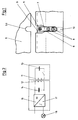
- FIG. 1 shows a part of the plate cylinder 1 assigned to the pressure start DA with a pit 2 and the clamping rail 3 assigned to the pressure start DA.
- the clamping rail 3 consists, for example, of an upper clamping rail 3.1 fixedly mounted on the bottom of the pit 2 and a lower clamping rail movably arranged relative thereto 3.2.
- a pressure plate for fastening to the clamping rail 3 is inserted into the receiving gap 4 between the respective surfaces of the lower clamping rail 3.2 and the upper clamping rail 3.1. Then the lower clamping rail 3.2 is pressed under force against the upper clamping rail 3.1.
- FIG. 1 shows a top view of the clamping rail 3 or the upper clamping rail 3.1 according to FIG. 1.
- the edge area of a printing plate 5 associated with the start of printing DA (FIG. 2) is shown.
- the pressure plate 5 has two punched-outs 5.1 with a U-shaped shape in its front edge, one of which is shown in FIG. 1 and also only one stop 7 cooperating with this punched-out 5.1.
- a groove-shaped recess 6 is milled into the upper clamping rail 3.1 for each stop 7 provided.
- the recess 6 is additionally widened in the part of the upper clamping rail 3.1 which projects beyond the lower clamping rail 3.2.
- the bottom of this groove-shaped recess 6 is lower than the upper surface of the lower clamping rail 3.2 when the lower clamping rail 3.2 is maximally lowered or when the receiving gap 4 is fully open.
- a stop 7 in the form of a plate or a tongue is inserted into the groove-shaped recess 6 of the upper clamping rail 3.1.
- the end of the stop 7 facing the front edge of the pressure plate 5 is adapted in accordance with the provided register systems of the punchings 5.1 in the pressure plate 5.
- the stop 7 is fastened to the upper clamping rail 3.1 via two fastening screws 8 in the respective recess 6. Furthermore, adjusting screws 10 (grub screw) are also provided, by means of which the stop 7 can be adjusted in the circumferential direction of the plate cylinder 1.
- the lower clamping rail 3.2 Since the underside of the stops 7 rests on the bottom of the recess 6 and, as provided, this lies somewhat lower than the upper side of the lower clamping rail 3.2 in the fully open position, the lower clamping rail 3.2 has a groove 9 in the region of the stops 7, which allows the receiving gap 4 to be closed.
- a secondary coil 11 in the form of a ring coil is attached in the stop 7, the front end of which is shown in the radial direction out of the plate cylinder 1 (FIG. 1).
- Fig. 2 it is shown in principle that each stop 7 - it should be mentioned again that the clamping rail 4 of the pressure start DA two axially spaced stops 7 of the type described here are assigned - a primary coil 12 attached to an adjusting device 15th is assigned, which can be brought as close as possible to the secondary coil 11 when the plate cylinder 1 is in a position.
- the adjusting device 15 is, for example, in each case a lever which is pivotally mounted on the frame side about a horizontal axis and has the primary coil 12 at its pivotable end is appropriate. Provision can also be made for the adjusting device 15, which is arranged at each stop 7, to be pivotably arranged on the protection (not shown here) which is mounted vertically in front of the printing unit cylinders, or can be arranged in some other way.
- stop means can be provided, by means of which the adjusting device 15 and thus the primary coil 12 can be brought into a defined distance from the secondary coil 11.
- the stops can be supported either directly on the top of the stops 7 or on the outer surface of the upper clamping rail 3.1.
- the pivoting of the adjusting device 15 assigned to each stop 7 is carried out by a pneumatic cylinder or the like, not shown.
- the adjusting device 15 is shown in the so-called query position, i.e. the primary coil 12 is as close as possible to the secondary coil 11. In the printing mode, the adjusting device 15 is turned off by the plate cylinder 1 by pivoting it away.
- Fig. 2 it is indicated that the ends of the primary coil 12 are connected to an oscillator and evaluation electronics 16, 17.
- the basic principle of the circuit according to FIG. 3 is known per se and is therefore only briefly explained here.
- a secondary coil 11 and a series of capacitors 13 are connected in the stop 7.
- the switch arranged here in this secondary-side resonant circuit corresponds to the electrically insulated attachment of the stops with respect to the plate cylinder 1 and is closed by correctly pressing the pressure plate with its U-shaped cutouts 5.1 against the stops 7.
- the adjusting device 15 with the primary coil 12 is placed against the secondary coil 11 of a stop 7, the coupling indicated in the circuit according to FIG. 3 results Secondary coil 11 and the primary coil 12.
- a capacitor 14 is connected in parallel with the primary coil 12, so that the same natural frequency results as the secondary-side resonant circuit consisting of the secondary coil 11 with the capacitor 13. If the primary coil 12 now turns on via the adjusting device 15 the secondary coil 11 is turned on, the oscillator 16 is switched on to feed the primary-side resonant circuit. If the pressure plate 5 with its U-shaped punched-outs 5.1 lies correctly against the stop 7, the switch according to FIG. 3 is closed.
- evaluation electronics 17 which is known per se, is connected to the oscillator 16, by means of which the drop in performance can be determined and, as indicated, indicated.
- the stops 7 consist, for example, of ceramic or plastic material, which was cast in a corresponding shape around the secondary coil 11 and the capacitor 13 with the corresponding electrical connecting means.
- two contact surfaces 19 made of metal are attached to the side of the stop 7 facing the U-shaped punch 5.1.
- the two contact surfaces 19 are electrically insulated from one another in the middle plane of the stop 7 and are therefore only short-circuited to one another if the U-shaped stamping 5.1 of the pressure plate 5 lies cleanly on this outer contour with the contact surfaces 19.
- the contact surfaces 19 are connected to one end of the secondary coil 11 and to the one side of the capacitor 13. The corresponding other poles of secondary coil 11 and capacitor 13 are connected directly to one another.
- FIG. 5 shows a further variant of the design of the stops 7 according to the invention.
- the stop 7 is shown in section as in FIG. 2.
- a contact surface 20 is attached, which is directly electrically connected to the one pole of the secondary coil 11.
- a second contact surface 21 is attached over a large area. This contact surface is connected to one pole of the capacitor 13. Again, the corresponding remaining poles of the secondary coil 11 and capacitor 13 are connected to one another.
- the switch symbolically represented in FIG. 3 is closed when the pressure plate 5 with its U-shaped punching 5.1 is correctly seated on the end face of the stop 7, ie the contact surface 20.
- the outer jacket of the plate cylinder 1 By contact with the outer jacket of the plate cylinder 1, it is in electrical contact with it, so that in the electrically conductive connection via the contact surface 21 the secondary-side resonant circuit, consisting of the secondary coil 11 and capacitor 13, is closed.
Landscapes
- Inking, Control Or Cleaning Of Printing Machines (AREA)
- Supply, Installation And Extraction Of Printed Sheets Or Plates (AREA)
Applications Claiming Priority (2)
| Application Number | Priority Date | Filing Date | Title |
|---|---|---|---|
| DE4340052 | 1993-11-24 | ||
| DE4340052A DE4340052C2 (de) | 1993-11-24 | 1993-11-24 | Vorrichtung zur Kontrolle der registergerechten Anlage einer Druckplatte auf einem Plattenzylinder einer Druckmaschine |
Publications (2)
| Publication Number | Publication Date |
|---|---|
| EP0655331A1 true EP0655331A1 (fr) | 1995-05-31 |
| EP0655331B1 EP0655331B1 (fr) | 1997-01-02 |
Family
ID=6503340
Family Applications (1)
| Application Number | Title | Priority Date | Filing Date |
|---|---|---|---|
| EP94117300A Expired - Lifetime EP0655331B1 (fr) | 1993-11-24 | 1994-11-03 | Dispositif pour contrÔler le positionnement en registre de plaques sur le cylindre porte-plaque de machines à imprimer |
Country Status (3)
| Country | Link |
|---|---|
| EP (1) | EP0655331B1 (fr) |
| AT (1) | ATE147012T1 (fr) |
| DE (2) | DE4340052C2 (fr) |
Cited By (2)
| Publication number | Priority date | Publication date | Assignee | Title |
|---|---|---|---|---|
| EP0982129A1 (fr) * | 1998-08-28 | 2000-03-01 | MAN Roland Druckmaschinen AG | Dispositif de commande de registre |
| EP1357071A3 (fr) * | 2002-03-27 | 2005-04-13 | Fuji Photo Film Co., Ltd. | Dispositif pour le positionnement de matériaux en feuille |
Families Citing this family (6)
| Publication number | Priority date | Publication date | Assignee | Title |
|---|---|---|---|---|
| DE19607297C2 (de) * | 1996-02-27 | 1999-09-02 | Koenig & Bauer Ag | Kontrolleinrichtung für Druckplatten |
| DE19754003C2 (de) * | 1997-12-05 | 2002-09-19 | Koenig & Bauer Ag | Vorrichtung zur Kontrolle der registergerechten Lage einer Druckplatte |
| DE19803727A1 (de) * | 1998-01-30 | 1999-08-05 | Heidelberger Druckmasch Ag | Verfahren und Vorrichtung zum automatischen Zuführen und/oder Entfernen von Druckplatten zum/vom Plattenzylinder einer Druckmaschine |
| DE102005061912A1 (de) * | 2005-12-23 | 2007-07-05 | Koenig & Bauer Aktiengesellschaft | Vorrichtung und Verfahren zur Detektion der Lage einer Druckplatte in einer Druckmaschine |
| DE102007039824B4 (de) * | 2007-08-23 | 2009-05-20 | Manroland Ag | Registerstegeinrichtung für eine Bogendruckmaschine |
| DE102010028686A1 (de) | 2010-05-06 | 2011-11-10 | Manroland Ag | Formzylinder einer Druckmaschine |
Citations (2)
| Publication number | Priority date | Publication date | Assignee | Title |
|---|---|---|---|---|
| EP0551976A1 (fr) * | 1992-01-17 | 1993-07-21 | Komori Corporation | Dispositif pour monter une plaque sur un cylindre porte-plaque |
| EP0555782A1 (fr) * | 1992-02-10 | 1993-08-18 | Komori Corporation | Dispositif pour confirmer la condition d'insertion d'une plaque d'impression |
Family Cites Families (2)
| Publication number | Priority date | Publication date | Assignee | Title |
|---|---|---|---|---|
| DE3940796A1 (de) * | 1989-12-09 | 1991-06-13 | Koenig & Bauer Ag | Verfahren und einrichtung zum automatischen wechseln einer druckplatte |
| DE9215069U1 (de) * | 1992-11-05 | 1992-12-17 | MAN Roland Druckmaschinen AG, 6050 Offenbach | Vorrichtung für das registergerechte Anlegen von Druckplatten auf dem Plattenzylinder von Druckmaschinen |
-
1993
- 1993-11-24 DE DE4340052A patent/DE4340052C2/de not_active Expired - Fee Related
-
1994
- 1994-11-03 DE DE59401467T patent/DE59401467D1/de not_active Expired - Fee Related
- 1994-11-03 AT AT94117300T patent/ATE147012T1/de not_active IP Right Cessation
- 1994-11-03 EP EP94117300A patent/EP0655331B1/fr not_active Expired - Lifetime
Patent Citations (2)
| Publication number | Priority date | Publication date | Assignee | Title |
|---|---|---|---|---|
| EP0551976A1 (fr) * | 1992-01-17 | 1993-07-21 | Komori Corporation | Dispositif pour monter une plaque sur un cylindre porte-plaque |
| EP0555782A1 (fr) * | 1992-02-10 | 1993-08-18 | Komori Corporation | Dispositif pour confirmer la condition d'insertion d'une plaque d'impression |
Cited By (2)
| Publication number | Priority date | Publication date | Assignee | Title |
|---|---|---|---|---|
| EP0982129A1 (fr) * | 1998-08-28 | 2000-03-01 | MAN Roland Druckmaschinen AG | Dispositif de commande de registre |
| EP1357071A3 (fr) * | 2002-03-27 | 2005-04-13 | Fuji Photo Film Co., Ltd. | Dispositif pour le positionnement de matériaux en feuille |
Also Published As
| Publication number | Publication date |
|---|---|
| ATE147012T1 (de) | 1997-01-15 |
| EP0655331B1 (fr) | 1997-01-02 |
| DE4340052A1 (de) | 1995-06-08 |
| DE4340052C2 (de) | 1996-06-13 |
| DE59401467D1 (de) | 1997-02-13 |
Similar Documents
| Publication | Publication Date | Title |
|---|---|---|
| DE69303380T3 (de) | Vorrichtung zum Anbringen einer Platte auf einem Plattenzylinder | |
| EP0582903B1 (fr) | Dispositif de contrÔle du positionnement repéré d'une plaque d'impression sur un cylindre de plaque d'une machine à imprimer, en particulier d'une machine offset d'impression de feuilles | |
| EP0579017B1 (fr) | Dispositif pour tendre une plaque d'impression sur un cylindre de plaque | |
| EP0075900B1 (fr) | Dispositif de contrôle du repérage exact dans un mécanisme de tension de plaques d'impression sur le cylindre de plaque d'une machine d'impression offset | |
| EP0596337B2 (fr) | Dispositif pour placer en répérage des plaques d'impression sur des cylindres de plaque des machines | |
| EP0711664B1 (fr) | Dispositif pour placer en repérage des plaques d'impression | |
| DE4439623C2 (de) | Verfahren zum automatischen Zuführen von Druckplatten | |
| EP0655331B1 (fr) | Dispositif pour contrÔler le positionnement en registre de plaques sur le cylindre porte-plaque de machines à imprimer | |
| EP1155837A2 (fr) | Machine à imprimer avec un cylindre porte-plaque portant plusieurs plaques | |
| DE2852521A1 (de) | Befestigungsanordnung fuer ein auf einer walze aufzuspannendes matrizenblatt | |
| EP1738905B1 (fr) | Cylindre d'une machine d'impression rotative avec un canal parallèle à l'axe du cylindre | |
| EP0727311A1 (fr) | Dispositif pour échanger des plaques d'impression | |
| EP1046503B1 (fr) | Dispositif pour contrôler la position des plaques d'impression | |
| DD290627A5 (de) | Vorrichtung zum befestigen einer biegsamen druckplatte | |
| EP0982130B1 (fr) | Dispositif de commande de registre | |
| DE19746456A1 (de) | Digitales Drucksystem mit einer Vorrichtung zur Bearbeitung einer Materialbahn | |
| EP0635367B1 (fr) | Dispositif de positionnement de clichés sur le cylindre porte-plaque d'une machine d'impression | |
| EP0619185A1 (fr) | Dispositif pour fabriquer un manchon, en particulier une plaque d'impression en forme de manchon à surface continue | |
| EP1046502B1 (fr) | Dispositif de contrôle du positionnement repéré des plaques d'impression | |
| DE19539453A1 (de) | Paßsystem zum Ausrichten von Druckplatten für Offset-Druckmaschinen | |
| DE3144643C2 (de) | Vorrichtung zur Anzeige einer axialen Verschiebung von Spannschienen für das Aufspannen von Druckplatten auf dem Plattenzylinder von Druckmaschinen | |
| DE3841926A1 (de) | Vorrichtung zum stanzen von staender- und/oder laeuferblechen fuer elektrische maschinen | |
| DE202009018080U1 (de) | Stanzmaschine | |
| EP1688251A2 (fr) | Unité d'impression d'une machine à imprimer | |
| EP0531741A1 (fr) | Dispositif pour fixer le bord avant d'un cliché dans une machine à imprimer |
Legal Events
| Date | Code | Title | Description |
|---|---|---|---|
| PUAI | Public reference made under article 153(3) epc to a published international application that has entered the european phase |
Free format text: ORIGINAL CODE: 0009012 |
|
| 17P | Request for examination filed |
Effective date: 19941117 |
|
| AK | Designated contracting states |
Kind code of ref document: A1 Designated state(s): AT CH DE FR GB IT LI |
|
| GRAG | Despatch of communication of intention to grant |
Free format text: ORIGINAL CODE: EPIDOS AGRA |
|
| GRAH | Despatch of communication of intention to grant a patent |
Free format text: ORIGINAL CODE: EPIDOS IGRA |
|
| 17Q | First examination report despatched |
Effective date: 19960523 |
|
| GRAH | Despatch of communication of intention to grant a patent |
Free format text: ORIGINAL CODE: EPIDOS IGRA |
|
| ITF | It: translation for a ep patent filed | ||
| GRAA | (expected) grant |
Free format text: ORIGINAL CODE: 0009210 |
|
| AK | Designated contracting states |
Kind code of ref document: B1 Designated state(s): AT CH DE FR GB IT LI |
|
| REF | Corresponds to: |
Ref document number: 147012 Country of ref document: AT Date of ref document: 19970115 Kind code of ref document: T |
|
| ET | Fr: translation filed | ||
| REG | Reference to a national code |
Ref country code: CH Ref legal event code: NV Representative=s name: E. BLUM & CO. PATENTANWAELTE Ref country code: CH Ref legal event code: EP |
|
| GBT | Gb: translation of ep patent filed (gb section 77(6)(a)/1977) |
Effective date: 19970102 |
|
| REF | Corresponds to: |
Ref document number: 59401467 Country of ref document: DE Date of ref document: 19970213 |
|
| PLBE | No opposition filed within time limit |
Free format text: ORIGINAL CODE: 0009261 |
|
| STAA | Information on the status of an ep patent application or granted ep patent |
Free format text: STATUS: NO OPPOSITION FILED WITHIN TIME LIMIT |
|
| 26N | No opposition filed | ||
| PGFP | Annual fee paid to national office [announced via postgrant information from national office to epo] |
Ref country code: CH Payment date: 19991014 Year of fee payment: 6 |
|
| PGFP | Annual fee paid to national office [announced via postgrant information from national office to epo] |
Ref country code: FR Payment date: 19991027 Year of fee payment: 6 |
|
| PG25 | Lapsed in a contracting state [announced via postgrant information from national office to epo] |
Ref country code: LI Free format text: LAPSE BECAUSE OF NON-PAYMENT OF DUE FEES Effective date: 20001130 Ref country code: CH Free format text: LAPSE BECAUSE OF NON-PAYMENT OF DUE FEES Effective date: 20001130 |
|
| REG | Reference to a national code |
Ref country code: CH Ref legal event code: PL |
|
| PG25 | Lapsed in a contracting state [announced via postgrant information from national office to epo] |
Ref country code: FR Free format text: LAPSE BECAUSE OF NON-PAYMENT OF DUE FEES Effective date: 20010731 |
|
| REG | Reference to a national code |
Ref country code: FR Ref legal event code: ST |
|
| PGFP | Annual fee paid to national office [announced via postgrant information from national office to epo] |
Ref country code: GB Payment date: 20011012 Year of fee payment: 8 |
|
| PGFP | Annual fee paid to national office [announced via postgrant information from national office to epo] |
Ref country code: AT Payment date: 20011026 Year of fee payment: 8 |
|
| REG | Reference to a national code |
Ref country code: GB Ref legal event code: IF02 |
|
| PG25 | Lapsed in a contracting state [announced via postgrant information from national office to epo] |
Ref country code: GB Free format text: LAPSE BECAUSE OF NON-PAYMENT OF DUE FEES Effective date: 20021103 Ref country code: AT Free format text: LAPSE BECAUSE OF NON-PAYMENT OF DUE FEES Effective date: 20021103 |
|
| GBPC | Gb: european patent ceased through non-payment of renewal fee | ||
| PG25 | Lapsed in a contracting state [announced via postgrant information from national office to epo] |
Ref country code: IT Free format text: LAPSE BECAUSE OF NON-PAYMENT OF DUE FEES;WARNING: LAPSES OF ITALIAN PATENTS WITH EFFECTIVE DATE BEFORE 2007 MAY HAVE OCCURRED AT ANY TIME BEFORE 2007. THE CORRECT EFFECTIVE DATE MAY BE DIFFERENT FROM THE ONE RECORDED. Effective date: 20051103 |
|
| PGFP | Annual fee paid to national office [announced via postgrant information from national office to epo] |
Ref country code: DE Payment date: 20081121 Year of fee payment: 15 |
|
| PG25 | Lapsed in a contracting state [announced via postgrant information from national office to epo] |
Ref country code: DE Free format text: LAPSE BECAUSE OF NON-PAYMENT OF DUE FEES Effective date: 20100601 |