EP0655638A1 - Linse für Fotografie von kurzen Abständen mit eingebauter Funktion zur Reduktion von Vibrationen - Google Patents
Linse für Fotografie von kurzen Abständen mit eingebauter Funktion zur Reduktion von Vibrationen Download PDFInfo
- Publication number
- EP0655638A1 EP0655638A1 EP94118425A EP94118425A EP0655638A1 EP 0655638 A1 EP0655638 A1 EP 0655638A1 EP 94118425 A EP94118425 A EP 94118425A EP 94118425 A EP94118425 A EP 94118425A EP 0655638 A1 EP0655638 A1 EP 0655638A1
- Authority
- EP
- European Patent Office
- Prior art keywords
- lens
- lens group
- vibration reduction
- short distance
- optical axis
- Prior art date
- Legal status (The legal status is an assumption and is not a legal conclusion. Google has not performed a legal analysis and makes no representation as to the accuracy of the status listed.)
- Ceased
Links
- 230000009467 reduction Effects 0.000 title claims abstract description 130
- 230000003287 optical effect Effects 0.000 claims abstract description 84
- 238000003384 imaging method Methods 0.000 claims description 41
- 238000006073 displacement reaction Methods 0.000 claims description 33
- 230000008859 change Effects 0.000 claims description 5
- 230000005499 meniscus Effects 0.000 description 41
- 230000004075 alteration Effects 0.000 description 38
- 230000007246 mechanism Effects 0.000 description 24
- 230000008901 benefit Effects 0.000 description 5
- 238000010276 construction Methods 0.000 description 5
- 230000000694 effects Effects 0.000 description 3
- 230000002093 peripheral effect Effects 0.000 description 3
- 206010010071 Coma Diseases 0.000 description 2
- 238000000034 method Methods 0.000 description 2
- NAWXUBYGYWOOIX-SFHVURJKSA-N (2s)-2-[[4-[2-(2,4-diaminoquinazolin-6-yl)ethyl]benzoyl]amino]-4-methylidenepentanedioic acid Chemical compound C1=CC2=NC(N)=NC(N)=C2C=C1CCC1=CC=C(C(=O)N[C@@H](CC(=C)C(O)=O)C(O)=O)C=C1 NAWXUBYGYWOOIX-SFHVURJKSA-N 0.000 description 1
- 201000009310 astigmatism Diseases 0.000 description 1
- 239000002131 composite material Substances 0.000 description 1
- 230000007423 decrease Effects 0.000 description 1
- 230000002035 prolonged effect Effects 0.000 description 1
Images


Classifications
-
- G—PHYSICS
- G02—OPTICS
- G02B—OPTICAL ELEMENTS, SYSTEMS OR APPARATUS
- G02B27/00—Optical systems or apparatus not provided for by any of the groups G02B1/00 - G02B26/00, G02B30/00
- G02B27/64—Imaging systems using optical elements for stabilisation of the lateral and angular position of the image
- G02B27/646—Imaging systems using optical elements for stabilisation of the lateral and angular position of the image compensating for small deviations, e.g. due to vibration or shake
-
- G—PHYSICS
- G02—OPTICS
- G02B—OPTICAL ELEMENTS, SYSTEMS OR APPARATUS
- G02B15/00—Optical objectives with means for varying the magnification
- G02B15/14—Optical objectives with means for varying the magnification by axial movement of one or more lenses or groups of lenses relative to the image plane for continuously varying the equivalent focal length of the objective
- G02B15/143—Optical objectives with means for varying the magnification by axial movement of one or more lenses or groups of lenses relative to the image plane for continuously varying the equivalent focal length of the objective having three groups only
- G02B15/1431—Optical objectives with means for varying the magnification by axial movement of one or more lenses or groups of lenses relative to the image plane for continuously varying the equivalent focal length of the objective having three groups only the first group being positive
- G02B15/143103—Optical objectives with means for varying the magnification by axial movement of one or more lenses or groups of lenses relative to the image plane for continuously varying the equivalent focal length of the objective having three groups only the first group being positive arranged ++-
Definitions
- the present invention relates to a lens capable of a short distance photographing (close-up) with a vibration reduction function, which is used in, e.g., a camera, a video camera, or the like and, more particularly, to a vibration reduction method for a lens capable of a short distance photographing or close-up (so-called a micro lens or macro lens).
- vibration reduction correcting a variation in image position caused by, e.g., a camera shake by moving the lens group in a direction substantially perpendicular to the optical axis.
- vibration reduction cannot be attained in a sufficiently large photographing magnification (e.g., ⁇ -1/2) state, and is impossible to attain when the photographing magnification is in an almost one to one magnification ( ⁇ -1) state.
- a sufficiently large photographing magnification e.g., ⁇ -1/2
- ⁇ -1 magnification
- the present invention has been made in consideration of the above situation, and has as its object to provide a lens capable of a short distance photographing (close-up), which has a vibration reduction function, has a compact structure and high performance, and is suitably used for a photograph, video image, and the like.
- a lens capable of a short distance photographing comprises a plurality of lens groups respectively having positive or negative refracting powers, at least one lens group interval changes for focusing, and the lens satisfies the following condition at a minimum photographing distance:
- ⁇ M is the photographing magnification at a shortest photographing distance
- at least one lens group which is located at the image side of a lens group movable for focusing, is moved in a direction substantially perpendicular to the optical axis, thereby attaining vibration reduction.
- the lens capable of a short distance photographing (close-up) preferably satisfies the following conditions: 0.5 ⁇
- the lens capable of a short distance photographing (close-up) preferably comprises, on the optical axis, a stationary flare stop for shielding unnecessary rays upon movement of the third lens group in the direction substantially perpendicular to the optical axis for vibration reduction.
- the lens comprises, in turn from the object side, the first lens group G1 having the positive refracting power, the second lens group G2 having the positive refracting power, and the third lens group G3 arranged at the most image side and having the negative refracting power, and when focusing is effected from infinity to a short distance, the first and second lens groups G1 and G2 move toward the object side.
- the features and merits of a lens capable of a short distance photographing (close-up) of this type will be briefly described below.
- the lens capable of a short distance photographing (close-up) with the above arrangement can obtain good imaging performance at photographing magnifications including ⁇ -1/2 and a one to one magnification ( ⁇ -1).
- the negative lens group (third lens group G3) is arranged at the image side to constitute a telephoto lens type as a whole, the total lens length can be shortened as compared to the focal length of the lens as a whole. For this reason, the lens can be advantageously made compact, and the moving amount of the first and second lens groups G1 and G2 when focusing is effected from infinity to a short distance can be set to be smaller than that of a conventional whole extension type, thus providing advantages in the arrangements of holding and driving mechanisms.
- the Petzval sum of the lens as a whole can be well balanced by the effect of the third lens group G3 as a negative lens group, thus providing an advantage in aberration correction.
- the present invention provides optimal conditions for vibration reduction for a lens capable of a short distance photographing (close-up) of a type suitable for a photograph, video image, or the like.
- the first and second lens groups G1 and G2 when focusing is effected from infinity to a short distance, the first and second lens groups G1 and G2 largely move toward the object side. Therefore, if the first and second lens groups G1 and G2 are used as a vibration correction optical system which is displaced in the direction perpendicular to the optical axis, the holding and driving mechanisms are undesirably complicated and become bulky.
- the displacement means is provided to a lens group at the most image side, i.e., the third lens group G3 to perform vibration reduction.
- the lens capable of a short distance photographing (close-up) according to the first mode of the present invention satisfies the following conditional formula (1) in addition to the above-mentioned arrangement:
- the lens preferably satisfies the following conditional formulas (2) and (3): 0.5 ⁇
- conditional formula (2) When the upper limit value of conditional formula (2) is set to be 3 or less, and its lower limit value is set to be 1 or more, imaging performance can be further improved.
- Conditional formula (3) defines an appropriate range of the maximum displacement amount of the third lens group G3 upon vibration reduction in association with the ratio to the focal length fL of the third lens group G3.
- the lens desirably satisfies the following conditional formulas (4) and (5): 1.05 ⁇ ⁇ L ⁇ 2 (4) L/f ⁇ 0.5 (5) where
- Conditional formula (5) defines an appropriate range of the ratio between the on-axis thickness of the third lens group G3 and the focal length of the entire lens system at infinity.
- the ratio exceeds the upper limit value of conditional formula (5), the on-axis thickness of the third lens group G3 as a vibration reduction lens group becomes too large, and as a result, the mechanism for vibration reduction becomes bulky and is complicated.
- the lens preferably satisfies the following conditional formulas (8) and (9): -3 ⁇ q- ⁇ 5 (8) -6 ⁇ q+ ⁇ 2 (9) where
- conditional formula (9) When the shape factor is set to be lower than the lower limit value of conditional formula (9), in both the infinity state and the short distance photographing state, the spherical aberration tends to become excessive in the negative direction, and the distortion tends to become large in the negative direction. On the contrary, when the shape factor exceeds the upper limit value of conditional formula (9), in both the infinity state and the short distance photographing state, the spherical aberration tends to become excessive in the negative direction, and an inward coma tends to be generated in rays above a principal ray.
- the third lens group G3 is preferably fixed along the optical axis in a short distance focusing state so as to simplify the holding and driving mechanisms.
- the first and second lens groups G1 and G2 are desirably almost symmetrically arranged to sandwich the aperture stop therebetween. More specifically, the surface, at the most image side, of the first lens group G1 is preferably a diverging surface which is convex at the object side and diverges rays, and the surface, at the most image side, of the second lens group G2 is preferably a diverging surface which is convex at the object side.
- a lens, at the most object side, of the first lens group G1 is preferably a positive meniscus lens having a convex surface facing the object side.
- the third lens group G3 is preferably constituted by negative and positive lenses. More specifically, the third lens group G3 is preferably constituted by a negative lens having a strong concave surface facing the object side, and a biconvex lens.
- the third lens group G3 is preferably constituted by a negative lens and two positive lenses. More specifically, the third lens group G3 is preferably constituted by a positive lens having a strong convex surface facing the image side, a biconcave lens, and a positive lens having a strong convex surface facing the object side.
- each of the first and second lens groups G1 and G2 which move in the short distance focusing state and have a positive refracting power must include an achromatic lens. Therefore, each lens group must have at least one lens component having a negative refracting power.
- a minimum Abbe's number ⁇ m of the Abbe's numbers of negative lens components preferably satisfies the following conditional formula (10): ⁇ m ⁇ 37 (10)
- the refracting power distribution of the first and second lens groups G1 and G2 is important, and if the focal lengths of the first and second lens groups G1 and G2 are respectively represented by f1 and f2, the lens preferably satisfies the following conditional formula (11): 1.5 ⁇ f1/f2 ⁇ 2.5 (11)
- some lenses in the third lens group G3 or a given lens group may be designed to be a vibration correction group.
- an auto-focus system and a lens capable of a short distance photographing (close-up) of the present invention can be combined to avoid the above-mentioned out-of-focus state.
- a lens capable of a short distance photographing which comprises, in turn from the object side, a first lens group G1 having a positive refracting power and a second lens group G2 having a positive refracting power at the object side, and comprises a last lens group GL having a negative refracting power at the most image side, and in which the first and second lens groups move toward the object side when focusing is effected from infinity to a short distance object, comprises displacement means for achieving vibration reduction by moving a partial lens group GLP having a negative refracting power in the last lens group GL in a direction substantially perpendicular to the optical axis, and satisfies the following condition: 0.25 ⁇
- the lens capable of a short distance photographing (close-up) preferably satisfies the following conditions: ⁇ SLP/
- the lens capable of a short distance photographing (close-up) preferably comprises, on the optical axis, a stationary flare stop for shielding unnecessary rays when the partial lens group GLP in the last lens group GL moves in the direction substantially perpendicular to the optical axis for vibration reduction.
- the lens comprises, in turn from the object side, the first lens group G1 having the positive refracting power and the second lens group G2 having the positive refracting power at the object side, and comprises the last lens group GL having the negative refracting power at the most image side, and when focusing is effected from infinity to a short distance object, the first and second lens groups G1 and G2 move toward the object side.
- the features and merits of a lens capable of a short distance photographing (close-up) of this type will be briefly described below.
- the lens capable of a short distance photographing (close-up) with the above arrangement can obtain good imaging performance at photographing magnifications including ⁇ -1/2 and an equal magnification ( ⁇ -1).
- the negative lens group (last lens group GL) is arranged at the image side to constitute a telephoto lens type as a whole, the total lens length can be shortened as compared to the focal length of the lens as a whole. For this reason, the lens can be advantageously made compact, and the moving amount of the first and second lens groups G1 and G2 when focusing is effected from infinity to a short distance can be set to be smaller than that of a conventional whole extension type, thus providing advantages in the arrangements of holding and driving mechanisms.
- the Petzval sum of the lens as a whole can be well balanced by the effect of the last lens group GL as a negative lens group, thus providing an advantage in aberration correction.
- the present invention provides optimal conditions for vibration reduction for a lens capable of a short distance photographing (close-up) of a type suitable for a photograph, video image, or the like.
- the first and second lens groups G1 and G2 when focusing is effected from infinity to a short distance object, the first and second lens groups G1 and G2 largely move toward the object side. Therefore, if the first and second lens groups G1 and G2 are used as a vibration correction optical system which is displaced in the direction perpendicular to the optical axis, the holding and driving mechanisms are undesirably complicated and become bulky.
- the displacement means is provided to a lens group at the most image side, i.e., the partial lens group GLP having the negative refracting power in the last lens group GL to perform vibration reduction.
- the partial lens group GLP will be referred to as a "vibration reduction lens group" hereinafter.
- the lens capable of a short distance photographing (close-up) according to the second mode of the present invention satisfies the following conditional formula (12) in addition to the above-mentioned arrangement: 0.25 ⁇
- the photographing magnification at the shortest photographing distance becomes too small to obtain sufficient short distance focusing performance, and is not suitable for a practical use.
- conditional formula (12) When the lower limit value of conditional formula (12) is set to be 0.45, more sufficient short distance focusing performance can be assured.
- the lens preferably satisfies the following conditional formulas (13) and (14): ⁇ SLP/
- conditional formula (13) When the upper limit value of conditional formula (13) is set to be 0.03, imaging performance can be further improved.
- Conditional formula (14) defines an appropriate range in association with the ratio between the focal length fLP of the vibration reduction lens group GLP and the focal length fL of the last lens group GL.
- the ratio exceeds the upper limit value of conditional formula (14)
- the refracting power of the vibration reduction lens group GLP becomes too small.
- the ratio is set to be lower than the lower limit value of conditional formula (14)
- the refracting power of the vibration reduction lens group GLP becomes too large.
- the variations in various aberrations upon vibration reduction tend to become excessive.
- conditional formula (14) When the upper limit value of conditional formula (14) is set to be 0.4, and its lower limit value is set to be 0.15, imaging performance can be further improved.
- the lens desirably satisfies the following conditional formula (15): 0.5 ⁇
- the lens desirably satisfies the following conditional formulas (16) and (17): ⁇ SLP/D ⁇ 0.2 (16) L/f ⁇ 0.5 (17) where
- conditional formula (16) When the upper limit value of conditional formula (16) is set to be 0.08, imaging performance and vibration reduction performance can be further improved.
- Conditional formula (17) defines an appropriate range of the ratio between the on-axis thickness of the vibration reduction lens group GLP and the focal length of the entire lens system in the infinity photographing state.
- the ratio exceeds the upper limit value of conditional formula (17)
- the on-axis thickness of the vibration reduction lens group GLP becomes too large, resulting in a bulky and complicated mechanism for vibration reduction.
- the lens desirably satisfies the following formulas (18) and (19): 1.5 ⁇ N- (18) 30 ⁇ ⁇ - (19) where
- conditional formula (18) When the refractive index is set to be lower than the lower limit value of conditional formula (18), in both the infinity photographing state and the short distance photographing state, the spherical aberration tends to become excessive in the positive direction, and the distortion tends to become large in the positive direction. Since the Petzval sum tends to shift in the negative direction, a large positive curvature of field tends to be generated.
- the lens upon construction of an actual optical system of the second mode, desirably satisfies the following conditions.
- the vibration reduction lens group GLP is preferably fixed along the optical axis in a short distance focusing state so as to simplify the holding and driving mechanisms.
- the first and second lens groups G1 and G2 are preferably almost symmetrically arranged to sandwich the aperture stop therebetween. More specifically, the surface, at the most image side, of the first lens group G1 is preferably a diverging surface which is convex at the object side, and the surface, at the most image side, of the second lens group G2 is preferably a diverging surface which is convex at the object side.
- each of the first and second lens groups G1 and G2 which move in the short distance focusing state and have a positive refracting power must include an achromatic lens. Therefore, each lens group must have at least one lens component having a negative refracting power.
- a minimum Abbe's number ⁇ m of the Abbe's numbers of negative lens components preferably satisfies the following conditional formula (20): ⁇ m ⁇ 38 (20)
- the refracting power distribution of the first and second lens groups G1 and G2 is important, and if the focal lengths of the first and second lens groups G1 and G2 are respectively represented by f1 and f2, the lens preferably satisfies the following conditional formula (21): 1.5 ⁇ f1/f2 ⁇ 3.0 (21)
- an auto-focus system and a lens capable of a short distance photographing (close-up) of the present invention can be combined to avoid the above-mentioned out-of-focus state.
- a lens capable of a short distance photographing which comprises, in turn from the object side, a first lens group G1 having a positive refracting power and a second lens group G2 having a negative refracting power at the object side, and comprises a last lens group GL having a positive refracting power at the most image side, and in which the interval between the first and second lens groups increases when focusing is effected from infinity to a short distance object, comprises displacement means for achieving vibration reduction by moving a partial lens group GLP having a positive refracting power in the last lens group GL in a direction substantially perpendicular to the optical axis, and satisfies the following condition: 0.25 ⁇
- the lens capable of a short distance photographing (close-up) preferably satisfies the following conditions: 0.3 ⁇ fL/f ⁇ 1.5 ⁇ SLP/fLP ⁇ 0.1
- the lens capable of a short distance photographing (close-up) preferably comprises, on the optical axis, a stationary flare stop for shielding unnecessary rays when the partial lens group GLP in the last lens group GL moves in the direction substantially perpendicular to the optical axis for vibration reduction.
- the lens comprises, in turn from the object side, the first lens group G1 having the positive refracting power and the second lens group G2 having the negative refracting power at the object side, and comprises the last lens group GL having the positive refracting power at the most image side, and when focusing is effected from infinity to a short distance object, the interval between the first and second lens groups G1 and G2 increases.
- the features and merits of a lens capable of a short distance photographing (close-up) of this type will be briefly described below.
- the lens capable of a short distance photographing (close-up) with the above arrangement can obtain good imaging performance at photographing magnifications including ⁇ -1/2 and an equal magnification ( ⁇ -1).
- the second lens group G2 Since the second lens group G2 has a negative refracting power, a composite principal point of the first and second lens groups G1 and G2 can be located at the object side of the second lens group G2. For this reason, a compact structure can be advantageously achieved. Furthermore, since the moving amount of the second lens group G2 when focusing is effected from infinity to a short distance object can be set to be smaller than that of a conventional front-element extension type, the lens of the third mode is advantageous in arrangements of holding and driving mechanisms.
- the Petzval sum of the lens as a whole can be well balanced by the effect of the negative refracting power of the second lens group G2, thus providing an advantage in aberration correction.
- the present invention provides optimal conditions for vibration reduction for a lens capable of a short distance photographing (close-up) of a type suitable for a photograph, video image, or the like.
- the first lens group G1 is the largest in size. For this reason, if the first lens group G1 is used as a vibration correction optical system which is displaced in the direction perpendicular to the optical axis, the holding and driving mechanisms are undesirably complicated and become bulky.
- the displacement means is provided to a lens group at the most image side, i.e., the partial lens group GLP having the positive refracting power in the last lens group GL to perform vibration reduction.
- the partial lens group GLP will be referred to as a "vibration reduction lens group" hereinafter.
- the lens capable of a short distance photographing (close-up) according to the third mode of the present invention satisfies the following conditional formula (22) in addition to the above-mentioned arrangement: 0.25 ⁇
- the photographing magnification at the shortest photographing distance becomes too small to obtain sufficient short distance focusing performance, and is not suitable for a practical use.
- conditional formula (22) When the lower limit value of conditional formula (22) is set to be 0.45, more sufficient short distance focusing performance can be assured.
- the lens preferably satisfies the following conditional formulas (23) and (24): 0.3 ⁇ fL/f ⁇ 1.5 (23) ⁇ SLP/fLP ⁇ 0.1 (24) where
- conditional formula (23) When the upper limit value of conditional formula (23) is set to be 0.8, and its lower limit value is set to be 0.45, imaging performance can be further improved.
- Conditional formula (24) defines an appropriate range of the maximum displacement amount ⁇ SLP of the vibration reduction lens group GLP upon vibration reduction in association with the ratio to the focal length fLP of the vibration reduction lens group GLP.
- the ratio exceeds the upper limit value of conditional formula (24)
- the maximum displacement amount of the vibration reduction lens group GLP in the last lens group GL upon vibration reduction becomes too large, and as a result, the aberration variation amount upon vibration reduction becomes large.
- the difference, in the optical axis direction, between the best imaging plane in the meridional direction and the best imaging plane in the sagittal direction increases.
- the upper limit value of conditional formula (24) is set to be 0.03, imaging performance can be further improved.
- the lens desirably satisfies the following conditional formulas (25) and (26): WD/f ⁇ 5.0 (25)
- Conditional formula (25) shows short distance focusing performance as a lens capable of a short distance photographing (close-up), and defines a practical range in association with the distance WD from an object to a lens surface, at the most object side, of the lens capable of a short distance photographing (close-up) in the shortest distance photographing state.
- conditional formula (25) When the upper limit value of conditional formula (25) is set to be 3.0, more sufficient short distance focusing performance can be assured.
- the lens desirably satisfies the following conditional formulas (27) and (28): 0.5 ⁇ fLP/fL ⁇ 2.5 (27) L/f ⁇ 0.25 (28) where
- conditional formula (27) When the upper limit value of conditional formula (27) is set to be 1.8, and its lower limit value is set to be 1.0, imaging performance and vibration reduction performance can be further improved.
- Conditional formula (28) defines an appropriate range in association with the ratio between the on-axis thickness of the vibration reduction lens group GLP and the focal length of the entire lens system in the infinity photographing state.
- the ratio exceeds the upper limit value of conditional formula (28)
- the on-axis thickness of the vibration reduction lens group GLP becomes too large, and as a result, the mechanism for vibration reduction tends to be bulky and complicated.
- the lens desirably satisfies the following formulas (29) and (30): 1.5 ⁇ N+ (29) 40 ⁇ ⁇ + (30) where
- conditional formula (29) When the refractive index is set to be lower than the lower limit value of conditional formula (29), in both the infinity photographing state and the short distance photographing state, the spherical aberration tends to become excessive in the negative direction, and the distortion tends to become large in the negative direction. Since the Petzval sum tends to shift in the positive direction, a large negative curvature of field tends to be generated.
- the lens upon construction of an actual optical system of the second mode, desirably satisfies the following conditions.
- the vibration reduction lens group GLP is preferably fixed along the optical axis in a short distance focusing state so as to simplify the holding and driving mechanisms.
- the vibration reduction lens group GLP is constituted by a single lens, it is preferably constituted by a biconvex lens or a meniscus lens which has a surface having a strong radius of curvature facing the object side.
- the refracting power distribution of the first and second lens groups G1 and G2 is important, and if the focal lengths of the first and second lens groups G1 and G2 are respectively represented by f1 and f2, the lens preferably satisfies the following conditional formula (31): 1.2 ⁇ f1/
- an aperture stop S is preferably arranged near the second lens group G2 or the last lens group GL.
- the vibration reduction lens group GLP is preferably arranged at the image side of the aperture stop S.
- the lens capable of a short distance photographing (close-up) of the present invention is constituted by the first lens group G1 having a positive refracting power, the second lens group G2 having a negative refracting power, and the last lens group GL having a positive refracting power, it is desirable to set rays between the second lens group G2 and the last lens group GL to be a substantially parallel system.
- the seventh embodiment When the first lens group G1 is divided into a plurality of lens groups, and the air gap between two adjacent lens groups is to be changed in a short distance focusing state, imaging performance can be further improved (see the seventh embodiment).
- the second lens group G2 is preferably constituted to include at least two lens groups having a negative refracting power.
- a cemented lens of negative and positive lenses is preferably arranged at the most object side.
- an auto-focus system and a lens capable of a short distance photographing (close-up) of the present invention can be combined to avoid the above-mentioned out-of-focus state.
- a lens capable of a short distance photographing (close-up) with a vibration reduction function according to the first mode of the present invention which comprises, in turn from the object side, a first lens group G1 having a positive refracting power, a second lens group G2 having a positive refracting power, and a third lens group G3 which is arranged at the most image side and has a negative refracting power, and in which the first and second lens groups G1 and G2 move toward the object side when focusing is effected from infinity to a short distance, comprises a displacement means 1 for achieving vibration reduction by moving the third lens group G3 in a direction substantially perpendicular to the optical axis.
- Fig. 1 is a view showing the arrangement of a lens capable of a short distance photographing (close-up) according to the first embodiment of the present invention.
- the lens capable of a short distance photographing (close-up) shown in Fig. 1 is constituted by, in turn from the object side, a first lens group G1 which comprises a biconvex lens, a positive meniscus lens having a convex surface facing the object side, and a negative meniscus lens having a convex surface facing the object side, a second lens group G2 which comprises a cemented lens of a biconcave lens and a biconvex lens, and a biconvex lens, and a third lens group G3 which comprises a biconvex lens and a biconcave lens.
- an aperture stop S is arranged between the first and second lens groups G1 and G2, as shown in Fig. 1.
- Fig. 1 shows the positional relationship among the lens groups in an infinity state, and when focusing is effected to a short distance, the lens groups move on the optical axis along paths indicated by arrows in Fig. 1.
- the third lens group G3 is fixed in position in the optical axis direction, and is appropriately moved in a direction substantially perpendicular to the optical axis by a vibration reduction mechanism 1 as the displacement means, thereby correcting a blur of an image caused by, e.g., a camera shake.
- the present invention is applied to a photograph lens having a relatively short focal length.
- Table 1 summarizes data values of the first embodiment of the present invention.
- f is the focal length in the infinity state
- ⁇ is the photographing magnification at a short distance
- F NO is the f-number in the infinity state
- 2 ⁇ is the field angle in the infinity state
- Bf is the back focus.
- numerals in the leftmost column represent the order of lens surfaces
- r is the radius of curvature of each lens surface
- d is the lens surface interval
- Fig. 2 is a view showing the arrangement of a lens capable of a short distance photographing (close-up) according to the second embodiment of the present invention.
- the lens capable of a short distance photographing (close-up) shown in Fig. 2 is constituted by, in turn from the object side, a first lens group G1 which comprises a biconvex lens, a positive meniscus lens having a convex surface facing the object side, and a negative meniscus lens having a convex surface facing the object side, a second lens group G2 which comprises a cemented lens of a negative meniscus lens having a concave surface facing the object side and a positive meniscus lens having a concave surface facing the object side, and a biconvex lens, and a third lens group G3 which comprises a biconcave lens and a biconvex lens.
- an aperture stop S is arranged between the first and second lens groups G1 and G2, as shown in Fig. 2.
- Fig. 2 shows the positional relationship among the lens groups in an infinity state, and when focusing is effected to a short distance, the lens groups move on the optical axis along paths indicated by arrows in Fig. 1.
- the third lens group G3 is fixed in position in the optical axis direction, and is appropriately moved in a direction substantially perpendicular to the optical axis by a vibration reduction mechanism 1 as the displacement means, thereby correcting a blur of an image caused by, e.g., a camera shake.
- the present invention is applied to a photograph lens having a focal length larger than that of the first embodiment, and the second embodiment has substantially the same basic arrangement as that of the lens capable of a short distance photographing (close-up) of the first embodiment described above, except for the refracting powers and shapes of the lens groups, and the like.
- Table 2 summarizes data values of the second embodiment of the present invention.
- f is the focal length in the infinity state
- ⁇ is the photographing magnification at a short distance
- F NO is the f-number in the infinity state
- 2 ⁇ is the field angle in the infinity state
- Bf is the back focus.
- numerals in the leftmost column represent the order of lens surfaces
- r is the radius of curvature of each lens surface
- d is the lens surface interval
- Fig. 3 is a view showing the arrangement of a lens capable of a short distance photographing (close-up) according to the third embodiment of the present invention.
- the lens capable of a short distance photographing (close-up) shown in Fig. 3 is constituted by, in turn from the object side, a first lens group G1 which comprises a biconvex lens, a positive meniscus lens having a convex surface facing the object side, and a negative meniscus lens having a convex surface facing the object side, a second lens group G2 which comprises a cemented lens of a biconcave lens and a biconvex lens, and a biconvex lens, and a third lens group G3 which comprises positive meniscus lens having a concave surface facing the object side, a biconcave lens, a biconvex lens, and a negative meniscus lens having a concave surface facing the object side.
- an aperture stop S is arranged between the first and second lens groups G1 and G2, as shown in Fig. 3.
- Fig. 3 shows the positional relationship among the lens groups in an infinity state, and when focusing is effected to a short distance, the lens groups move on the optical axis along paths indicated by arrows in Fig. 1.
- the third lens group G3 is fixed in position in the optical axis direction, and is appropriately moved in a direction substantially perpendicular to the optical axis by a vibration reduction mechanism 1 as the displacement means, thereby correcting a blur of an image caused by, e.g., a camera shake.
- the present invention is applied to a photograph lens having a focal length larger than that of the first embodiment, and the third embodiment has substantially the same basic arrangement as that of the lens capable of a short distance photographing (close-up) of the first embodiment described above, except for the refracting powers and shapes of the lens groups, and the like.
- Table 3 summarizes data values of the third embodiment of the present invention.
- f is the focal length in the infinity state
- ⁇ is the photographing magnification at a short distance
- F NO is the f-number in the infinity state
- 2 ⁇ is the field angle in the infinity state
- Bf is the back focus.
- numerals in the leftmost column represent the order of lens surfaces
- r is the radius of curvature of each lens surface
- d is the lens surface interval
- a lens capable of a short distance photographing (close-up) with a vibration reduction function which comprises, in turn from the object side, a first lens group G1 having a positive refracting power and a second lens group G2 having a positive refracting power at the object side, and comprises a third lens group GL which is arranged at the most image side and serves as a last lens group having a negative refracting power, and in which the first and second lens groups G1 and G2 move toward the object side when focusing is effected from infinity to a short distance object, comprises a displacement means 1 for achieving vibration reduction by moving a partial lens group GLP having a negative refracting power in the third lens group (last lens group) GL in a direction substantially perpendicular to the optical axis.
- Fig. 4 is a view showing the arrangement of a lens capable of a short distance photographing (close-up) according to the fourth embodiment of the present invention.
- the lens capable of a short distance photographing (close-up) shown in Fig. 4 is constituted by, in turn from the object side, a first lens group G1 which comprises a biconvex lens, a positive meniscus lens having a convex surface facing the object side, and a negative meniscus lens having a convex surface facing the object side, a second lens group G2 which comprises a cemented lens of a negative meniscus lens having a concave surface facing the object side and a positive meniscus lens having a concave surface facing the object side, and a biconvex lens, and a third lens group GL which comprises a positive meniscus lens having a concave surface facing the object side, a biconcave lens, and a biconvex lens.
- the positive meniscus lens having the concave surface facing the object side and the biconcave lens constitute a vibration reduction lens group GLP having a negative refracting power as a whole.
- an aperture stop S is arranged between the first and second lens groups G1 and G2, as shown in Fig. 4.
- Fig. 4 shows the positional relationship among the lens groups in an infinity photographing state, and when focusing is effected to a short distance, the lens groups move on the optical axis along paths indicated by arrows in Fig. 4.
- the third lens group GL is fixed in position in the optical axis direction.
- the vibration reduction lens group GLP as a partial lens group of the third lens group GL is appropriately moved in a direction substantially perpendicular to the optical axis by a vibration reduction mechanism 1 as the displacement means, thereby correcting a blur of an image caused by, e.g., a camera shake.
- the present invention is applied to a photograph lens having a relatively short focal length.
- Table 4 summarizes data values of the fourth embodiment of the present invention.
- f is the focal length in the infinity state
- ⁇ is the photographing magnification at a short distance
- F NO is the f-number in the infinity state
- 2 ⁇ is the field angle in the infinity state
- Bf is the back focus.
- numerals in the leftmost column represent the order of lens surfaces
- r is the radius of curvature of each lens surface
- d the lens surface interval
- Fig. 5 is a view showing the arrangement of a lens capable of a short distance photographing (close-up) according to the fifth embodiment of the present invention.
- the lens capable of a short distance photographing (close-up) shown in Fig. 5 is constituted by, in turn from the object side, a first lens group G1 which comprises a biconvex lens, a positive meniscus lens having a convex surface facing the object side, and a negative meniscus lens having a convex surface facing the object side, a second lens group G2 which comprises a cemented lens of a biconcave lens and a biconvex lens, and a biconvex lens, and a third lens group GL which comprises a positive meniscus lens having a concave surface facing the object side, a biconcave lens, and a biconvex lens.
- the biconcave lens constitutes a vibration reduction lens group GLP having a negative refracting power. Also, an aperture stop S is arranged between the first and second lens groups G1 and G2, as shown in Fig. 5.
- Fig. 5 shows the positional relationship among the lens groups in an infinity photographing state, and when focusing is effected to a short distance, the lens groups move on the optical axis along paths indicated by arrows in Fig. 5.
- the third lens group GL is fixed in position in the optical axis direction.
- the vibration reduction lens group GLP as a partial lens group of the third lens group GL is appropriately moved in a direction substantially perpendicular to the optical axis by a vibration reduction mechanism 1 as the displacement means, thereby correcting a blur of an image caused by, e.g., a camera shake.
- the present invention is applied to a photograph lens having a relatively short focal length.
- Table 5 summarizes data values of the fifth embodiment of the present invention.
- f is the focal length in the infinity state
- ⁇ is the photographing magnification at a short distance
- F NO is the f-number in the infinity state
- 2 ⁇ is the field angle in the infinity state
- Bf is the back focus.
- numerals in the leftmost column represent the order of lens surfaces
- r is the radius of curvature of each lens surface
- d the lens surface interval
- a lens capable of a short distance photographing (close-up) with a vibration reduction function which comprises, in turn from the object side, a first lens group G1 having a positive refracting power and a second lens group G2 having a negative refracting power at the object side, and comprises a third lens group GL which is arranged at the most image side and serves as a last lens group having a positive refracting power, and in which the interval between the first and second lens groups G1 and G2 increases when focusing is effected from infinity to a short distance object, comprises a displacement means 1 for achieving vibration reduction by moving a partial lens group GLP having a positive refracting power in the third lens group (last lens group) GL in a direction substantially perpendicular to the optical axis.
- Fig. 6 is a view showing the arrangement of a lens capable of a short distance photographing (close-up) according to the sixth embodiment of the present invention.
- the lens capable of a short distance photographing (close-up) shown in Fig. 6 is constituted by, in turn from the object side, a first lens group G1 which comprises a biconvex lens, a biconvex lens, and a biconcave lens, a second lens group G2 which comprises a cemented lens of a positive meniscus lens having a concave surface facing the object side and a biconcave lens, and a cemented lens of a positive meniscus lens having a concave surface facing the object side and a biconcave lens, and a third lens group GL which comprises a cemented lens of a biconcave lens and a biconvex lens, a positive meniscus lens having a convex surface facing the object side, and a negative meniscus lens having a convex surface facing the object side.
- the positive meniscus lens having the convex surface facing the object side constitutes a vibration reduction lens group GLP having a positive refracting power.
- an aperture stop S is arranged the third lens group GL, as shown in Fig. 6.
- Fig. 6 shows the positional relationship among the lens groups in an infinity photographing state, and when focusing is effected to a short distance, the second lens group G2 moves on the optical axis along a path indicated by an arrow in Fig. 6.
- the first and third lens groups G1 and GL are fixed in position in the optical axis direction.
- the vibration reduction lens group GLP as a partial lens group of the third lens group GL is appropriately moved in a direction substantially perpendicular to the optical axis by a vibration reduction mechanism 1 as the displacement means, thereby correcting a blur of an image caused by, e.g., a camera shake.
- the present invention is applied to a photograph lens having a relatively long focal length.
- Table 6 summarizes data values of the sixth embodiment of the present invention.
- f is the focal length in the infinity state
- ⁇ is the photographing magnification at a short distance
- F NO is the f-number in the infinity state
- 2 ⁇ is the field angle in the infinity state
- Bf is the back focus.
- numerals in the leftmost column represent the order of lens surfaces
- r is the radius of curvature of each lens surface
- d the lens surface interval
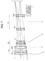
- Fig. 7 is a view showing the arrangement of a lens capable of a short distance photographing (close-up) according to the seventh embodiment of the present invention.
- the lens capable of a short distance photographing (close-up) shown in Fig. 7 is constituted by, in turn from the object side, a first lens group G1 which comprises a cemented lens of a negative meniscus lens having a convex surface facing the object side and a biconvex lens, a positive meniscus lens having a convex surface facing the object side, and a cemented lens of a negative meniscus lens having a convex surface facing the object side and a positive meniscus lens having a convex surface facing the object side, a second lens group G2 which comprises a cemented lens of a negative meniscus lens having a convex surface facing the object side and a positive meniscus lens having a convex surface facing the object side, and a cemented lens of a positive meniscus lens having a concave surface facing the object side and a bi
- the positive meniscus lens having the convex surface facing the object side constitutes a vibration reduction lens group GLP having a positive refracting power.
- an aperture stop S is arranged between the second and third lens groups G2 and GL, and a stationary flare stop FS is arranged in the third lens group GL, as shown in Fig. 7.
- the cemented lens of the negative meniscus lens having the convex surface facing the object side and the biconvex lens, and the positive meniscus lens having the convex surface facing the object side constitute a front group G11
- the cemented lens of the negative meniscus lens having the convex surface facing the object side and the positive meniscus lens having the convex surface facing the object side constitutes a rear group G12.
- Fig. 7 shows the positional relationship among the lens groups in an infinity photographing state, and when focusing is effected to a short distance, the front group G11 of the first lens group G1 and the second lens group G2 move on the optical axis along paths indicated by arrows in Fig. 7. Note that the rear group G12 of the first lens group and the third lens group GL are fixed in position in the optical axis direction.
- the vibration reduction lens group GLP as a partial lens group of the third lens group GL is appropriately moved in a direction substantially perpendicular to the optical axis by a vibration reduction mechanism 1 as the displacement means, thereby correcting a blur of an image caused by, e.g., a camera shake.
- the present invention is applied to a photograph lens having a relatively long focal length.
- Table 7 summarizes data values of the seventh embodiment of the present invention.
- f is the focal length in the infinity state
- ⁇ is the photographing magnification at a short distance
- F NO is the f-number in the infinity state
- 2 ⁇ is the field angle in the infinity state
- Bf is the back focus.
- numerals in the leftmost column represent the order of lens surfaces
- r is the radius of curvature of each lens surface
- d the lens surface interval
- a lens capable of a short distance photographing (close-up), which comprises a vibration reduction function, has a relatively long focal length, and is suitable for, e.g., a photograph, video image, and the like, can be provided.
- the lens allows a hand-held photographing operation, and is very convenient for an actual photographing operation.
- the lens realizes a photographing operation under a vibration condition caused by, e.g., a camera shake with good imaging performance.
Landscapes
- Physics & Mathematics (AREA)
- General Physics & Mathematics (AREA)
- Optics & Photonics (AREA)
- Lenses (AREA)
Priority Applications (1)
| Application Number | Priority Date | Filing Date | Title |
|---|---|---|---|
| EP98107034A EP0881516A1 (de) | 1993-11-29 | 1994-11-23 | Linse für Fotografie von kurzen Abständen mit eingebauter Funktion zur Reduktion von Vibrationen |
Applications Claiming Priority (6)
| Application Number | Priority Date | Filing Date | Title |
|---|---|---|---|
| JP323282/93 | 1993-11-29 | ||
| JP5323282A JPH07152001A (ja) | 1993-11-29 | 1993-11-29 | 防振機能を備えた近距離補正レンズ |
| JP74440/94 | 1994-03-18 | ||
| JP6074440A JPH07261127A (ja) | 1994-03-18 | 1994-03-18 | 防振機能を備えた近距離補正レンズ |
| JP74439/94 | 1994-03-18 | ||
| JP07443994A JP3531209B2 (ja) | 1994-03-18 | 1994-03-18 | 防振機能を備えた近距離補正レンズ |
Related Child Applications (1)
| Application Number | Title | Priority Date | Filing Date |
|---|---|---|---|
| EP98107034A Division EP0881516A1 (de) | 1993-11-29 | 1994-11-23 | Linse für Fotografie von kurzen Abständen mit eingebauter Funktion zur Reduktion von Vibrationen |
Publications (1)
| Publication Number | Publication Date |
|---|---|
| EP0655638A1 true EP0655638A1 (de) | 1995-05-31 |
Family
ID=27301500
Family Applications (2)
| Application Number | Title | Priority Date | Filing Date |
|---|---|---|---|
| EP98107034A Withdrawn EP0881516A1 (de) | 1993-11-29 | 1994-11-23 | Linse für Fotografie von kurzen Abständen mit eingebauter Funktion zur Reduktion von Vibrationen |
| EP94118425A Ceased EP0655638A1 (de) | 1993-11-29 | 1994-11-23 | Linse für Fotografie von kurzen Abständen mit eingebauter Funktion zur Reduktion von Vibrationen |
Family Applications Before (1)
| Application Number | Title | Priority Date | Filing Date |
|---|---|---|---|
| EP98107034A Withdrawn EP0881516A1 (de) | 1993-11-29 | 1994-11-23 | Linse für Fotografie von kurzen Abständen mit eingebauter Funktion zur Reduktion von Vibrationen |
Country Status (1)
| Country | Link |
|---|---|
| EP (2) | EP0881516A1 (de) |
Cited By (10)
| Publication number | Priority date | Publication date | Assignee | Title |
|---|---|---|---|---|
| US5654826A (en) * | 1995-04-04 | 1997-08-05 | Nikon Corporation | Zoom lens system having a vibration reduction function |
| EP0789259A2 (de) | 1996-02-08 | 1997-08-13 | Minolta Co., Ltd. | Optisches System mit eingebauter Funktion zur Reduktion von Vibrationen |
| US5737129A (en) * | 1994-12-26 | 1998-04-07 | Nikon Corporation | Wide-angle zoom lens |
| US5781340A (en) * | 1995-02-10 | 1998-07-14 | Nikon Corporation | Gauss lens with image stabilizing function |
| US5828499A (en) * | 1995-02-23 | 1998-10-27 | Nikon Corporation | Zoom lens system |
| US5831775A (en) * | 1995-03-10 | 1998-11-03 | Nikon Corporation | Long focal length microlens system |
| US7545589B2 (en) | 2005-07-14 | 2009-06-09 | Point Source Limited | Optical assembly |
| CN104871061A (zh) * | 2012-12-21 | 2015-08-26 | 富士胶片株式会社 | 摄像透镜及摄像装置 |
| CN106680977A (zh) * | 2017-03-14 | 2017-05-17 | 桂林电子科技大学 | 用于机器视觉检测的大视场长工作距无畸变复消色差镜头 |
| CN110501810A (zh) * | 2018-05-17 | 2019-11-26 | 株式会社腾龙 | 光学系统和摄像装置 |
Families Citing this family (1)
| Publication number | Priority date | Publication date | Assignee | Title |
|---|---|---|---|---|
| DE102016125402B4 (de) * | 2016-12-22 | 2018-12-20 | Carl Zeiss Ag | Kompaktes Kameraobjektiv höchster Abbildungsgüte für eine Kamera mit Vollformatsensor, Verwendung eines solchen Kameraobjektivs und Foto- oder Filmkamera mit einem solchen Kameraobjektiv |
Citations (7)
| Publication number | Priority date | Publication date | Assignee | Title |
|---|---|---|---|---|
| US4844602A (en) * | 1986-11-04 | 1989-07-04 | Canon Kabushiki Kaisha | Optical system for deflecting image |
| JPH01189621A (ja) * | 1988-01-26 | 1989-07-28 | Canon Inc | 防振機能を有した変倍光学系 |
| JPH01191112A (ja) * | 1988-01-26 | 1989-08-01 | Canon Inc | 防振機能を有した変倍光学系 |
| JPH01191113A (ja) * | 1988-01-26 | 1989-08-01 | Canon Inc | 防振機能を有した変倍光学系 |
| JPH02103014A (ja) * | 1988-10-12 | 1990-04-16 | Minolta Camera Co Ltd | 手ブレ補正光学系を有したズームレンズ |
| US5039211A (en) * | 1988-07-28 | 1991-08-13 | Asahi Kogaku Kogyo Kabushiki Kaisha | Zoom lens capable of image blur compensation |
| US5270857A (en) * | 1987-10-30 | 1993-12-14 | Canon Kabushiki Kaisha | Optical system for stabilizing an image |
Family Cites Families (3)
| Publication number | Priority date | Publication date | Assignee | Title |
|---|---|---|---|---|
| JPS56107210A (en) * | 1980-01-31 | 1981-08-26 | Nippon Kogaku Kk <Nikon> | Lens system permitting short-distance photographing |
| JPS5741608A (en) * | 1980-08-27 | 1982-03-08 | Nippon Kogaku Kk <Nikon> | Lens for closeup photographing |
| JP2679130B2 (ja) * | 1988-07-08 | 1997-11-19 | 株式会社ニコン | 近距離撮影可能なレンズ |
-
1994
- 1994-11-23 EP EP98107034A patent/EP0881516A1/de not_active Withdrawn
- 1994-11-23 EP EP94118425A patent/EP0655638A1/de not_active Ceased
Patent Citations (7)
| Publication number | Priority date | Publication date | Assignee | Title |
|---|---|---|---|---|
| US4844602A (en) * | 1986-11-04 | 1989-07-04 | Canon Kabushiki Kaisha | Optical system for deflecting image |
| US5270857A (en) * | 1987-10-30 | 1993-12-14 | Canon Kabushiki Kaisha | Optical system for stabilizing an image |
| JPH01189621A (ja) * | 1988-01-26 | 1989-07-28 | Canon Inc | 防振機能を有した変倍光学系 |
| JPH01191112A (ja) * | 1988-01-26 | 1989-08-01 | Canon Inc | 防振機能を有した変倍光学系 |
| JPH01191113A (ja) * | 1988-01-26 | 1989-08-01 | Canon Inc | 防振機能を有した変倍光学系 |
| US5039211A (en) * | 1988-07-28 | 1991-08-13 | Asahi Kogaku Kogyo Kabushiki Kaisha | Zoom lens capable of image blur compensation |
| JPH02103014A (ja) * | 1988-10-12 | 1990-04-16 | Minolta Camera Co Ltd | 手ブレ補正光学系を有したズームレンズ |
Non-Patent Citations (1)
| Title |
|---|
| PATENT ABSTRACTS OF JAPAN vol. 14, no. 317 (P - 1073) 9 July 1990 (1990-07-09) * |
Cited By (15)
| Publication number | Priority date | Publication date | Assignee | Title |
|---|---|---|---|---|
| US5737129A (en) * | 1994-12-26 | 1998-04-07 | Nikon Corporation | Wide-angle zoom lens |
| US5781340A (en) * | 1995-02-10 | 1998-07-14 | Nikon Corporation | Gauss lens with image stabilizing function |
| US5828499A (en) * | 1995-02-23 | 1998-10-27 | Nikon Corporation | Zoom lens system |
| US5831775A (en) * | 1995-03-10 | 1998-11-03 | Nikon Corporation | Long focal length microlens system |
| US5654826A (en) * | 1995-04-04 | 1997-08-05 | Nikon Corporation | Zoom lens system having a vibration reduction function |
| EP0789259A3 (de) * | 1996-02-08 | 1997-11-19 | Minolta Co., Ltd. | Optisches System mit eingebauter Funktion zur Reduktion von Vibrationen |
| EP0789259A2 (de) | 1996-02-08 | 1997-08-13 | Minolta Co., Ltd. | Optisches System mit eingebauter Funktion zur Reduktion von Vibrationen |
| US6512633B2 (en) | 1996-02-08 | 2003-01-28 | Minolta Co., Ltd | Optical system for compensation of image shake |
| US7545589B2 (en) | 2005-07-14 | 2009-06-09 | Point Source Limited | Optical assembly |
| CN104871061A (zh) * | 2012-12-21 | 2015-08-26 | 富士胶片株式会社 | 摄像透镜及摄像装置 |
| CN104871061B (zh) * | 2012-12-21 | 2017-03-08 | 富士胶片株式会社 | 摄像透镜及摄像装置 |
| CN106680977A (zh) * | 2017-03-14 | 2017-05-17 | 桂林电子科技大学 | 用于机器视觉检测的大视场长工作距无畸变复消色差镜头 |
| CN106680977B (zh) * | 2017-03-14 | 2022-06-10 | 桂林电子科技大学 | 用于机器视觉检测的大视场长工作距无畸变复消色差镜头 |
| CN110501810A (zh) * | 2018-05-17 | 2019-11-26 | 株式会社腾龙 | 光学系统和摄像装置 |
| CN110501810B (zh) * | 2018-05-17 | 2022-10-11 | 株式会社腾龙 | 光学系统和摄像装置 |
Also Published As
| Publication number | Publication date |
|---|---|
| EP0881516A1 (de) | 1998-12-02 |
Similar Documents
| Publication | Publication Date | Title |
|---|---|---|
| US6320698B1 (en) | Zoom lens with vibration reduction function | |
| US5585966A (en) | Zoom lens with vibration reduction function | |
| US7616386B2 (en) | Zoom lens and image-pickup apparatus | |
| JP3253405B2 (ja) | 2群ズームレンズ | |
| US5781340A (en) | Gauss lens with image stabilizing function | |
| JPH0354325B2 (de) | ||
| JPH083580B2 (ja) | コンパクトな高変倍率ズ−ムレンズ | |
| JPH06201988A (ja) | 大口径比内焦望遠レンズ | |
| US5751485A (en) | Lens capable of short distance photographing with vibration reduction function | |
| JP3306129B2 (ja) | 標準レンズ | |
| JP2002107616A (ja) | インナーフォーカス式のレンズ | |
| JPH05150161A (ja) | 変倍レンズ | |
| JPH07199070A (ja) | ズームレンズ | |
| EP0655638A1 (de) | Linse für Fotografie von kurzen Abständen mit eingebauter Funktion zur Reduktion von Vibrationen | |
| JPH0830783B2 (ja) | コンパクトカメラ用高変倍ズームレンズ | |
| JP3735909B2 (ja) | レトロフォーカス型レンズ | |
| JP2001337265A (ja) | フローティングを利用した撮影レンズ | |
| JPH09127415A (ja) | 2群ズームレンズ | |
| JP2001228396A (ja) | 色消しレンズおよびこれを用いたズームレンズ | |
| JP3331011B2 (ja) | 小型の2群ズームレンズ | |
| JPH06175027A (ja) | リアフォーカス式の小型ズームレンズ | |
| JP3723643B2 (ja) | 高変倍ズームレンズ系 | |
| US7161742B2 (en) | Small zoom lens, and digital camera and video camera both having same | |
| KR100189069B1 (ko) | 소형 광각 사진 렌즈 | |
| JPH0727975A (ja) | 防振機能を備えたリアコンバージョンレンズ |
Legal Events
| Date | Code | Title | Description |
|---|---|---|---|
| PUAI | Public reference made under article 153(3) epc to a published international application that has entered the european phase |
Free format text: ORIGINAL CODE: 0009012 |
|
| AK | Designated contracting states |
Kind code of ref document: A1 Designated state(s): DE FR |
|
| 17P | Request for examination filed |
Effective date: 19951019 |
|
| 17Q | First examination report despatched |
Effective date: 19971204 |
|
| RTI1 | Title (correction) |
Free format text: LENS CAPABLE OF SHORT DISTANCE PHOTOGRAPHING WITH VIBRATION REDUCTION FUNCTION |
|
| STAA | Information on the status of an ep patent application or granted ep patent |
Free format text: STATUS: THE APPLICATION HAS BEEN REFUSED |
|
| 18R | Application refused |
Effective date: 19991212 |