EP0655662B1 - Appareil de développement avec fenêtre transparente à la lumière - Google Patents
Appareil de développement avec fenêtre transparente à la lumière Download PDFInfo
- Publication number
- EP0655662B1 EP0655662B1 EP94118492A EP94118492A EP0655662B1 EP 0655662 B1 EP0655662 B1 EP 0655662B1 EP 94118492 A EP94118492 A EP 94118492A EP 94118492 A EP94118492 A EP 94118492A EP 0655662 B1 EP0655662 B1 EP 0655662B1
- Authority
- EP
- European Patent Office
- Prior art keywords
- developer
- wiping sheet
- light transmitting
- cleaning blade
- cleaning
- Prior art date
- Legal status (The legal status is an assumption and is not a legal conclusion. Google has not performed a legal analysis and makes no representation as to the accuracy of the status listed.)
- Expired - Lifetime
Links
- 238000004140 cleaning Methods 0.000 claims description 164
- 230000003287 optical effect Effects 0.000 claims description 22
- 238000001514 detection method Methods 0.000 claims description 3
- 238000003756 stirring Methods 0.000 description 20
- 238000000034 method Methods 0.000 description 19
- 230000008569 process Effects 0.000 description 19
- 239000000463 material Substances 0.000 description 10
- 230000000694 effects Effects 0.000 description 8
- 230000007423 decrease Effects 0.000 description 5
- 230000006866 deterioration Effects 0.000 description 3
- 230000000903 blocking effect Effects 0.000 description 2
- 230000003247 decreasing effect Effects 0.000 description 2
- 230000002542 deteriorative effect Effects 0.000 description 2
- 238000007599 discharging Methods 0.000 description 2
- 238000004519 manufacturing process Methods 0.000 description 2
- 238000007790 scraping Methods 0.000 description 2
- 238000000926 separation method Methods 0.000 description 2
- 238000010521 absorption reaction Methods 0.000 description 1
- 230000009471 action Effects 0.000 description 1
- 238000005054 agglomeration Methods 0.000 description 1
- 230000002776 aggregation Effects 0.000 description 1
- 230000005540 biological transmission Effects 0.000 description 1
- 230000008859 change Effects 0.000 description 1
- 210000000078 claw Anatomy 0.000 description 1
- 238000011109 contamination Methods 0.000 description 1
- 230000035553 feeding performance Effects 0.000 description 1
- 238000003384 imaging method Methods 0.000 description 1
- 230000007246 mechanism Effects 0.000 description 1
- 230000004048 modification Effects 0.000 description 1
- 238000012986 modification Methods 0.000 description 1
- 238000000465 moulding Methods 0.000 description 1
- 238000009828 non-uniform distribution Methods 0.000 description 1
- 239000002245 particle Substances 0.000 description 1
- 238000003825 pressing Methods 0.000 description 1
- 230000035945 sensitivity Effects 0.000 description 1
- 238000009827 uniform distribution Methods 0.000 description 1
Images







Classifications
-
- G—PHYSICS
- G03—PHOTOGRAPHY; CINEMATOGRAPHY; ANALOGOUS TECHNIQUES USING WAVES OTHER THAN OPTICAL WAVES; ELECTROGRAPHY; HOLOGRAPHY
- G03G—ELECTROGRAPHY; ELECTROPHOTOGRAPHY; MAGNETOGRAPHY
- G03G15/00—Apparatus for electrographic processes using a charge pattern
- G03G15/06—Apparatus for electrographic processes using a charge pattern for developing
- G03G15/08—Apparatus for electrographic processes using a charge pattern for developing using a solid developer, e.g. powder developer
- G03G15/0822—Arrangements for preparing, mixing, supplying or dispensing developer
-
- G—PHYSICS
- G03—PHOTOGRAPHY; CINEMATOGRAPHY; ANALOGOUS TECHNIQUES USING WAVES OTHER THAN OPTICAL WAVES; ELECTROGRAPHY; HOLOGRAPHY
- G03G—ELECTROGRAPHY; ELECTROPHOTOGRAPHY; MAGNETOGRAPHY
- G03G15/00—Apparatus for electrographic processes using a charge pattern
- G03G15/06—Apparatus for electrographic processes using a charge pattern for developing
- G03G15/08—Apparatus for electrographic processes using a charge pattern for developing using a solid developer, e.g. powder developer
- G03G15/0822—Arrangements for preparing, mixing, supplying or dispensing developer
- G03G15/0848—Arrangements for testing or measuring developer properties or quality, e.g. charge, size, flowability
- G03G15/0856—Detection or control means for the developer level
-
- G—PHYSICS
- G03—PHOTOGRAPHY; CINEMATOGRAPHY; ANALOGOUS TECHNIQUES USING WAVES OTHER THAN OPTICAL WAVES; ELECTROGRAPHY; HOLOGRAPHY
- G03G—ELECTROGRAPHY; ELECTROPHOTOGRAPHY; MAGNETOGRAPHY
- G03G15/00—Apparatus for electrographic processes using a charge pattern
- G03G15/06—Apparatus for electrographic processes using a charge pattern for developing
- G03G15/08—Apparatus for electrographic processes using a charge pattern for developing using a solid developer, e.g. powder developer
- G03G15/0822—Arrangements for preparing, mixing, supplying or dispensing developer
- G03G15/0848—Arrangements for testing or measuring developer properties or quality, e.g. charge, size, flowability
- G03G15/0856—Detection or control means for the developer level
- G03G15/0862—Detection or control means for the developer level the level being measured by optical means
-
- G—PHYSICS
- G03—PHOTOGRAPHY; CINEMATOGRAPHY; ANALOGOUS TECHNIQUES USING WAVES OTHER THAN OPTICAL WAVES; ELECTROGRAPHY; HOLOGRAPHY
- G03G—ELECTROGRAPHY; ELECTROPHOTOGRAPHY; MAGNETOGRAPHY
- G03G15/00—Apparatus for electrographic processes using a charge pattern
- G03G15/06—Apparatus for electrographic processes using a charge pattern for developing
- G03G15/08—Apparatus for electrographic processes using a charge pattern for developing using a solid developer, e.g. powder developer
- G03G15/0896—Arrangements or disposition of the complete developer unit or parts thereof not provided for by groups G03G15/08 - G03G15/0894
-
- G—PHYSICS
- G03—PHOTOGRAPHY; CINEMATOGRAPHY; ANALOGOUS TECHNIQUES USING WAVES OTHER THAN OPTICAL WAVES; ELECTROGRAPHY; HOLOGRAPHY
- G03G—ELECTROGRAPHY; ELECTROPHOTOGRAPHY; MAGNETOGRAPHY
- G03G2215/00—Apparatus for electrophotographic processes
- G03G2215/08—Details of powder developing device not concerning the development directly
- G03G2215/0802—Arrangements for agitating or circulating developer material
- G03G2215/085—Stirring member in developer container
- G03G2215/0852—Stirring member in developer container reciprocating
-
- G—PHYSICS
- G03—PHOTOGRAPHY; CINEMATOGRAPHY; ANALOGOUS TECHNIQUES USING WAVES OTHER THAN OPTICAL WAVES; ELECTROGRAPHY; HOLOGRAPHY
- G03G—ELECTROGRAPHY; ELECTROPHOTOGRAPHY; MAGNETOGRAPHY
- G03G2215/00—Apparatus for electrophotographic processes
- G03G2215/08—Details of powder developing device not concerning the development directly
- G03G2215/0888—Arrangements for detecting toner level or concentration in the developing device
- G03G2215/0891—Optical detection
- G03G2215/0894—Optical detection through a light transmissive window in the developer container wall
- G03G2215/0897—Cleaning of the light transmissive window
Definitions
- the present invention relates to a developing apparatus for developing an electrostatic latent image on an image bearing member usable with an image forming apparatus such as an electrophotographic apparatus, electrostatic recording apparatus or the like, as defined in the preamble of claim 1.
- a beam is introduced into a developer container for containing a developer, and the light transmitted through the container is detected to detect the presence or absence of the developer therein.
- Figure 21 shows a light transmitting type, wherein reference numerals 115 and 116 designate a light emitting element and light receiving element, respectively.
- a developer container 125 is provided with a transparent window 126a and a transparent window 126b for transmitting the light at the position corresponding to light emitting element 115 and light receiving element 116.
- the light from the light emitting element 115 having entered the developer container 125 through transparent window 126a is blocked by the developer therein, so that the light will not reach the light receiving element 116.
- the developer container becomes empty by the consumption of the developer, the light from the light emitting element 115 reaches the light receiving element 116 through the transparent window 126a and transparent window 126b. In this manner, the presence or absence of the developer is detected on the basis of the change of the output of the light receiving element 116.
- Figure 22 is an enlarged view of a cleaning member 129 for cleaning the windows. It is rotatable about shaft 129a by an unshown driving source. A cleaning blade 128 of flexible material is mounted to a tip end of the cleaning member 129 and is brought into contact with the inside surfaces of the transparent window 126a and transparent window 126b and wipes the developer T thereon out, with rotation of the cleaning member 129. By doing so, it is avoided that the erroneous discrimination of presence of the developer due to the contamination of the windows, despite the absence of the developer.
- Patent Abstracts of Japan, vol. 14, no. 124 (P-1018); & JP-A-1 319 065 discloses such a developing apparatus comprising a wiping sheet fixed to a rotatable cleaning member.
- the contact angle is preferably 90 degrees.
- the contact angle is very close to 90 degrees, the blade does not reach to the window surface, if it is even slightly shorter than required with the result of the liability of incapability of the cleaning. The result is that the positioning between the window surface and the blade is highly accurate. This increases a manufacturing cost of the apparatus. Additionally, if the contact angle is very close to 90 degrees, and if the blade is deformed even slightly by the resistance caused by the scraping action, the cleaning of the window becomes not possible.
- the sufficient entrance amount d of the blade and the contact angle are determined in consideration of the positional accuracy and the deformation of the apparatus.
- the entrance amount of the blade d has to be reduced, with the result of the following problems.
- d>0 is required even if the d is small, and therefore, the positional precision is required, which leads to the increase of the cost.
- the entrance amount is too large, the contact angle becomes small, the cleaning effects are deteriorated.
- the deformation of the blade increases, the difference in the torque required when the blade is cleaning the window surface and that when the blade is out of contact to the window surface increases. This increases the variation of the torque during the image forming operation with the possible result of the deterioration of the quality of the resultant image.
- Figure 1 is a perspective view of an image forming apparatus according to an embodiment of the present invention.
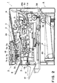
- Figure 2 is a longitudinal sectional view of an image forming apparatus of embodiment 1.
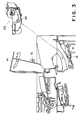
- Figure 3 illustrates an operation of mounting and demounting a process cartridge relative to the image forming apparatus of embodiment 1.
- Figure 4 is a front view of a cleaning member used in the apparatus of embodiment 1.
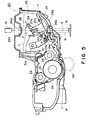
- Figure 5 is a longitudinal sectional view of a process cartridge according to embodiment 1.
- Figure 6 is a perspective view of a major portion of a process cartridge according to embodiment 1.
- Figure 7 illustrates modified example of the cleaning blade in embodiment 1.
- Figure 8 shows a cleaning blade used in embodiment 1.
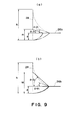
- Figure 9 schematically shows a relationship between the contact angle of the cleaning blade to the transparent window and the position of the low rigidity portion of the cleaning blade in embodiment 1.
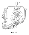
- Figure 10 shows a relationship among stirring blades, transparent window and the cleaning blade in embodiment 1.
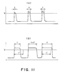
- Figure 11 schematically shows an output signal of a light receiving element in embodiment 1.
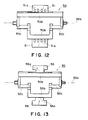
- Figure 12 shows a cleaning member in embodiment 2.
- Figure 13 shows a cleaning member in embodiment 3.
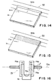
- Figure 14 shows a cleaning member in embodiment 4.
- Figure 15 shows a cleaning member in embodiment 5 (not covered by the present invention).
- Figure 16 shows a cleaning member in embodiment 6.
- Figure 17 is a longitudinal sectional view of a process cartridge in embodiment 6.
- Figure 18 is a longitudinal sectional view of a process cartridge in embodiment 6.
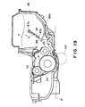
- Figure 19 is a longitudinal sectional view of a process cartridge in embodiment 7.
- Figure 20 is a perspective view of stirring blades in embodiment 7.
- Figure 21 is a longitudinal sectional view of a process cartridge.
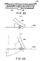
- Figure 22 is a perspective view of stirring blades used in Figure 21 structure.
- Figure 23 shows a relationship between the contact angle of the cleaning blade and the wiping force for the developer.
- the exemplary image forming apparatus taken in the embodiment is an electrophotographic type facsimile machine.
- a top cover of the main assembly of the apparatus 1 is constructed to permit to place a stack of original documents thereon. Adjacent one end of the top surface (left-hand side in Figure 2), an optical reader 3 for reading image information of an original fed from the original platen 2, above the reader 3, an operation panel 18 is provided. Below the reader 3, a recording system comprising a laser beam printer is located.
- the optical reader 3 separates one by one the originals D on the original platen 2 by a prefeeding roller 5b press-contacted to a prefeeding pressing member 5a and a separation roller 5d press-contacted to a reversing roller 5c, and feeds it to a contact sensor by original feeding roller pair 5e or the like.
- the image information of the original D is read while an urging means presses the original D onto the contact sensor 7, and thereafter, the original D is discharged to the discharge tray 8 by discharging pair of rollers 5f.
- the contact sensor 7 emits light to the image information of the originals from LED 7a functioning as a light source, and the light reflected thereby is imaged on a photo-electric converter 7c through a short focus imaging lens 7b.
- the read information is transmitted to a recording station of another machine in a facsimile mode and is transmitted to a recording system of itself in a copy mode.
- Original platen 2 is provided with a slider 2a slidable in a direction perpendicular to a feeding direction of an original (width direction of the original D).
- the slider 2 is operated to meet the width of the original to align the lateral edges of the originals.
- a laser beam oscillator 9a of the recording system 4 emits a laser beam modulated in accordance with the image signals of the contact sensor 7, and the modulated beam is deflected by a polygonal mirror 9b and is directed to a photosensitive drum 21 in an image forming station as image light.
- the image information is converted to an toner image, which in turn is transferred onto a recording sheet p', and fixed thereon. Then, the recording sheet p' is discharged.
- the photosensitive drum 21 is integrally contained in a process cartridge 20 together with a primary charger 22, a developing device 23, a cleaner 24 and a developer container 25 for containing a developer T, and the process cartridge is detachably mountable to the main assembly 1 of the apparatus.
- the image forming operation will be described.
- the surface of the photosensitive drum 21 (image bearing member) is uniformly changed by the primary charger 22, and is subjected to the image light L from the laser beam oscillator 9a, by which an electrostatic latent image is formed on the photosensitive drum 21.
- the electrostatic latent image is visualized into a toner image by the developer (toner T) supplied from the developing device 23.
- the toner image on the photosensitive drum 21 is transferred onto a recording sheet p' fed from a sheet feeder A, by a transfer charger 10 disposed adjacent to the photosensitive drum 21.
- the recording sheet p' now carrying the toner image is subjected to image fixing of an image fixing device 10g so that the toner image is fixed on the sheet.
- the sheet is discharged discharging pair of rollers 11h to a discharge tray 12 detachably mounted to a sides of an apparatus (left side in Figures 2 and 3).
- the photosensitive drum 21 after the image transfer operation is cleaned by the cleaner 24 so that the residual toner or the like is removed, thus preparing for the next image forming operation.
- process cartridge 20 can be removed and exchanged.
- the process cartridge 20 is provided with a shutter 30 for blocking it from the light.
- the shutter 30 automatically opens when the process cartridge is mounted in the apparatus, and the shutter 30 automatically closes when it is taken out of the apparatus.
- a light emitting element 15 is mounted on an inside surface of the top part, and a light receiving element 16 is mounted on the main assembly of the apparatus. They are so disposed that when the process cartridge 20 is mounted to the main assembly 1 and the cover 14 is closed, they are faced with the developer container 25 therebetween.
- the developer container 25 is provided with a transparent window 26a and a transparent window 26b interposed between the light emitting element 15 and light receiving element 16.
- the detecting light emitted by light emitting element 15 is directed into the developer container 25 through the transparent window 26a.
- the developer container 25 contains a sufficient amount of the developer T
- the light is blocked by the developer T.
- the developer container 25 does not contain the developer T
- the light passes through the transparant window 26b to the outside of developer container 25 to reach the light receiving element 16, so that the absence of the developer T can be detected.
- a topmost one of the sheets stacked on a cassette 40 which is retractable from one side of the bottom portion of the apparatus is fed out by cooperation of separation claws 41 at the front corners and a crescent pick-up roller 36.
- the sheet is then fed to a feeding roller as a pair of registration roller, by a pair of feeding rollers 38.
- the registration roller feeds the sheet, in timed relation with the leading edge of the toner image on the photosensitive drum 21, to the image transfer position formed by a transfer charger 10f and the photosensitive drum 21.
- Figure 4 is a front view of a cleaning member according to an embodiment of the present invention.
- Figures 5 and 6 are longitudinal sectional view and a perspective view of a major part of the developer detector.
- the light emitting element 15 and light receiving element 16 are mounted on the main assembly 1 so that they are faced to each other.
- Designated by S is an optical axis connecting therebetween, and R is an optical path of the detecting light incident on the light receiving element 16.
- the transparent window 26a and transparant window 26b are formed in a top wall 25a and a bottom wall 25b of the developer container 25.
- transparent means transparent relative to the light or beam emitted by the light emitting element 15, and does not necessarily means “visually transparent”.
- a stirring blade 27 and a stirring arm 31 are provided in the developer container 25.
- a shaft 27a adjacent an end of the stirring blade 27 is engaged with a hole 31a of stirring arm 31.
- Stirring blade 27 has an opening 27b so as not to interfere with the optical path R, and ribs 27c provided with U-grooves are formed at both sides thereof.
- Stirring arm 31 is rotatably supported on a shaft 31b on a side of the developer container 25. An end thereof extends outwardly from the side of the developer container 25, and an end portion thereof is provided with an integral driving arm 31c.
- a stirring gear 32 is mounted to the outside of developer container 25, and rotates about shaft 32a with the rotation of the photosensitive drum 21.
- a pin 32b is eccentric from the shaft 32a, and is engaged with a hole 31d of the driving arm 31c.
- the stirring arm 31 reciprocates in direction X about the shaft 31b.
- the stirring blade 27 reciprocates in direction Y along the bottom of the developer container 25 to feed the developer T into a developing chamber and to prevent agglomeration of the developer T or the non-uniform distribution of the developer T in the developer container 25.
- the bottom wall 25b of the developer container 25 is slanted toward the developing chamber to assist the supply of the developer T to the developing chamber.
- a cleaning member 29 is for cleaning the transparent window 26a and transparant window 26b, and is rotatably supported on shaft 29a.
- a driving shaft 29c is an eccentric driving shaft eccentric from the shaft 29a, and is engaged in the U-groove of the stirring blade 27.
- the driving shaft 29c receives force from a rib 27c, to reciprocally swing the cleaning member 29 about shaft 29a in a direction Z.
- the angle of the swinging motion is preferably less than 100 degree to permit smooth sliding between driving shaft 29c and rib 27c.
- a cleaning blade 28 is in the form of a wiping sheet of flexible material, and is fixed on the cleaning member 29 on substantially a central portion 28b of the cleaning blade 28, the opposite end portions are extended out through slits 29d formed in the end portions 29b of the cleaning member 29.
- An opening 28c is formed in the cleaning blade 28 so that the cleaning blade 28 continues to block the optical path R.
- the optical path R is blocked only when the the end portion 29b and the cleaning blade 28 are in the center of the path R, despite the fact that the shaft 29a is disposed at a position blocking the optical axis. Therefore, the presence or absence of the developer T can be detected when the end portions 29b or the cleaning blade 28 blocks the optical path R.
- Figure 7 shows a comparison between a modification of the cleaning blade shown in Figure 21 and that of this embodiment.
- the cleaning blade deforms significantly adjacent opening 28c as shown in Figure 7, (b) because of the provision of the opening 28c in the cleaning blade in this embodiment.
- the deformation in the other position is less.
- the entrance amount d is not required to correspondingly reduced at the same proportional ratio, and positional accuracy is not required to be increased.
- the length of the free portion of the cleaning blade can be increased as compared with the case wherein the downsizing is accomplished by mounting a short cleaning blade 128 on the end of the cleaning member 129.
- the opening 28c is effective to decrease the rigidity of the cleaning blade 28, and therefore, the rigidity of cleaning blade 28 can be reduced to maintain the low resistance against deformation of the cleaning blade 28. Because of this, there is no need of increasing the driving torque of the apparatus, and there is no liability of deteriorating the image quality. In addition, the integral structure of the two blades, the number of assembling step is decreased.
- the rigidity and the deforming portion of the cleaning blade 28 can be controlled relatively freely by changing the fixed length l 1, that is, by changing the free length l 2, or by changing the width w1 of the opening 28c, that is, the width w2 of the narrow portion of the cleaning blade.
- the opening 33c of the cleaning blade 33 may take such a configuration that the deformation of the cleaning blade is more concentrated.
- the contact pressure and the contact angle between the window surface and the cleaning blade can be determined to provide the satisfactory cleaning. Therefore, the design latitude for the entrance amount or the mounting position of the cleaning blade or another structure can be increased.
- the contact angle ⁇ can be increased ( ⁇ 2 > ⁇ 1) without changing the entrance amount d by making a distance M from the end of the cleaning blade to the low rigidity portion larger than the m satisfying the above equation. Additionally, when the contact angle equal to that without the provision of the low rigidity portion in the cleaning blade is to be obtained, the entrance amount d can be increased by making the distance M beyond m.
- the description will be made as to the relation among the light emitting element 15, light receiving element 16, transparent window 26a, transparant window 26b and cleaning member 29.
- the light emitting element 15 and light receiving element 16 are mounted to the main assembly 1 so that they are faced to each other with the developer container 25 therebetween when the process cartridge 20 is mounted to the main assembly 1.
- the shaft 29a of the cleaning member is adjacent the optical axis S, preferably, across the optical axis S.
- the transparent window 26a and transparant window 26b are faced to the transparent window 26a and transparant window 26b, respectively, and the transparent window 26a and transparant window 26b are so positioned that they are contacted by the cleaning member moving along a circumference of a circle about the shaft 29a. Therefore, the angle formed between the window surface and the optical axis S is very close to 90 degrees.
- the sizes of the transparent window 26a and transparant window 26b can be minimized as compared with the slanted window surface relative to the optical axis S. This is effective to minimize the deterioration of the image quality and the deterioration o the photosensitive drum 21 and the developer T attributable to the astray light.
- the optical path length through the material of the window is shorter than that in the case of the slanted window, and therefore, the loss of the light energy due to the absorption or the scattering or the like by the material of the window can be suppressed.
- the 90 degrees incidence of the light from the light emitting element 15 can suppress the loss of light energy due to the reflection of the light by the surface. This eliminates the necessity for the use of a light emitting element of high intensity and wide directivity or the use of high sensitivity light receiving element, thus reducing the cost of the apparatus.
- a distance H' between the bottom transparent window 26a and the shaft 29a of the cleaning member, a distance I' between the bottom end 29b of the cleaning member and the shaft 29a and a distance J' between the bottom end to the cleaning blade 28 and the shaft 29a satisfy I' ⁇ H' ⁇ J', as shown in Figure 10.
- the cleaning blade 28 is contacted to the window surfaces of the transparent window 26a and transparant window 26b while it swings, to wipe the developer T off the window surfaces thereof. Since the window surfaces are in contact with a circle having a center at the cleaning member 29 at this time, the transparent window 26a and transparant window 26b can be cleaned uniformly.
- the contact angle can be maintained without reducing the entrance amount d at the same ratio. It is also possible to maintain the resistance against the deformation of the cleaning blade 28, and the cleaning of the transparent window can be effected without increasing the driving torque and without deteriorating the image quality. It is not necessary to handle a thin and small blade so that the assembling of the apparatus is easy, and the number of the blade mounting steps can be reduced, thus reducing the manufacturing cost.
- cleaning member 29 rotates to that the cleaning blade 28 removes the developer T from the transparent window 26a and transparant window 26b.
- the developer T covers the window surfaces immediately after the cleaning blade 28 removes the developer T from the transparent window 26a and transparant window 26b, and therefore, the light from the light emitting element 15 does not reach the light receiving element 16, or even if it reach the light receiving element 16, it is quickly re-blocked. If, however, the amount of the developer T decreases, the time required for the developer T to cover the transparent window 26a and transparant window 26b.
- the developer T is used up, the the light reaches the light receiving element 16 except when the transparant window 26b and the cleaning blade 28 crosses the optical path R.
- Figure 11 shows the output signals from the light receiving element 16, wherein the coordinate represents the output and the abscissa represents the time.
- the output signal of the light receiving element 16 takes alternately a high level and low level (sew teeth).
- the time period of the high level is short (a)
- the time period thereof becomes long (b).
- the time period t for which the level is higher than a predetermined level V is detected, and the absence of the developer T is discriminated when the period t is longer than a predetermined period t'.
- the cleaning blade of a flexible material is provided with an opening, so that the rigidity of the cleaning blade is maintained low, and simultaneously, the deformation of the cleaning blade is concentrated on a predetermined position, by which even if the size of the cleaning member is reduced, the contact angle of the cleaning blade can be made larger without reducing the entrance amount of the cleaning blade.
- Figure 12 is a front view of the a cleaning member used in this embodiment.
- the transparent window 51 is cleaned by a plurality of cleaning blades 51, and the cleaning blades 51 have at least one opening 51a.
- Designated by a reference numeral 50a is a rotational shaft for the cleaning member, and 50c is a driving shaft of the cleaning member.
- This embodiment is the same as the foregoing embodiment in the other respects.
- the cleaning member 50 is used in place of the cleaning member 29, by which the driving shaft 50c receives force from the rib 27c of the stirring blade 27 so that the cleaning member 50 swings about the rotational shaft 50a to clean the transparent window 26a and transparant window 26b.
- the cleaning blade deforms significantly adjacent the opening 51a, and the deformation of the other portion is not.
- the provision of the opening 51a is effective to decrease the rigidity of the cleaning blades 51.
- the rigidity of the cleaning blade and the contact angle between the edge of the cleaning blades 51 and the transparent window 26a or transparant window 26b can be properly selected as in embodiment 1.
- the same advantageous effects as in embodiment 1 can be provided even if the free length of the cleaning blade 51 is increased.
- FIG. 13 a third embodiment of the present invention will be described As shown in Figure 13, a cleaning blade 56 having a partial narrow portion in place of the cleaning blade 51 of the foregoing embodiment. The narrowed portion is indicated by 56a.
- the structures of this embodiment are the same as embodiment 2 in the other respects.
- the cleaning blade significantly deforms adjacent the narrow portion 56a, and the deformation of the other portion is not significant.
- the provision of the narrow portion 56a is also effective to decrease the rigidity of the cleaning blade 56.
- the rigidity of the cleaning blade and the contact angle between the edge of the cleaning blade 56 and the transparent window 26a or transparant window 26b can be properly selected as in embodiment 1.
- the same advantageous effects as in embodiment 1 can be provided even if the free length of the cleaning blade 56 is increased.
- the cleaning blade 61 mounted to an end 50b of the cleaning member 50 is provided with a thin portion 61a parallel with the rotational shaft 50a for the unshown cleaning member.
- the structures of this embodiment is the same as the second embodiment in the other respects.
- the cleaning blade deforms significantly t the a thin portion 61a, and the other portion does not.
- the provision of the a thin portion 61a the rigidity of the cleaning blade 61 becomes small.
- the rigidity of the cleaning blade and the contact angle between the edge of the cleaning blade 61 and the transparent window 26a or transparant window 26b can be properly selected as in embodiment 1.
- the same advantageous effects as in embodiment 1 can be provided even if the free length of the cleaning blade 61 is increased.
- a cleaning blade 71 having a partial different material portion is used in place or the cleaning blades 51 in embodiment 2.
- the cleaning blade 71 mounted to an end 50b of the cleaning member 50 is provided with a portion of a material having a low rigidity at a base portion 71a of the cleaning blade.
- the interface between the different material portions is preferably extended substantially in parallel with the rotational shaft 50a.
- the other structures of this embodiment is the same as those of the embodiment 2.
- the cleaning blade deforms significantly adjacent the base portion of the cleaning blade, and the deformation of the other portion is not significant.
- the rigidity of the cleaning blade 71 is small.
- the rigidity of the cleaning blade and the contact angle between the edge of the cleaning blade 71 and the transparent window 26a or transparant window 26b can be properly selected as in embodiment 1.
- the same advantageous effects as in embodiment 1 can be provided even if the free length of the cleaning blade 71 is increased.
- the cleaning blade can be made by bonding of different materials or by two-color molding.
- Figures 16 and 17 are front view of the cleaning member of this embodiment and a longitudinal sectional view of a process cartridge of this embodiment, respectively.
- a cleaning blade 76 is fixed to a cleaning member 75 at an end 76b, and is supported by the end 75b of the cleaning member.
- the cleaning blade is provided with an opening 76a.
- the cleaning member 75 rotates by an unshown driving source about a shaft 75a in a direction F to clean the transparent window 26a and transparant window 26b.
- a stirring blade 77 feeds the developer T into a developing chamber through a mechanism as in embodiment 1.
- the structures of this embodiment is the same as in embodiment 1 in the other respects.
- the cleaning blade deforms significantly adjacent the opening 76a, and the deformation of the other portion is not significant .
- the provision of the opening 76a is effective to decrease the rigidity of the cleaning blade 76.
- the rigidity of the cleaning blade and the contact angle between the edge of the cleaning blade 76 and the transparent window 26a or transparant window 26b can be properly selected as in embodiment 1.
- the same advantageous effects as in embodiment 1 can be provided even if the free length of the cleaning blade 76 is increased.
- the fixed portion 76b of the cleaning blade 76 is located away from the edge of the cleaning blade beyond the rotational axis 75a of the cleaning member, with the result of longer free length.
- the fix position 76 b may be between the rotational axis of the cleaning member and the end of the cleaning blade or at the rotational center to the cleaning member.
- the presence or absence of the developer T is detected by light transmission type sensor, but reflection type is usable wherein the presence or absence of the developer T is detected by a reflection type sensor in the process cartridge. In such a case, only one transparent window is provided, and the cleaning member 80 cleans only one window 26b.
- FIG 19 is a sectional view of a process cartridge according to this embodiment
- Figure 20 is a perspective view of a stirring means which is a developer feeding means in this embodiment.
- Designated by 87 is a stirring blade, and is rotated in a direction G about a shaft 87a to feed the developer T into a developing chamber and to accomplish uniform distribution of the developer T.
- the bottom wall 85b of the developer container 85 is formed into a cylindrical shape with a center of the shaft 87a.
- a flexible blade 88 for feeding the developer T is mounted to the end 87b of the blade. With the rotation of the blade 87, the feeding blade 88 rotates while being in contact with the bottom wall 85 of the developer container to scrape the developer T deposited on the bottom wall 85b of the developer container and feed it to the developing chamber.
- the blade 88 is provided with a plurality of openings 88a at regular intervals in parallel with the shaft 87a of the stirring blade.
- the contact angle between the feeding blade and the developer container can be properly selected without the necessity of reducing the entrance amount d correspondingly at the proportional ratio. Therefore, the developer T can be fed to the developer chamber to the final end so that the process cartridge can be down sized while maintaining the conventional developer feeding performance.
Landscapes
- Physics & Mathematics (AREA)
- General Physics & Mathematics (AREA)
- Dry Development In Electrophotography (AREA)
- Cleaning In Electrography (AREA)
Claims (13)
- Appareil de développement comportant :caractérisé en ce queun récipient (25) à développateur destiné à contenir un développateur ;une partie (26a, 26b) de transmission de lumière, dans ledit récipient (25) à développateur, destinée à détecter optiquement le développateur ; etune feuille d'essuyage (28, 33, 51, 56, 61, 71, 76, 88) destinée à essuyer ladite partie (26a, 26b) de transmission de lumière ; ladite feuille d'essuyage (28, 33, 51, 56, 61, 71, 76, 88) étant fixée sur un élément rotatif (29) de nettoyage suivant une ligne parallèle à un axe de rotation dudit élément rotatif de nettoyage,
ladite feuille d'essuyage comporte une partie à faible rigidité procurée par une ouverture ou une partie découpée entre la position de fixation avec ledit élément de nettoyage et un bord distal de ladite feuille d'essuyage. - Appareil selon la revendication 1, dans lequel ladite feuille d'essuyage comporte une partie étroite (56a) formée dans ladite partie à faible rigidité.
- Appareil selon la revendication 1, dans lequel une distance M comprise entre le bord distal de ladite feuille d'essuyage (28, 33, 51, 56, 61, 71, 76, 88) et la position de la partie à faible rigidité, une longueur N comprise entre la position de fixation de ladite feuille d'essuyage (28, 33, 51, 56, 61, 71, 76, 88) et son bord distal, et une distance d'entrée d de ladite feuille d'essuyage (28, 33, 51, 56, 61, 71, 76, 88) dans la partie (26a, 26b) de transmission de lumière satisfont à :
M>m,
où m satisfait à : - Appareil selon la revendication 1, dans lequel l'ouverture (28c, 33c, 51a, 76a, 88a) transmet de la lumière pour la détection du développateur.
- Appareil de formation d'images comportant :caractérisé en ce queun élément (21) porteur d'image destiné à porter une image électrostatique ;un dispositif de développement (23) destiné à développer l'image électrostatique sur ledit élément (21) porteur d'image, ledit dispositif de développment (23) comprenant un récipient (25) à développateur destiné à contenir un développateur ; une partie (26a, 26b) de transmission de lumière dans ledit récipient (25) à développateur, destinée à détecter optiquement le développateur ; une feuille d'essuyage (28, 33, 51, 56, 61, 71, 76, 88) destinée à essuyer ladite partie (26a, 26b) de transmission de lumière ; ladite feuille d'essuyage (28, 33, 51, 56, 61, 71, 76, 88) étant fixée sur un élément rotatif (29) de nettoyage suivant une ligne parallèle à un axe de rotation dudit élément rotatif de nettoyage ;un axe optique (R) pour la détection du développateur à travers ladite partie (26a, 26b) de transmission de la lumière ; etun élément optique (15, 16) pour la détection d'un développateur à travers ladite partie (26a, 26b) de transmission de lumière,
ladite feuille d'essuyage comporte une partie à faible rigidité procurée par une ouverture ou une partie découpée entre la position de fixation dudit élément de nettoyage et un bord distal de ladite feuille d'essuyage. - Appareil selon la revendication 5, dans lequel ledit dispositif de développement (23) peut être monté de façon amovible sur un ensemble principal dudit appareil.
- Appareil selon la revendication 5, dans lequel ledit appareil détecte la présence ou l'absence du développateur sur la base d'un signal de sortie dudit élément optique (15, 16).
- Appareil selon la revendication 5, dans lequel ledit élément optique (15) émet de la lumière vers la partie (26a, 26b) de transmission de lumière.
- Appareil selon la revendication 5, dans lequel ledit élément optique (16) reçoit de la lumière de la partie (26a, 26b) de transmission de lumière.
- Appareil selon la revendication 6, dans lequel ledit dispositif de développement (23) est relié structurellement audit élément (21) porteur d'image pour constituer une cartouche (20).
- Appareil selon la revendication 5, dans lequel ladite feuille d'essuyage comporte une partie étroite (56a) formée dans ladite partie à faible rigidité.
- Appareil selon la revendication 7, dans lequel une distance M entre le bord distal de ladite feuille d'essuyage (28, 33, 51, 56, 61, 71, 76, 88) et la position de la partie à faible rigidité, une longueur N entre la partie de fixation de ladite feuille d'essuyage (28, 33, 51, 56, 61, 71, 76, 88) et son bord distal, et une distance d'entrée d de ladite feuille d'essuyage (28, 33, 51, 56, 61, 71, 76, 88) dans la partie (26a, 26b) de transmission de lumière satisfont à :
M>m,
où m satisfait à - Appareil selon la revendication 5, dans lequel l'ouverture transmet de la lumière pour la détection du développateur.
Applications Claiming Priority (3)
| Application Number | Priority Date | Filing Date | Title |
|---|---|---|---|
| JP317547/93 | 1993-11-25 | ||
| JP31754793 | 1993-11-25 | ||
| JP31754793A JP3198002B2 (ja) | 1993-11-25 | 1993-11-25 | 現像装置、プロセスカートリッジ及び画像形成装置 |
Publications (3)
| Publication Number | Publication Date |
|---|---|
| EP0655662A2 EP0655662A2 (fr) | 1995-05-31 |
| EP0655662A3 EP0655662A3 (fr) | 1996-12-04 |
| EP0655662B1 true EP0655662B1 (fr) | 1999-09-22 |
Family
ID=18089478
Family Applications (1)
| Application Number | Title | Priority Date | Filing Date |
|---|---|---|---|
| EP94118492A Expired - Lifetime EP0655662B1 (fr) | 1993-11-25 | 1994-11-24 | Appareil de développement avec fenêtre transparente à la lumière |
Country Status (5)
| Country | Link |
|---|---|
| US (1) | US5655175A (fr) |
| EP (1) | EP0655662B1 (fr) |
| JP (1) | JP3198002B2 (fr) |
| DE (1) | DE69420816T2 (fr) |
| ES (1) | ES2136152T3 (fr) |
Families Citing this family (17)
| Publication number | Priority date | Publication date | Assignee | Title |
|---|---|---|---|---|
| EP0665475A3 (fr) * | 1994-01-28 | 1997-01-29 | Canon Kk | Appareil de développement, unité de traitement, appareil de formation d'images et méthode d'assemblage d'une unité de traitement. |
| KR0174688B1 (ko) * | 1996-06-26 | 1999-04-01 | 김광호 | 현상기 토너 공급장치 |
| JP3239258B2 (ja) * | 1996-07-04 | 2001-12-17 | 京セラミタ株式会社 | 攪拌器及びこれを備えたトナーカートリッジ |
| KR200145744Y1 (ko) * | 1996-09-10 | 1999-06-15 | 윤종용 | 현상기 내부의 토너량 유.무 감지장치 |
| JP3736116B2 (ja) * | 1998-05-01 | 2006-01-18 | 村田機械株式会社 | 画像記録装置 |
| US6456810B1 (en) * | 1999-07-14 | 2002-09-24 | Brother Kogyo Kabushiki Kaisha | Developing cartridge having toner agitator agitating toners in toner container and transferring toner to developing chamber |
| JP2001350339A (ja) * | 2000-06-02 | 2001-12-21 | Brother Ind Ltd | 現像カートリッジおよび画像形成装置 |
| JP3926317B2 (ja) * | 2003-11-28 | 2007-06-06 | シャープ株式会社 | トナー残量検出装置、及びそれを備える画像形成装置 |
| JP2006154001A (ja) * | 2004-11-25 | 2006-06-15 | Ricoh Co Ltd | 現像装置、及びこれを備えたプロセスカートリッジ、画像形成装置 |
| WO2006079162A1 (fr) * | 2005-01-25 | 2006-08-03 | Gcc Ip Pty Ltd | Appareil de nettoyage de fenetre de detection de toner |
| DE602006021255D1 (de) | 2005-04-26 | 2011-05-26 | Brother Ind Ltd | Entwicklungskartusche für eine Bilderzeugungsvorrichtung |
| JP4630166B2 (ja) * | 2005-09-27 | 2011-02-09 | 株式会社沖データ | 現像剤収容装置、現像装置、及び画像形成装置 |
| JP4563329B2 (ja) * | 2006-03-08 | 2010-10-13 | 京セラミタ株式会社 | 現像装置 |
| JP5022726B2 (ja) * | 2006-09-19 | 2012-09-12 | 株式会社リコー | 検知窓のトナー付着防止装置、トナー補給装置および画像形成装置 |
| JP4935277B2 (ja) * | 2006-09-28 | 2012-05-23 | ブラザー工業株式会社 | 画像形成装置 |
| USD903504S1 (en) | 2018-06-11 | 2020-12-01 | Ecolab Usa Inc. | Pouch container |
| US10642189B2 (en) * | 2018-07-31 | 2020-05-05 | Canon Kabushiki Kaisha | Developer container unit, developing apparatus, and process cartridge |
Family Cites Families (3)
| Publication number | Priority date | Publication date | Assignee | Title |
|---|---|---|---|---|
| JPS632087A (ja) * | 1986-06-23 | 1988-01-07 | Toshiba Corp | 現像装置 |
| JPS6438779A (en) * | 1987-08-05 | 1989-02-09 | Minolta Camera Kk | Cleaning device for toner detecting sensor |
| JP2606886B2 (ja) * | 1988-06-20 | 1997-05-07 | キヤノン株式会社 | 像形成カートリッジ及び該像形成カートリッジを装着可能な画像形成装置 |
-
1993
- 1993-11-25 JP JP31754793A patent/JP3198002B2/ja not_active Expired - Fee Related
-
1994
- 1994-11-24 ES ES94118492T patent/ES2136152T3/es not_active Expired - Lifetime
- 1994-11-24 EP EP94118492A patent/EP0655662B1/fr not_active Expired - Lifetime
- 1994-11-24 DE DE69420816T patent/DE69420816T2/de not_active Expired - Fee Related
-
1996
- 1996-07-22 US US08/684,625 patent/US5655175A/en not_active Expired - Lifetime
Also Published As
| Publication number | Publication date |
|---|---|
| US5655175A (en) | 1997-08-05 |
| EP0655662A3 (fr) | 1996-12-04 |
| JPH07146610A (ja) | 1995-06-06 |
| DE69420816D1 (de) | 1999-10-28 |
| EP0655662A2 (fr) | 1995-05-31 |
| JP3198002B2 (ja) | 2001-08-13 |
| ES2136152T3 (es) | 1999-11-16 |
| DE69420816T2 (de) | 2000-04-20 |
Similar Documents
| Publication | Publication Date | Title |
|---|---|---|
| US5655175A (en) | Developing apparatus having light transmitting window | |
| KR100975447B1 (ko) | 현상 장치, 프로세스 카트리지 및 화상 형성 장치 | |
| KR100303763B1 (ko) | 현상카트리지및전자사진화상형성장치 | |
| US6496662B1 (en) | Optical toner low sensor | |
| US7903994B2 (en) | Image forming apparatus | |
| US5682574A (en) | Developing apparatus having reciprocating cleaning device for photodetector | |
| JPH07219413A (ja) | プロセスカートリッジ及び画像形成装置及びプロセスカートリッジの組立方法 | |
| EP1471380A2 (fr) | Réservoir d'alimentation en développateur | |
| US6256459B1 (en) | Developing apparatus and image forming apparatus using the same developing apparatus and method of determining end-of-toner condition | |
| CN100520622C (zh) | 显影剂装置和成像设备 | |
| US20090274478A1 (en) | Image forming apparatus and sensing device thereof | |
| US7756432B2 (en) | Image forming apparatus and cartridge having optical detection of toner amount | |
| US5063409A (en) | Image recording apparatus and exchanging unit used in the same | |
| US7742708B2 (en) | Image forming device and cartridge in which an amount of developer is detectable | |
| US20030103254A1 (en) | Scanning device and image forming apparatus | |
| HK1014055A (en) | Developing apparatus having light transmitting window | |
| JP2891871B2 (ja) | 現像剤有無検知装置および現像ユニット | |
| US5953569A (en) | Toner supply roller for use in image forming device | |
| JP2002040891A (ja) | 現像剤容器の着脱状況の判断方法及び画像形成装置 | |
| JP3143541B2 (ja) | カートリッジ及び画像形成装置 | |
| JPH0626927Y2 (ja) | 画像形成装置 | |
| JP4497992B2 (ja) | 現像剤補給容器 | |
| JPH07219412A (ja) | 現像装置及びプロセスカートリッジ及び画像形成装置及びプロセスカートリッジの組立方法 | |
| JPH07219323A (ja) | 現像装置及びプロセスカートリッジ及び画像形成装置及びプロセスカートリッジの組立方法 | |
| JPH0850440A (ja) | 電子写真装置 |
Legal Events
| Date | Code | Title | Description |
|---|---|---|---|
| PUAI | Public reference made under article 153(3) epc to a published international application that has entered the european phase |
Free format text: ORIGINAL CODE: 0009012 |
|
| 17P | Request for examination filed |
Effective date: 19941124 |
|
| AK | Designated contracting states |
Kind code of ref document: A2 Designated state(s): DE ES FR GB IT |
|
| PUAL | Search report despatched |
Free format text: ORIGINAL CODE: 0009013 |
|
| AK | Designated contracting states |
Kind code of ref document: A3 Designated state(s): DE ES FR GB IT |
|
| 17Q | First examination report despatched |
Effective date: 19970114 |
|
| GRAG | Despatch of communication of intention to grant |
Free format text: ORIGINAL CODE: EPIDOS AGRA |
|
| GRAG | Despatch of communication of intention to grant |
Free format text: ORIGINAL CODE: EPIDOS AGRA |
|
| GRAH | Despatch of communication of intention to grant a patent |
Free format text: ORIGINAL CODE: EPIDOS IGRA |
|
| GRAH | Despatch of communication of intention to grant a patent |
Free format text: ORIGINAL CODE: EPIDOS IGRA |
|
| GRAA | (expected) grant |
Free format text: ORIGINAL CODE: 0009210 |
|
| AK | Designated contracting states |
Kind code of ref document: B1 Designated state(s): DE ES FR GB IT |
|
| REF | Corresponds to: |
Ref document number: 69420816 Country of ref document: DE Date of ref document: 19991028 |
|
| REG | Reference to a national code |
Ref country code: ES Ref legal event code: FG2A Ref document number: 2136152 Country of ref document: ES Kind code of ref document: T3 |
|
| ITF | It: translation for a ep patent filed | ||
| ET | Fr: translation filed | ||
| PLBE | No opposition filed within time limit |
Free format text: ORIGINAL CODE: 0009261 |
|
| STAA | Information on the status of an ep patent application or granted ep patent |
Free format text: STATUS: NO OPPOSITION FILED WITHIN TIME LIMIT |
|
| 26N | No opposition filed | ||
| REG | Reference to a national code |
Ref country code: GB Ref legal event code: IF02 |
|
| REG | Reference to a national code |
Ref country code: HK Ref legal event code: WD Ref document number: 1014055 Country of ref document: HK |
|
| PGFP | Annual fee paid to national office [announced via postgrant information from national office to epo] |
Ref country code: ES Payment date: 20071127 Year of fee payment: 14 |
|
| PGFP | Annual fee paid to national office [announced via postgrant information from national office to epo] |
Ref country code: IT Payment date: 20071127 Year of fee payment: 14 |
|
| PGFP | Annual fee paid to national office [announced via postgrant information from national office to epo] |
Ref country code: FR Payment date: 20081124 Year of fee payment: 15 |
|
| PGFP | Annual fee paid to national office [announced via postgrant information from national office to epo] |
Ref country code: DE Payment date: 20081130 Year of fee payment: 15 |
|
| PGFP | Annual fee paid to national office [announced via postgrant information from national office to epo] |
Ref country code: GB Payment date: 20081124 Year of fee payment: 15 |
|
| PG25 | Lapsed in a contracting state [announced via postgrant information from national office to epo] |
Ref country code: IT Free format text: LAPSE BECAUSE OF NON-PAYMENT OF DUE FEES Effective date: 20081124 |
|
| REG | Reference to a national code |
Ref country code: ES Ref legal event code: FD2A Effective date: 20081125 |
|
| PG25 | Lapsed in a contracting state [announced via postgrant information from national office to epo] |
Ref country code: ES Free format text: LAPSE BECAUSE OF NON-PAYMENT OF DUE FEES Effective date: 20081125 |
|
| GBPC | Gb: european patent ceased through non-payment of renewal fee |
Effective date: 20091124 |
|
| REG | Reference to a national code |
Ref country code: FR Ref legal event code: ST Effective date: 20100730 |
|
| PG25 | Lapsed in a contracting state [announced via postgrant information from national office to epo] |
Ref country code: FR Free format text: LAPSE BECAUSE OF NON-PAYMENT OF DUE FEES Effective date: 20091130 |
|
| PG25 | Lapsed in a contracting state [announced via postgrant information from national office to epo] |
Ref country code: DE Free format text: LAPSE BECAUSE OF NON-PAYMENT OF DUE FEES Effective date: 20100601 |
|
| PG25 | Lapsed in a contracting state [announced via postgrant information from national office to epo] |
Ref country code: GB Free format text: LAPSE BECAUSE OF NON-PAYMENT OF DUE FEES Effective date: 20091124 |