EP0655825A1 - Moteur pas à pas combiné minéaire et rotatif - Google Patents
Moteur pas à pas combiné minéaire et rotatif Download PDFInfo
- Publication number
- EP0655825A1 EP0655825A1 EP94118156A EP94118156A EP0655825A1 EP 0655825 A1 EP0655825 A1 EP 0655825A1 EP 94118156 A EP94118156 A EP 94118156A EP 94118156 A EP94118156 A EP 94118156A EP 0655825 A1 EP0655825 A1 EP 0655825A1
- Authority
- EP
- European Patent Office
- Prior art keywords
- stator
- mover
- salient poles
- teeth
- shaft direction
- Prior art date
- Legal status (The legal status is an assumption and is not a legal conclusion. Google has not performed a legal analysis and makes no representation as to the accuracy of the status listed.)
- Granted
Links
- XEEYBQQBJWHFJM-UHFFFAOYSA-N Iron Chemical compound [Fe] XEEYBQQBJWHFJM-UHFFFAOYSA-N 0.000 claims abstract description 271
- 229910052742 iron Inorganic materials 0.000 claims abstract description 97
- 230000002093 peripheral effect Effects 0.000 claims abstract description 56
- 238000010030 laminating Methods 0.000 claims abstract description 25
- 238000004080 punching Methods 0.000 claims description 46
- 238000004804 winding Methods 0.000 description 14
- 238000010586 diagram Methods 0.000 description 8
- 238000000034 method Methods 0.000 description 6
- 238000004519 manufacturing process Methods 0.000 description 4
- 238000003475 lamination Methods 0.000 description 3
- 125000006850 spacer group Chemical group 0.000 description 3
- 238000005520 cutting process Methods 0.000 description 2
- 239000000853 adhesive Substances 0.000 description 1
- 230000008878 coupling Effects 0.000 description 1
- 238000010168 coupling process Methods 0.000 description 1
- 238000005859 coupling reaction Methods 0.000 description 1
- 238000005304 joining Methods 0.000 description 1
Images




Classifications
-
- H—ELECTRICITY
- H02—GENERATION; CONVERSION OR DISTRIBUTION OF ELECTRIC POWER
- H02K—DYNAMO-ELECTRIC MACHINES
- H02K37/00—Motors with rotor rotating step by step and without interrupter or commutator driven by the rotor, e.g. stepping motors
- H02K37/10—Motors with rotor rotating step by step and without interrupter or commutator driven by the rotor, e.g. stepping motors of permanent magnet type
- H02K37/12—Motors with rotor rotating step by step and without interrupter or commutator driven by the rotor, e.g. stepping motors of permanent magnet type with stationary armatures and rotating magnets
-
- H—ELECTRICITY
- H02—GENERATION; CONVERSION OR DISTRIBUTION OF ELECTRIC POWER
- H02K—DYNAMO-ELECTRIC MACHINES
- H02K37/00—Motors with rotor rotating step by step and without interrupter or commutator driven by the rotor, e.g. stepping motors
- H02K37/10—Motors with rotor rotating step by step and without interrupter or commutator driven by the rotor, e.g. stepping motors of permanent magnet type
- H02K37/12—Motors with rotor rotating step by step and without interrupter or commutator driven by the rotor, e.g. stepping motors of permanent magnet type with stationary armatures and rotating magnets
- H02K37/14—Motors with rotor rotating step by step and without interrupter or commutator driven by the rotor, e.g. stepping motors of permanent magnet type with stationary armatures and rotating magnets with magnets rotating within the armatures
- H02K37/18—Motors with rotor rotating step by step and without interrupter or commutator driven by the rotor, e.g. stepping motors of permanent magnet type with stationary armatures and rotating magnets with magnets rotating within the armatures of homopolar type
-
- H—ELECTRICITY
- H02—GENERATION; CONVERSION OR DISTRIBUTION OF ELECTRIC POWER
- H02K—DYNAMO-ELECTRIC MACHINES
- H02K41/00—Propulsion systems in which a rigid body is moved along a path due to dynamo-electric interaction between the body and a magnetic field travelling along the path
- H02K41/02—Linear motors; Sectional motors
- H02K41/03—Synchronous motors; Motors moving step by step; Reluctance motors
- H02K41/031—Synchronous motors; Motors moving step by step; Reluctance motors of the permanent magnet type
-
- H—ELECTRICITY
- H02—GENERATION; CONVERSION OR DISTRIBUTION OF ELECTRIC POWER
- H02K—DYNAMO-ELECTRIC MACHINES
- H02K2201/00—Specific aspects not provided for in the other groups of this subclass relating to the magnetic circuits
- H02K2201/18—Machines moving with multiple degrees of freedom
Definitions
- the present invention relates to a combined linear-rotary stepping motor.
- U.S. patent No. 5,093,596 discloses a combined linear-rotary direct drive step motor including a cylindrical three-phase variable reluctance type linear pulse motor portion and a hybrid type rotary step motor portion or a three-phase variable reluctance type rotary step motor portion disposed side by side in the shaft direction and having a common output shaft. Both of the motor portions are accommodated in one housing.
- the present invention has been made in view of the above problems and another object of the present invention is to solve the above problems and provide a combined linear-rotary stepping motor which can share stator iron plates and set the ratio of mover for a linear motor portion and a rotary motor portion to any value and having excellent assembling work efficiency of the whole motor.
- the combined linear-rotary stepping motor of the present invention comprises a stator including a stator iron core having a plurality of salient poles of two kinds disposed radially inward, the salient poles of one kind having a plurality of first stator teeth formed in an inner peripheral surface thereof in the shaft direction, the salient poles of the other hand having a plurality of second stator teeth formed in an inner peripheral surface thereof in the circumferential direction and a mover including a plurality of mover iron cores supported within the stator movably in the shaft direction and rotatably in the rotation direction by means of a shaft and disposed in the shaft direction, the mover iron cores including two kinds of first and second mover iron cores, the first mover iron cores including a plurality of first mover teeth formed in an outer peripheral surface thereof at an equal pitch in the shaft direction in opposing relation to the first stator teeth, the second mover iron cores including a plurality of second mover teeth formed in an outer peripheral surface thereof at an equal
- the combined linear-rotary stepping motor configured above is configured to include two kinds of the first mover iron core having the plurality of first mover teeth formed in the outer peripheral surface thereof at an equal pitch in the shaft direction and the second mover iron core having the second mover teeth formed in the outer peripheral surface there of at an equal pitch in the circumferential direction or is configured to include the portion having the plurality of first mover teeth formed at an equal pitch in the shaft direction and the portion having the plurality of second mover teeth formed at an equal pitch in the circumferential direction and both of the portions are disposed in one mover iron core in the shaft direction.
- the length of the mover iron cores of two kinds or the length of the portions of two kinds can be set to any value.
- the ratio of the mover for the linear motor portion and the rotary motor portion can be set to any value.
- Fig. 1 is a transverse sectional view illustrating a first embodiment of a combined linear-rotary stepping motor according to the present invention and Fig. 2 is a longitudinal sectional view taken along line II-II of Fig. 1.
- ten salient poles 11, 12, 13, 14, 15, 16, 17, 18, 19 and 20 are disposed in a stator iron core 10 of a stator 1 radially and inwardly.
- a plurality of first stator teeth 24 (tooth tops 24a and tooth bottoms 24b) are formed on inner peripheral surfaces of the salient poles 11, 13, 15, 17 and 19 at an equal pitch in the shaft direction and a plurality of second stator teeth 25 (tooth tops 25a and tooth bottoms 25b) are formed on inner peripheral surfaces of the salient poles 12, 14, 16, 18 and 20 at an equal pitch in the circumferential direction.
- Stator windings W1, W2, W3, ... W10 are separately wound on the salient poles 11, 12, 13, ... 20, respectively.
- the stator 1 is supported by end brackets 3 and 4 by means of screws not shown.
- a mover 2 disposed within the stator 1 is supported by the end brackets 3 and 4 through bearings 5 and 6 movably in the shaft direction and rotatably in the rotation direction.
- Disposed on a shaft 21 of the mover 2 are magnetic pole iron cores 22a and 22b and a ring-like permanent magnet 23 held between the magnetic pole iron cores 22a and 22b and magnetized in the shaft direction.
- a plurality of mover teeth 26 (tooth tops 26a, tooth bottoms 26b corresponding to the first stator teeth 24 and tooth bottoms 26c corresponding to the second stator teeth 25) at the same equal pitch in the shaft direction in opposing relation to the first stator teeth 24 and at the same equal pitch in the circumferential direction in opposing relation to the second stator teeth 25.
- Fig. 3 shows the mover teeth 26 formed on the outer peripheral surfaces of the magnetic pole iron cores 22a and 22b as viewed from the side of the stator 1.
- hatched portions represent the tooth tops 26a
- blank or unhatched portions 26b represent the tooth bottoms disposed in the shaft direction
- 26c represents the tooth bottoms disposed in the circumferential direction.
- the tooth pitch ⁇ of the mover teeth 26 in the circumferential direction is (360/Zr) degrees and the mover teeth 26 of the magnetic pole iron core 22a are shifted from those of the magnetic pole iron core 22b by ⁇ /2 in the circumferential direction.
- the length in the shaft direction of the permanent magnet 23 disposed in the mover 2 is set so that the mover teeth 26 disposed in the magnetic pole iron core 22a and the mover teeth 26 disposed in the magnetic pole iron core 22b are shifted from each other by a half of the tooth pitch ⁇ 0 in the shaft direction.
- the tooth tops 26a of the mover teeth 26 disposed in the magnetic pole iron core 22a are opposed to the tooth tops 24a of the stator teeth 24
- the tooth tops 26a of the mover teeth 26 disposed in the magnetic pole iron core 22b are opposed to the tooth bottoms 24b of the stator teeth 24.
- Fig. 4 is a longitudinal sectional view illustrating a second embodiment of a combined linear-rotary stepping motor according to the present invention and Figs. 5 and 6 are transverse sectional views taken along lines V-V and VI-VI of Fig. 4, respectively.
- ten salient poles 111, 112, 113, 114, 115, 116, 117, 118, 119 and 120 are disposed in a stator iron core 110 of a stator 101 radially inward.
- a plurality of first stator teeth 124 (tooth tops 124a and tooth bottoms 124b) are formed on inner peripheral surfaces of the salient poles 111, 113, 115, 117 and 119 at an equal pitch in the shaft direction and a plurality of second stator teeth 125 (tooth tops 125a and tooth bottoms 125b) are formed on inner peripheral surfaces of the salient poles 112, 114, 116, 118 and 120 at an equal pitch in the circumferential direction.
- Stator windings W101, W102, W103, ... W110 are separately wound on the salient poles 111, 112, 113, ... 120, respectively.
- the stator 101 is supported by end brackets 103 and 104 by means of screws not shown.
- a mover 102 disposed within the stator 101 is supported by the end brackets 103 and 104 through bearings 105 and 106 movably in the shaft direction and rotatably in the rotation direction.
- a first mover iron core 122a for a linear motor having a plurality of first mover teeth 127 (tooth tops 127a and tooth bottoms 127b) formed at an equal pitch in the shaft direction and a second mover iron core 122c for a rotary motor having Zr second mover teeth 128 (tooth tops 128a and tooth bottoms 128b) formed at an equal pitch in the circumferential direction are disposed on a shaft 121 of the mover 102 to form an integral iron core.
- first and second mover iron cores 122b and 122d are disposed on the shaft 121 to form an integral iron core.
- the integral iron core including the iron cores 122a and 122c and the integral iron core including the iron cores 122b and 122d are paired and the pair of integral iron cores are fixedly disposed symmetrically.
- a ring-like permanent magnet 123 held between the pair of iron cores and magnetized in the shaft direction is fixedly disposed on the shaft 121 of the mover 102.
- first mover teeth 127 teeth tops 127a and tooth bottoms 127b
- the plurality of first mover teeth 127 are formed on the outer peripheral surfaces of the first mover iron cores 122a and 122b at an equal pitch in the shaft direction in opposing relation to the first stator teeth 124
- the Zr second mover teeth 128 teeth tops 128a and tooth bottoms 128b
- the outer peripheral surfaces of the second mover iron cores 122c and 122d are formed at an equal pitch in the circumferential direction in opposing relation to the second stator teeth 125.
- first and second mover iron cores 122a and 122c or the other first and second mover iron cores 122b and 122d may be formed into one mover iron core or may be integrally formed by joining separately formed iron cores by means of adhesive agent.
- Fig. 7 is an expanded view of the first and second mover teeth 127 and 128 formed on the outer peripheral surfaces of the first and second mover iron cores 122a, 122b and 122c, 122d as viewed from the side of the stator 101. Hatched portions represent the tooth tops 127a and 128a and blank or unhatched portions represent the tooth bottoms 127b and 128b.
- the length in the shaft direction of the permanent magnet 123 disposed in the mover 102 is set as apparent from Fig. 4 so that the first mover teeth 127 disposed in the first mover iron core 122a and the first mover teeth 127 disposed in the other first mover iron core 122b are shifted from each other by a half of the tooth pitch ⁇ 0 in the shaft direction.
- the tooth tops 127a of the first mover teeth 127 disposed in the first mover iron core 122a are opposed to the tooth tops 124a of the stator teeth 124
- the tooth tops 127a of the first mover teeth 127 disposed in the other first mover iron core 122b are opposed to the tooth bottoms 124b of the stator teeth 124.
- Fig. 8 is a perspective view showing a shape of the iron cores for the mover 102. That is, the second mover iron cores 122c and 122d having the second mover teeth 128 formed in the circumferential direction and the first mover iron cores 122a and 122b having the first mover teeth 127 formed in the shaft direction are disposed in the shaft direction.
- Fig. 9 is a longitudinal sectional view showing another example of the iron cores for the mover 102.
- the two first mover iron cores 122a and 122b each having the plurality of first mover teeth 127 formed in the shaft direction and a permanent magnet 123a held between the two first mover iron cores 122a and 122b and magnetized in the shaft direction constitute a mover portion for a linear motor
- the two second mover iron cores 122c and 122d each having the plurality of second mover teeth 128 formed in the circumferential direction and a permanent magnet 123b held between the two second mover iron cores 122c and 122d and magnetized in the shaft direction constitute a mover portion for a rotary motor.
- the mover portions for the linear motor and the rotary motor are fixedly disposed on the shaft 121 so that a nonmagnetic spacer 129 is held therebetween.
- the third embodiment is related and applied to the first and second embodiments and is described by using the reference numerals in the drawings of the first embodiment for the simplicity of description. Accordingly, with regard to the second embodiment, reference numerals in the third embodiment are required to be added with a hundred. However, when required particularly, the reference numerals of the second embodiment are described together.
- Figs. 10(a) and 10(b) show an example of a stator iron plate 30 forming the stator iron core 10 and Fig. 10(b) is an enlarged view of a portion designated by A of Fig. 10(a).
- salient poles P5 and P9 of the stator iron plate 30 have a small inner radius and form the tooth tops 24a of the first stator teeth 24 in the shaft direction.
- salient poles P1, P3 and P7 have a large inner radius and form the tooth bottoms 24b of the first stator teeth 24 in the shaft direction.
- Salient poles P2, P4, P6, P8 and P10 form the second stator teeth 25 in the circumferential direction.
- Center lines of the salient poles P2, P4, P6, P8 and P10 are disposed at an equal pitch of (360/km) degrees or 72 degrees in the circumferential direction.
- Six second teeth 25 are disposed in each of the salient poles symmetrically to the center line of each of the salient poles.
- Fig. 11 is an expanded view of the first and second stator teeth 24 and 25 of the salient poles 11, 12, 13, ... 20 formed when the stator iron plates 30 are laminated while each of the stator iron plates is rotated by a double angle of the equal pitch angle (72 degrees) of the salient poles P2, P4, P6, P8 and P10 as viewed from the mover 2. Hatched portions represent the tooth tops 24a and 25a and blank or unhatched portions represent the tooth bottoms 24b and 25b.
- the salient poles P2, P4, P6, P8 and P10 of the stator iron plate 30 having the second stator teeth 25 in the circumferential direction can be disposed uniformly as described above and accordingly the stator iron plates 30 can be laminated while rotated by an angle equal to several times of 72 degrees.
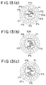
- the second stator teeth 25 of the salient pole 12 are just opposed to the mover teeth 26 in the circumferential direction, the second stator teeth 25 of the salient pole 14 are shifted from the mover teeth 26 by 2/5 of the tooth pitch ⁇ , the second stator teeth 25 of the salient pole 16 shifted by 4/5, the second stator teeth 25 of the salient pole 18 shifted by 6/5 or 1/5, and the second stator teeth 25 of the salient pole 20 shifted by 8/5 or 3/5. Accordingly, as shown in Fig.
- a rotary five-phase stepping motor having a basic step angle equal to 1/10 degree of the tooth pitch ⁇ , that is, 0.5 degree can be configured.
- the first stator teeth 24 having a tooth pitch in the shaft direction of m ⁇ t0 or 5t0 and a tooth thickness of the tooth tops 24a of 2t0 are formed in the stator salient poles 11, 13, 15, 17 and 19 in the shaft direction as shown in Fig. 11. Furthermore, the first stator teeth 24 of the salient pole 13 are shifted by 2/5 of the tooth pitch with respect to the salient pole 11, the teeth 24 of the salient pole 15 shifted by 4/5, the teeth 24 of the salient pole 17 shifted by 6/5 or 1/5, and the teeth 24 of the salient pole 19 shifted by 8/5 or 3/5.
- stator windings W1, W7, W3, W9 and W5 are set to A-, B-, C-, D- and E-phases, respectively, a linear five-phase stepping motor having a basic amount of movement of t0/2 can be configured.
- the combined linear-rotary five-phase stepping motor can be configured and each motor portion thereof can be controlled individually.
- stator iron core 10 can be formed as described below instead of lamination and rotation of the stator iron plates 30 by 144 degrees.
- Figs. 13(a) to 13(e) show examples of stator iron plates 30a, 30b, 30c, 30d and 30e having salient poles P1, P3, P5, P7 and P9 forming the first stator teeth 24 in the shaft direction of the stator iron core 10.
- Salient poles P2, P4, P6, P8 and P10 include second stator teeth 25 formed thereon in the circumferential direction.
- the stator iron plate 30a shown in Fig. 13(a) is punched by setting movable punches 5 and 9 pertinent to the salient poles P5 and P9 to a non-operating state and setting movable punches 1, 3, and 7 pertinent to other salient poles P1, P3 and P7 to an operating state so that the tooth tops 24a are formed at the tips of the salient poles P5 and P9 and the tooth bottoms 24b are formed at the tips of the salient poles P1, P3 and P7.
- the stator iron plate 30b shown in Fig. 13(b) is punched by setting the movable punches 1 and 5 pertinent to the salient poles P1 and P5 to the non-operating state and setting the movable punches 3, 7 and 9 pertinent to other salient poles P3, P7 and P9 to the operating state so that the tooth tops 24a are formed at the tips of the salient poles P1 and P5 and the tooth bottoms 24b are formed at the tips of the salient poles P3, P7 and P9.
- stator iron plates 30c, 30d and 30e shown in Figs. 13(c), 13(d) and 13(e) are punched by setting the movable punches 1, 3, ... 9 pertinent to the salient poles P1, P3, ... P9 to the non-operating state or the operating state selectively so that the predetermined tooth tops 24a or tooth bottoms 24b are formed at the tips of the salient poles P1, P3, ... P9.
- the punched stator iron plates 30a, 30b, 30c, 30d and 30e are laminated in the order of the description thereof, so that the first stator teeth 24 for one pitch can be formed at the tips of the salient poles P1, P3, ... P9.
- Figs. 14 to 16 illustrate a procedure of punching the stator iron plates 30a, 30b, 30c, 30d and 30e by a punching mold and laminating the punched stator iron plates successively in order to form the stator iron plate 10.
- Fig. 14 is a schematic diagram illustrating a portion for controlling movable punches of a punching mold.
- the movable punches 1, 3, 5, ... 9 included in the punching mold 31 and disposed to be able to be pushed out and withdrawn or be protruded and returned in each of the salient poles P1, P3, P5, ... P9 are controlled to be pushed out and withdrawn by driving solenoids selectively in the order of Fig. 15 by a punch controller 32 so that the tooth tops 24a or the tooth bottoms 24b of the first stator teeth 24 are formed at the tips of the salient poles P1, P2, P5, ... P9 of the stator iron plates 30 constituting the stator iron plate 10.
- numeral 32a denotes connecting leads.
- Fig. 15 is a diagram showing a relation of a punching and laminating order of the stator iron plates 30a, 30b, 30c, 30d and 30e and control states of the movable punches 1, 3, 5, ... 9.
- mark ⁇ represents the operating state of the punch (the punch is pushed out) for forming the tooth bottom 24b and mark ⁇ represents the non-operating state of the punch (the punch is withdrawn) for forming the tooth top 24a.
- Fig. 16 is a diagram for easily understanding control states of a movable punch 33 which is one of the movable punches 1, 3, 5, ... 9.
- Fig. 16(a) shows its operating state and
- Fig. 16(b) shows its non-operating state.
- the movable punch 33 is disposed in the punching mold 31 movably in the vertical direction and includes a cam 33a formed on an upper surface thereof and which abuts against a cam member 35 which is driven in the right direction in Fig. 16 by means of energization of the solenoid 34.
- the stator iron plate 10 can be formed by successively laminating the stator iron plate 30a, 30b, 30c, 30d and 30e punched as described above in the laminating order shown in Fig. 15.
- Fig. 17 shows an example of a stator iron plate 40 constituting the stator iron core 10 used in another example of the combined linear-rotary stepping motor of the embodiment.
- the salient poles P41, P42 and P45, P46 are paired, respectively, and include second stator teeth 25 formed in the circumferential direction.
- the salient poles P43, P44 and P47, P48 are paired, respectively, and include first stator teeth 24 formed in the shaft direction.
- An angle between center lines of the second stator teeth 25 formed in the salient poles P41 and P42 is 46.8 degrees and an angle between center lines of the second stator teeth 25 formed in the salient poles P42 and P45 is 131.4 degrees.
- an angle between center lines of the second stator teeth 25 formed in the salient poles P45 and P46 is 46.8 degrees.
- the number of mover teeth Zr disposed in the circumferential direction of the mover 2 or the second mover iron core 122c, 122d not shown is 50.
- the teeth 25 of the salient pole P41 are opposed to the mover teeth 26 of the mover 2 or the teeth 128 of the second mover iron core of the mover 102
- the teeth 25 of the salient pole P42 are shifted from the mover teeth 26 or the teeth 128 of the second mover iron core by 2/4 of the tooth pitch (7.2 degrees)
- stator windings wound on the salient poles P41 and P42 are connected so that the salient poles P41 and P42 have different polarities from each other when the stator windings wound on the salient poles P41 and P42 are energized, to thereby be able to constitute one phase.
- the teeth 25 of the salient pole P45 are shifted from the mover teeth 26 or the teeth 128 of the second mover iron core by 1/4 of the tooth pitch
- the teeth 25 of the salient poles P46 are shifted from the mover teeth 26 or the teeth 128 of the second mover iron core by 3/4 of the tooth pitch
- the teeth of the salient pole P45 is shifted from the teeth 25 of the salient pole P46 by 2/4 of the tooth pitch.
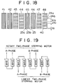
- Fig. 18 shows the first and second stator teeth 24 and 25 of the salient poles 41, 42, 43, ... 48 formed by punching and laminating the tips of the salient poles P43, P44, P47 and P48 of the stator iron plates 40 while the movable punches included in a punching mold in corresponding manner to the salient poles P43, P44, P47 and P48 are controlled to become the operating state as the punch or the non-operating state as the punch by the punch controller 32 so that the tips of the salient poles P43, P44, P47 and P48 constitute the tooth tops 24a or 24b periodically upon punching the stator iron plates 40 as viewed from the side of the mover 2.
- Hatched portions represent the tooth tops 24a and 25a and blank or unhatched portions represent the tooth bottoms 24b and 25b.
- the first stator teeth 24 having the tooth pitch of 2mt0 or 4t0 and the tooth thickness of 2t0 in the shaft direction are formed in the stator salient poles 43, 44, 47 and 48 in the shaft direction.
- the teeth 24 of the salient pole 44 are shifted from the salient pole 43 by 2/4 of the tooth pitch
- the teeth of the salient pole 47 is shifted from the salient pole 43 by 1/4 of the tooth pitch
- the teeth 24 of the salient pole 48 is shifted from the salient pole 43 by 3/4 of the tooth pitch. Accordingly, by connecting the stator windings W41, W42, W43, ... W48 as shown in Fig. 19, a hybrid type linear two-phase stepping motor having the basic amount of movement of t0 can be configured.
- the combined linear-rotary two-phase stepping motor can be configured.
- the magnetic circuits for each phase can be independent of each other and at the same time the magnetic circuits of the linear motor portion and the rotary motor portion can be independent of each other to reduce coupling between phase windings.
- the hybrid type stepping motor has been described, while the present invention can be applied to the variable reluctance type stepping motor similarly.
- the technique of the present invention is not limited to the technique of the embodiments and may be another means for performing the same function. Further, the technique of the present invention can be varied and added variously within the scope of the above configuration.
- the stator including the stator iron core having the plurality of salient poles of two kinds disposed radially inward, the salient poles of one kind having the plurality of first stator teeth formed in the inner peripheral surface thereof in the shaft direction and salient poles of the other kinds having the plurality of second stator teeth formed in the inner peripheral surface thereof in the circumferential direction, and the mover including the mover iron core supported within the stator movably in the shaft direction and rotatably in the rotation direction and having the plurality of mover teeth formed in the outer peripheral surface thereof at an equal pitch in the shaft direction and the circumferential direction in opposing relation to the first and second stator teeth.
- stator iron core is formed by rotating by the predetermined angle and laminating the stator iron plates or punching the iron plates forming the iron core by the punching mold while controlling to push out and withdraw the movable punches included in the punching mold and disposed to be able to be pushed out or withdrawn in each of the salient poles at the predetermined period for each punching of the iron plates and laminating the punched iron plates successively, the length in the shaft direction is not lengthened and the stator iron plates and the mover iron core for the linear motor portion and the rotary motor portion can be shared.
- stator iron core is formed by laminating the stator iron plates having the salient poles constituting the tooth tops and the salient poles constituting the tooth bottoms of the teeth, which are disposed in the predetermined relation, while rotating the stator iron plates by the predetermined angle determined by the number of phases, the number of salient poles and the predetermined relation so that the first stator teeth are formed in the inner peripheral surfaces of the salient poles in the shaft direction and at the same time the second stator teeth are laminated while rotated by the predetermined angle to thereby laminate the tooth tops and the tooth bottoms, the stator iron plates and the mover iron core can be shared and the ratio of the mover for the linear motor portion and the rotary motor can be set to any value.
- stator iron core can be formed by punching the iron plates constituting the iron core by the punching mold while controlling to selectively push out and withdraw the movable punches included within the punching mold and disposed to be able to be pushed out and withdrawn in each of the salient poles so that the tips of the salient poles constitute the tooth tops or the tooth bottoms of the first stator teeth at the predetermined period for each punching of the iron plate and laminating the punched iron plates successively in order to form the first stator teeth in the inner peripheral surface of the salient pole in the shaft direction, the stator iron plates and the mover iron core can be shared and the ratio of the mover for the linear motor portion and the rotary motor portion can be set to any value.
- the manufacturing method of the stator iron core is described and the stator iron plates of cm kinds can be laminated successively repeatedly to thereby form the first stator teeth of the linear motor portion.
- the manufacturing method of the stator iron plates of cm kinds is not limited specifically and iron plates punched by different punching molds may be laminated successively.
Landscapes
- Engineering & Computer Science (AREA)
- Power Engineering (AREA)
- Physics & Mathematics (AREA)
- Chemical & Material Sciences (AREA)
- Combustion & Propulsion (AREA)
- Electromagnetism (AREA)
- Linear Motors (AREA)
Applications Claiming Priority (4)
| Application Number | Priority Date | Filing Date | Title |
|---|---|---|---|
| JP290176/93 | 1993-11-19 | ||
| JP29017693A JP3393902B2 (ja) | 1993-11-19 | 1993-11-19 | リニア・ロータリ複合型ステッピングモータ |
| JP19808294A JP3432295B2 (ja) | 1994-08-23 | 1994-08-23 | リニア・ロータリ複合型ステッピングモータ |
| JP198082/94 | 1994-08-23 |
Publications (2)
| Publication Number | Publication Date |
|---|---|
| EP0655825A1 true EP0655825A1 (fr) | 1995-05-31 |
| EP0655825B1 EP0655825B1 (fr) | 1997-06-04 |
Family
ID=26510761
Family Applications (1)
| Application Number | Title | Priority Date | Filing Date |
|---|---|---|---|
| EP94118156A Expired - Lifetime EP0655825B1 (fr) | 1993-11-19 | 1994-11-17 | Moteur pas à pas combiné linéaire et rotatif |
Country Status (6)
| Country | Link |
|---|---|
| US (1) | US5627418A (fr) |
| EP (1) | EP0655825B1 (fr) |
| KR (1) | KR0144109B1 (fr) |
| CN (1) | CN1108015A (fr) |
| CA (1) | CA2135817C (fr) |
| DE (1) | DE69403613T2 (fr) |
Cited By (8)
| Publication number | Priority date | Publication date | Assignee | Title |
|---|---|---|---|---|
| WO1997046338A1 (fr) * | 1996-06-05 | 1997-12-11 | L.H. Carbide Corporation | Pile en stratifie ayant au moins une couche dotee d'une pluralite de segments discrets, dispositif et procede pour la fabrication |
| US5799387A (en) * | 1996-06-05 | 1998-09-01 | L.H. Carbide Corpordation | Lamina stack having a plurality of outer perimeter configurations and an apparatus and method for manufacturing said stack |
| US6163949A (en) * | 1996-06-05 | 2000-12-26 | L.H. Carbide Corporation | Method for manufacturing long, slender lamina stack from nonuniform laminae |
| US6195875B1 (en) | 1996-06-05 | 2001-03-06 | L.H. Carbide Corporation | Apparatus for manufacturing long, slender lamina stacks from nonuniform laminae |
| US6636137B1 (en) | 1996-06-05 | 2003-10-21 | L.H. Carbide Corporation | Ignition coil assembly |
| DE102005019112A1 (de) * | 2005-04-25 | 2006-10-26 | Siemens Ag | Kombinationsantrieb mit Hybridreluktanzmotor |
| WO2007057412A1 (fr) * | 2005-11-21 | 2007-05-24 | Robert Bosch Gmbh | Arrangement de tôles de rotor d’une machine électrique à excitation permanente |
| FR2969853A1 (fr) * | 2010-12-22 | 2012-06-29 | Fed Mogul Sintertech | Machine homopolaire ayant des epaisseurs de dent variables, mesurees radialement dans un plan axial. |
Families Citing this family (33)
| Publication number | Priority date | Publication date | Assignee | Title |
|---|---|---|---|---|
| US5661446A (en) * | 1995-06-07 | 1997-08-26 | Mts Systems Corporation | Electromagnetic actuator |
| DE19958888A1 (de) * | 1999-12-07 | 2001-06-13 | Sheng Chih Sheng | Magnetvorrichtung mit wechselbarem Magnetkreis und mit beiden Befestigungsstellen |
| KR100346275B1 (ko) * | 1999-12-15 | 2002-07-26 | 엘지전자주식회사 | 로터리 리니어 전동기 |
| US6429611B1 (en) | 2000-01-28 | 2002-08-06 | Hui Li | Rotary and linear motor |
| KR100360259B1 (ko) * | 2000-07-26 | 2002-11-09 | 엘지전자 주식회사 | 2자유도형 전동기 |
| AU2002211680A1 (en) | 2000-10-13 | 2002-04-22 | Clarity, L.L.C. | Magnetic actuation and positioning |
| JP2003018773A (ja) * | 2001-06-28 | 2003-01-17 | Sankyo Seiki Mfg Co Ltd | コア付きモータ |
| US6879082B2 (en) * | 2002-03-25 | 2005-04-12 | Clarity Technologies, Inc. | Electromagnetic positioning |
| US20040155545A1 (en) * | 2003-02-06 | 2004-08-12 | Martin Kaplan | Switched reluctance motor having improved stator pole design |
| US20050275303A1 (en) * | 2004-06-09 | 2005-12-15 | Tetmeyer Michael E | Differential flux permanent magnet machine |
| DE102004048105A1 (de) * | 2004-10-02 | 2006-04-06 | Bosch Rexroth Aktiengesellschaft | Stator einer elektrischen Maschine |
| US7752733B1 (en) * | 2006-11-06 | 2010-07-13 | Lin Engineering, Inc. | Laser welded step motor construction with compact end cap and stator lamination positioning |
| US7898120B2 (en) * | 2007-05-31 | 2011-03-01 | The Boeing Company | Linear-rotary actuators and actuator systems |
| JPWO2010010599A1 (ja) | 2008-07-24 | 2012-01-05 | 三菱電機株式会社 | 鉄心の製造方法及び鉄心の製造装置 |
| JP5655071B2 (ja) * | 2010-06-08 | 2015-01-14 | 株式会社日立製作所 | リニアモータ |
| CN102315751A (zh) * | 2010-07-05 | 2012-01-11 | 上海鸣志电器有限公司 | 一种加强型步进电机 |
| GB2487227A (en) | 2011-01-14 | 2012-07-18 | Mechadyne Plc | Spool valve for simultaneous control of two output members |
| CN102684450B (zh) * | 2012-06-18 | 2014-08-20 | 上海理工大学 | 直线旋转磁阻步进电机转子结构 |
| CN102710095A (zh) * | 2012-06-26 | 2012-10-03 | 上海理工大学 | 一种微距高稳定性直线旋转磁阻步进电机转子 |
| DE102012224177A1 (de) | 2012-12-21 | 2014-06-26 | Olympus Winter & Ibe Gmbh | Elektromagnetischer Aktuator für ein chirurgisches Instrument und Verfahren zum Einstellen eines Hubwegs |
| CN111765664B (zh) * | 2013-08-02 | 2022-04-05 | 查特股份有限公司 | 具有磁性往复运动活塞的低温制冷机 |
| CN104019266B (zh) * | 2014-06-23 | 2016-04-20 | 哈尔滨工业大学 | 双稳态直动式含永磁电磁阀 |
| DE102014111239B4 (de) * | 2014-08-07 | 2016-07-21 | Schuler Pressen Gmbh | Blechpaket eines Stators oder eines Läufers sowie eine elektrische Maschine |
| CN105375713B (zh) * | 2014-08-29 | 2018-02-16 | 香港理工大学 | 双轴电机及双轴驱动方法 |
| KR20170015747A (ko) | 2015-07-31 | 2017-02-09 | 주식회사 아이블라인드 | 블라인드 제어 시스템 |
| WO2018083898A1 (fr) * | 2016-11-01 | 2018-05-11 | 三菱電機株式会社 | Moteur |
| EP3827507A1 (fr) * | 2018-07-24 | 2021-06-02 | Mainspring Energy, Inc. | Machine électromagnétique linéaire |
| CN108894999B (zh) * | 2018-08-13 | 2024-08-27 | 佰顿新材料科技(江苏)有限公司 | 电动水泵 |
| EP3672040A1 (fr) * | 2018-12-17 | 2020-06-24 | Nexperia B.V. | Dispositif permettant un mouvement de rotation et de translation à l'aide d'un seul moteur ; appareil et système comprenant un tel dispositif |
| CN109639091B (zh) * | 2019-01-11 | 2024-11-15 | 黄石东贝压缩机有限公司 | 直线电机及压缩机 |
| DE102019217527A1 (de) * | 2019-11-13 | 2021-05-20 | Fertigungsgerätebau Adolf Steinbach GmbH & Co. KG | Antriebseinheit zur Erzeugung einer translatorischen Bewegung |
| CN115912694B (zh) * | 2022-11-25 | 2025-12-12 | 上海鸣志电器股份有限公司 | 一种步进电机定子及具有该定子的步进电机 |
| CN120855797B (zh) * | 2025-09-22 | 2025-12-05 | 山东大学 | 旋转直线运动末端执行器驱动装置及驱动、参数调整方法 |
Citations (5)
| Publication number | Priority date | Publication date | Assignee | Title |
|---|---|---|---|---|
| US3889165A (en) * | 1971-09-28 | 1975-06-10 | Telemecanique Electrique | Linear and rotary actuator |
| EP0004995A1 (fr) * | 1978-04-17 | 1979-10-31 | IMC Magnetics Corporation | Dispositif linéaire et rotatif |
| US4719381A (en) * | 1985-08-21 | 1988-01-12 | The Curators Of The University Of Missouri | Electrical machines and apparatus for rotation around multiple axes |
| EP0319096A2 (fr) * | 1987-12-02 | 1989-06-07 | Koninklijke Philips Electronics N.V. | Moteur linéaire ayant des pôles magnétiques cranterant angulairement |
| US5093596A (en) * | 1990-10-24 | 1992-03-03 | Ibm Corporation | Combined linear-rotary direct drive step motor |
Family Cites Families (2)
| Publication number | Priority date | Publication date | Assignee | Title |
|---|---|---|---|---|
| US4618808A (en) * | 1985-01-30 | 1986-10-21 | International Business Machines Corporation | Electromagnetic actuator system using stepper motor with closed loop position sensing, electronic commutation and dynamic position and anomaly correction |
| US4712027A (en) * | 1986-03-21 | 1987-12-08 | International Business Machines Corporation | Radial pole linear reluctance motor |
-
1994
- 1994-11-15 CA CA002135817A patent/CA2135817C/fr not_active Expired - Fee Related
- 1994-11-17 EP EP94118156A patent/EP0655825B1/fr not_active Expired - Lifetime
- 1994-11-17 US US08/341,099 patent/US5627418A/en not_active Expired - Fee Related
- 1994-11-17 DE DE69403613T patent/DE69403613T2/de not_active Expired - Fee Related
- 1994-11-18 CN CN94118922A patent/CN1108015A/zh active Pending
- 1994-11-18 KR KR1019940030398A patent/KR0144109B1/ko not_active Expired - Fee Related
Patent Citations (5)
| Publication number | Priority date | Publication date | Assignee | Title |
|---|---|---|---|---|
| US3889165A (en) * | 1971-09-28 | 1975-06-10 | Telemecanique Electrique | Linear and rotary actuator |
| EP0004995A1 (fr) * | 1978-04-17 | 1979-10-31 | IMC Magnetics Corporation | Dispositif linéaire et rotatif |
| US4719381A (en) * | 1985-08-21 | 1988-01-12 | The Curators Of The University Of Missouri | Electrical machines and apparatus for rotation around multiple axes |
| EP0319096A2 (fr) * | 1987-12-02 | 1989-06-07 | Koninklijke Philips Electronics N.V. | Moteur linéaire ayant des pôles magnétiques cranterant angulairement |
| US5093596A (en) * | 1990-10-24 | 1992-03-03 | Ibm Corporation | Combined linear-rotary direct drive step motor |
Cited By (13)
| Publication number | Priority date | Publication date | Assignee | Title |
|---|---|---|---|---|
| US6636137B1 (en) | 1996-06-05 | 2003-10-21 | L.H. Carbide Corporation | Ignition coil assembly |
| US5799387A (en) * | 1996-06-05 | 1998-09-01 | L.H. Carbide Corpordation | Lamina stack having a plurality of outer perimeter configurations and an apparatus and method for manufacturing said stack |
| US6000119A (en) * | 1996-06-05 | 1999-12-14 | L.H. Carbide Corporation | Lamina stack having a plurality of outer perimeter configurations and an apparatus and method for manufacturing said stack |
| US6131268A (en) * | 1996-06-05 | 2000-10-17 | L. H. Carbide Corporation | Method for manufacturing a lamina stack having at least two differently shaped lamina layers |
| US6163949A (en) * | 1996-06-05 | 2000-12-26 | L.H. Carbide Corporation | Method for manufacturing long, slender lamina stack from nonuniform laminae |
| US6195875B1 (en) | 1996-06-05 | 2001-03-06 | L.H. Carbide Corporation | Apparatus for manufacturing long, slender lamina stacks from nonuniform laminae |
| WO1997046338A1 (fr) * | 1996-06-05 | 1997-12-11 | L.H. Carbide Corporation | Pile en stratifie ayant au moins une couche dotee d'une pluralite de segments discrets, dispositif et procede pour la fabrication |
| US6745458B2 (en) | 1996-06-05 | 2004-06-08 | L.H. Carbide Corporation | Laminated magnetic core and method for making |
| DE102005019112A1 (de) * | 2005-04-25 | 2006-10-26 | Siemens Ag | Kombinationsantrieb mit Hybridreluktanzmotor |
| WO2006114390A1 (fr) * | 2005-04-25 | 2006-11-02 | Siemens Aktiengesellschaft | Mecanisme d'entrainement combine dote d'un moteur a reluctance hybride |
| US8063517B2 (en) | 2005-04-25 | 2011-11-22 | Siemens Aktiengesellschaft | Combination drive with a hybrid reluctance motor |
| WO2007057412A1 (fr) * | 2005-11-21 | 2007-05-24 | Robert Bosch Gmbh | Arrangement de tôles de rotor d’une machine électrique à excitation permanente |
| FR2969853A1 (fr) * | 2010-12-22 | 2012-06-29 | Fed Mogul Sintertech | Machine homopolaire ayant des epaisseurs de dent variables, mesurees radialement dans un plan axial. |
Also Published As
| Publication number | Publication date |
|---|---|
| CA2135817A1 (fr) | 1995-05-20 |
| KR950015919A (ko) | 1995-06-17 |
| DE69403613T2 (de) | 1998-01-02 |
| EP0655825B1 (fr) | 1997-06-04 |
| DE69403613D1 (de) | 1997-07-10 |
| US5627418A (en) | 1997-05-06 |
| KR0144109B1 (ko) | 1998-10-01 |
| CA2135817C (fr) | 1998-08-11 |
| CN1108015A (zh) | 1995-09-06 |
Similar Documents
| Publication | Publication Date | Title |
|---|---|---|
| EP0655825B1 (fr) | Moteur pas à pas combiné linéaire et rotatif | |
| US5218250A (en) | Strong magnetic thrust force type actuator | |
| EP0643470A1 (fr) | Moteur linéaire | |
| US4794286A (en) | Variable reluctance stepper motor | |
| EP0645877B1 (fr) | Moteur linéaire | |
| EP0622887B1 (fr) | Moteur linéaire pas à pas | |
| EP0645876B1 (fr) | Moteur linéaire pas à pas | |
| EP0650247B1 (fr) | Procédé de fabrication d'un noyau en fer pour moteur linéaire multiphasé | |
| EP2324563B1 (fr) | Moteurs pas à pas à aimant permanent | |
| US5418413A (en) | Linear pulse motor | |
| JP3393902B2 (ja) | リニア・ロータリ複合型ステッピングモータ | |
| JP3432295B2 (ja) | リニア・ロータリ複合型ステッピングモータ | |
| JPH08163857A (ja) | 回転形リニアパルスモータ | |
| JP3369317B2 (ja) | 多相リニアモータの鉄心製造方法 | |
| JP3207302B2 (ja) | リニアパルスモータ | |
| JP3207301B2 (ja) | リニアパルスモータ | |
| JPH0739135A (ja) | 円筒形リニアパルスモータ | |
| JPH07170717A (ja) | 円筒形リニアパルスモータ | |
| JPS6225867A (ja) | リニアステツピングモ−タ |
Legal Events
| Date | Code | Title | Description |
|---|---|---|---|
| PUAI | Public reference made under article 153(3) epc to a published international application that has entered the european phase |
Free format text: ORIGINAL CODE: 0009012 |
|
| AK | Designated contracting states |
Kind code of ref document: A1 Designated state(s): CH DE FR GB IT LI NL |
|
| 17P | Request for examination filed |
Effective date: 19950707 |
|
| 17Q | First examination report despatched |
Effective date: 19960213 |
|
| GRAG | Despatch of communication of intention to grant |
Free format text: ORIGINAL CODE: EPIDOS AGRA |
|
| GRAH | Despatch of communication of intention to grant a patent |
Free format text: ORIGINAL CODE: EPIDOS IGRA |
|
| GRAH | Despatch of communication of intention to grant a patent |
Free format text: ORIGINAL CODE: EPIDOS IGRA |
|
| GRAA | (expected) grant |
Free format text: ORIGINAL CODE: 0009210 |
|
| ITF | It: translation for a ep patent filed | ||
| AK | Designated contracting states |
Kind code of ref document: B1 Designated state(s): CH DE FR GB IT LI NL |
|
| REG | Reference to a national code |
Ref country code: CH Ref legal event code: EP |
|
| REF | Corresponds to: |
Ref document number: 69403613 Country of ref document: DE Date of ref document: 19970710 |
|
| REG | Reference to a national code |
Ref country code: CH Ref legal event code: NV Representative=s name: PATENTANWAELTE SCHAAD, BALASS, MENZL & PARTNER AG |
|
| ET | Fr: translation filed | ||
| PLBE | No opposition filed within time limit |
Free format text: ORIGINAL CODE: 0009261 |
|
| STAA | Information on the status of an ep patent application or granted ep patent |
Free format text: STATUS: NO OPPOSITION FILED WITHIN TIME LIMIT |
|
| 26N | No opposition filed | ||
| PGFP | Annual fee paid to national office [announced via postgrant information from national office to epo] |
Ref country code: FR Payment date: 19981027 Year of fee payment: 5 Ref country code: CH Payment date: 19981027 Year of fee payment: 5 |
|
| PGFP | Annual fee paid to national office [announced via postgrant information from national office to epo] |
Ref country code: GB Payment date: 19981030 Year of fee payment: 5 |
|
| PGFP | Annual fee paid to national office [announced via postgrant information from national office to epo] |
Ref country code: NL Payment date: 19981125 Year of fee payment: 5 |
|
| PG25 | Lapsed in a contracting state [announced via postgrant information from national office to epo] |
Ref country code: GB Free format text: LAPSE BECAUSE OF NON-PAYMENT OF DUE FEES Effective date: 19991117 |
|
| PG25 | Lapsed in a contracting state [announced via postgrant information from national office to epo] |
Ref country code: LI Free format text: LAPSE BECAUSE OF NON-PAYMENT OF DUE FEES Effective date: 19991130 Ref country code: CH Free format text: LAPSE BECAUSE OF NON-PAYMENT OF DUE FEES Effective date: 19991130 |
|
| PG25 | Lapsed in a contracting state [announced via postgrant information from national office to epo] |
Ref country code: NL Free format text: LAPSE BECAUSE OF NON-PAYMENT OF DUE FEES Effective date: 20000601 |
|
| GBPC | Gb: european patent ceased through non-payment of renewal fee |
Effective date: 19991117 |
|
| REG | Reference to a national code |
Ref country code: CH Ref legal event code: PL |
|
| PG25 | Lapsed in a contracting state [announced via postgrant information from national office to epo] |
Ref country code: FR Free format text: LAPSE BECAUSE OF NON-PAYMENT OF DUE FEES Effective date: 20000731 |
|
| NLV4 | Nl: lapsed or anulled due to non-payment of the annual fee |
Effective date: 20000601 |
|
| REG | Reference to a national code |
Ref country code: FR Ref legal event code: ST |
|
| PG25 | Lapsed in a contracting state [announced via postgrant information from national office to epo] |
Ref country code: IT Free format text: LAPSE BECAUSE OF NON-PAYMENT OF DUE FEES;WARNING: LAPSES OF ITALIAN PATENTS WITH EFFECTIVE DATE BEFORE 2007 MAY HAVE OCCURRED AT ANY TIME BEFORE 2007. THE CORRECT EFFECTIVE DATE MAY BE DIFFERENT FROM THE ONE RECORDED. Effective date: 20051117 |
|
| PGFP | Annual fee paid to national office [announced via postgrant information from national office to epo] |
Ref country code: DE Payment date: 20071126 Year of fee payment: 14 |
|
| PG25 | Lapsed in a contracting state [announced via postgrant information from national office to epo] |
Ref country code: DE Free format text: LAPSE BECAUSE OF NON-PAYMENT OF DUE FEES Effective date: 20090603 |