EP0656719A1 - Dispositif de commande à distance et appareil d'entrée d'image - Google Patents
Dispositif de commande à distance et appareil d'entrée d'image Download PDFInfo
- Publication number
- EP0656719A1 EP0656719A1 EP94119000A EP94119000A EP0656719A1 EP 0656719 A1 EP0656719 A1 EP 0656719A1 EP 94119000 A EP94119000 A EP 94119000A EP 94119000 A EP94119000 A EP 94119000A EP 0656719 A1 EP0656719 A1 EP 0656719A1
- Authority
- EP
- European Patent Office
- Prior art keywords
- remote
- control
- controlled
- image input
- control signal
- Prior art date
- Legal status (The legal status is an assumption and is not a legal conclusion. Google has not performed a legal analysis and makes no representation as to the accuracy of the status listed.)
- Granted
Links
- 238000004891 communication Methods 0.000 claims description 41
- 238000006243 chemical reaction Methods 0.000 claims description 18
- 230000008859 change Effects 0.000 claims description 7
- 230000005540 biological transmission Effects 0.000 claims description 6
- 238000000034 method Methods 0.000 description 6
- 238000012545 processing Methods 0.000 description 6
- 238000010276 construction Methods 0.000 description 4
- 238000010586 diagram Methods 0.000 description 4
- 238000001914 filtration Methods 0.000 description 3
- 238000012544 monitoring process Methods 0.000 description 3
- 230000008901 benefit Effects 0.000 description 2
- 230000007246 mechanism Effects 0.000 description 2
- 238000012986 modification Methods 0.000 description 2
- 230000004048 modification Effects 0.000 description 2
- 230000005855 radiation Effects 0.000 description 2
- 230000008054 signal transmission Effects 0.000 description 2
- 230000010485 coping Effects 0.000 description 1
- 238000001514 detection method Methods 0.000 description 1
- 230000009977 dual effect Effects 0.000 description 1
- 238000004091 panning Methods 0.000 description 1
- 230000004044 response Effects 0.000 description 1
Images


Classifications
-
- H—ELECTRICITY
- H04—ELECTRIC COMMUNICATION TECHNIQUE
- H04M—TELEPHONIC COMMUNICATION
- H04M11/00—Telephonic communication systems specially adapted for combination with other electrical systems
- H04M11/007—Telephonic communication systems specially adapted for combination with other electrical systems with remote control systems
-
- G—PHYSICS
- G08—SIGNALLING
- G08C—TRANSMISSION SYSTEMS FOR MEASURED VALUES, CONTROL OR SIMILAR SIGNALS
- G08C25/00—Arrangements for preventing or correcting errors; Monitoring arrangements
- G08C25/02—Arrangements for preventing or correcting errors; Monitoring arrangements by signalling back receiving station to transmitting station
-
- H—ELECTRICITY
- H04—ELECTRIC COMMUNICATION TECHNIQUE
- H04N—PICTORIAL COMMUNICATION, e.g. TELEVISION
- H04N7/00—Television systems
- H04N7/18—Closed-circuit television [CCTV] systems, i.e. systems in which the video signal is not broadcast
- H04N7/183—Closed-circuit television [CCTV] systems, i.e. systems in which the video signal is not broadcast for receiving images from a single remote source
- H04N7/185—Closed-circuit television [CCTV] systems, i.e. systems in which the video signal is not broadcast for receiving images from a single remote source from a mobile camera, e.g. for remote control
Definitions
- the present invention relates to a remote-control apparatus for remotely controlling controlled apparatuses, such as electrical apparatuses, and an image input apparatus.
- Remote-control systems which remotely control electrical apparatuses, such as in-house electrical apparatuses, through communication lines such as telephone lines, are known.
- a wireless communication line (employing, for example, electromagnetic waves, or infrared rays) is disposed between a telephone set, specifically an automatic answering telephone set, and a controlled apparatus.
- a predetermined control signal (for example, a control signal in accordance with DTMF (Dual Tone Multi Frequency)) is transmitted to the telephone set from an outside place where the user is located, and a wireless control signal corresponding to the control signal received by the telephone set is transmitted to the controlled apparatus.
- DTMF Dual Tone Multi Frequency
- a wired connection arrangement called a home bus rather than wireless connection is known.
- a wiring work must be done beforehand, and there is also a drawback in that it is difficult to cope with the change in the position of the controlled apparatus and the expansion thereof.
- the wireless method has no wiring requirement and has the advantage of being capable of flexibly coping with the change in the position of the controlled apparatus and the expansion thereof.
- infrared rays or microwaves are usually used at a relatively sharp directivity. This, however, causes an inconvenience in that the position at which a controlled apparatus or a telephone set is installed is limited. Further, when a plurality of controlled apparatuses are to be controlled, the receivers of the respective controlled apparatuses must be disposed on the same line.
- the present invention aims to solve the above-described problems of the prior art. It is an object of the present invention to provide an apparatus capable of monitoring one or more controlled apparatuses from a remote place in the form of a video image and which is capable of easily confirming the operation of the controlled apparatus before and after the remote operation at a remote place.
- a remote-control apparatus for remotely controlling one or more controlled apparatuses, comprising image input means for inputting an image of a controlled apparatus, control means for controlling the controlled apparatus the image of which has been input by the image input means, and image transmitting means for outputting the image input by the image input means to outside the remote-control apparatus.
- a remote-control apparatus for remotely controlling one or more controlled apparatuses by using a wireless signal, comprising transmitting means for transmitting a control signal to a controlled apparatus, transmission destination control means for controlling the direction of the control signal transmitted by the transmitting means, and control signal receiving means for receiving a control signal for the transmission destination control means through a communication line.
- a remote-control apparatus for remotely controlling one or more controlled apparatuses by using a wireless signal, comprising image input means for inputting an image of a controlled apparatus, image transmitting means for outputting the image input by the image input means to outside the remote-control apparatus, drive control means for driving and controlling the image input means, first receiving means for receiving a first control signal for the drive control means from outside the remote-control apparatus, second receiving means for receiving a second control signal for instructing a remote operation for the one or more controlled apparatuses from outside the remote-control apparatus, conversion means for converting the second control signal received by the second receiving means into a remote-control signal for the one or more controlled apparatuses, and output means for outputting the remote control signal converted by the conversion means in the form of a wireless signal.
- an image input apparatus comprising image input means for inputting an image of an object, control means for controlling one or more controlled apparatuses by using a wireless signal, and image transmitting means for outputting the image input by the image input means to outside the image input apparatus.
- a remote-control apparatus for remotely controlling one or more controlled apparatuses by using a wireless signal, comprising orientation storing means for storing the orientation of each of the one or more controlled apparatuses, control signal output means for outputting a control signal for a controlled apparatus in the form of a wireless signal, and orientation change means for changing the orientation of an output of the control signal output means to the orientation of the controlled apparatus to be controlled, by referring to the orientation storing means in accordance with the selection of the controlled apparatus to be controlled.
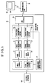
- Fig. 1 shows a block diagram of the schematic construction of a first embodiment of the present invention.
- reference numeral 10 denotes a remote-control apparatus of the first embodiment of the present invention
- reference numeral 12 denotes a video camera which, in addition to being used as a video telephone set to take an image of a user, is used as a monitor camera during a remote operation
- reference numeral 14 denotes a video interface for converting video signals output from the video camera 12 into a predetermined internal format
- reference numeral 16 denotes a video processing circuit for performing filtering and encoding on the output of the video interface 14.
- Reference numeral 18 denotes a line control circuit for controlling communications over a communication line, which circuit comprises a video signal transmitting section 18a for transmitting the output from the video processing circuit 16 and a control signal receiving section 18b for receiving various control signals, such as DTMF, from the communication line.
- the line control circuit 18 is connected to a communication line 30 via a line interface 20.
- Reference numeral 22 denotes a signal conversion circuit for converting the output of the control signal receiving section 18b into the signal format of a remote control signal for a specific electrical apparatus to be controlled
- reference numeral 24 denotes a drive circuit for driving a light emitting element 26 in accordance with the output from the signal conversion circuit 22.
- the light emitting element 26 outputs an infrared wireless control signal when the light emitting element 26 is driven by the drive circuit 24.
- infrared ray microwaves, radio waves or ultrasonic waves may be used.
- infrared rays are commonly used to remotely control in-house electrical apparatuses, and the degree of use is high.
- the light emitting element 26 is formed integrally with the video camera 12, and always directs the same orientation as that of the video camera 12.
- Reference numeral 28 denotes a camera drive control circuit for controlling the orientation, focus and zoom of the video camera 12 in accordance with the camera control signal received over the communication line 30.
- the camera control signal is separated from the received signal by the control signal receiving section 18b and supplied to the camera drive control circuit 28.
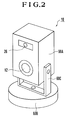
- Fig. 2 is a perspective view of the exterior of the remote-control apparatus 10, particularly, the portion in which the video camera 12 and the light emitting element 26 are formed as one unit.
- a body case 60A In a body case 60A, the video camera 12 and the light emitting element 26 are disposed. Also, the body case 60A is tiltably supported by a supporting member 60C so that the body case 60A can be tilted relative to a mount 60B, and a tilting drive mechanism is housed inside the body case 60A. A panning drive mechanism is housed in the mount 60B so that the body case 60A can be panned via the supporting member 60C.
- Fig. 3 is a flowchart illustrating the operation thereof.
- the user originates a call from a video telephone set 32 at the outside place where the user is located to the in-house remote-control apparatus 10 (S1) via the communication line 30.
- the remote-control apparatus 10 inside the user's house responds to this call, and a mutual communication is established.
- An image taken by the video camera 12 of the remote-control apparatus 10 is displayed on a monitor screen 32a of the video telephone set 32 at the outside place where the user is located.
- the video camera 12 is remotely controlled while the user is watching the displayed image (S2).
- the video signal output from the video camera 12 is converted in a format by the video interface 14, after which a filtering and an encoding operation are performed on the signal by the video processing circuit 16.
- the video signal transmitting section 18a outputs the output of the video processing circuit 16 to the communication line 30 via the line interface 20.
- the situation inside the user's house is displayed on the monitor screen 32a of the video telephone set 32 at the outside place where the user is located.
- a control signal such as DTMF, for driving and controlling the video camera 12, i.e., a camera control signal
- a camera control signal is transmitted from the video telephone set 32 at the outside place where the user is located to the remote-control apparatus 10 via the communication line 30 while the user is watching the monitor screen 32a.
- This camera control signal is supplied to the camera drive control circuit 28 via the line interface 20 and the control signal receiving section 18b.
- the camera drive control circuit 28 controls the orientation, zoom and focus of the video camera 12. Since the light emitting element 26 is formed integrally with the video camera 12, the camera drive control circuit 28 also controls the orientation of the light emitting element 26.
- an in-house electrical apparatus 100 to be remotely controlled is displayed on the video telephone set 32 at the outside place where the user is located (S3), the desired in-house electrical apparatus 100 is remotely controlled.
- a remote control signal for the in-house electrical apparatus 100 to be controlled is transmitted to the remote-control apparatus 10 via the communication line 30 from the video telephone set 32 at the outside place where the user is located (S4).
- the remote control signal is supplied to the control signal receiving section 18b via the line interface 20.
- the signal conversion circuit 22 converts the remote control signal which is input from the control signal receiving section 18b into a control signal for the in-house electrical apparatus 100 to be controlled, and the control signal is applied to the light emitting element 26 via the drive circuit 24.
- the light emitting element 26 emanates an infrared control signal toward the in-house electrical apparatus 100 to be controlled.
- the first embodiment in addition to the arrangement of the dedicated apparatus for remote control, can be realized by various apparatus arrangements, such as an automatic answering video telephone set or an automatic answering telephone set having a video camera. Also, the first embodiment can be realized by adding a remote control function to an image input apparatus.
- PSTN public switched telephone network
- ISDN ISDN
- LAN local area network
- the video processing circuit 16 for performing filtering or encoding on video signals is disposed, the video processing circuit 16 is not an indispensable component of the present invention.
- the control signal receiving section 18b receives both the camera control signal and the control signal for remotely controlling a controlled apparatus, control signal receiving sections for receiving the respective signals separately may be disposed.
- the video camera 12 and the light emitting element 26 are formed as one unit in the first embodiment, they may be driven and controlled separately.
- the camera drive control signal and the control signal for instructing a remote operation of the controlled apparatus are not limited to DTMF, but other formats, such as ISDN user-to-user information, may be used.
- the signal transmission medium through which the signals are transmitted from the remote-control apparatus 10 to the in-house electrical apparatus 100 in the first embodiment is not limited to an infrared ray, but visible light, an electromagnetic wave or an ultrasonic wave may be used.
- the electrical apparatuses which are remotely controlled include various apparatuses such as OA apparatuses.
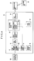
- FIG. 4 is a block diagram illustrating the schematic construction of the second embodiment of the present invention.
- reference numeral 40 denotes a remote-control apparatus of the second embodiment
- reference numeral 42 denotes a light emitting element for transmitting an infrared control signal to the electrical apparatus 100 which is a controlled apparatus
- reference numeral 44 denotes a scanning circuit 44 for rotationally scanning the light emitting element 42 and changing the radiation direction of its output light
- reference numeral 46 denotes a storage circuit for storing the orientation of each electrical apparatus together with the identifier of the electrical apparatus.
- Reference numeral 48 denotes a line interface through which a connection is made with the communication line
- reference numeral 50 denotes a line control circuit for controlling communications over the communication line 30, which circuit comprises a control signal receiving section 50a for receiving various control signals, such as DTMF, from the communication line
- reference numeral 52 denotes a signal conversion circuit for converting control signals from the communication line 30, specifically, control signals output from the control signal receiving section 50a, into a control signal format for the electrical apparatus 100 to be controlled
- reference numeral 54 denotes a drive circuit for driving the light emitting element 42 in accordance with the output from the signal conversion circuit 52.
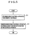
- Fig. 5 is a flowchart of the operation in which the user registers the orientation of one or more in-house electrical apparatuses (controlled apparatuses) 100 or the remote-control apparatus 40.
- a scanning device 42a scans the radiation direction of the light emitting element 42 and sets the orientation of the in-house electrical apparatus to be controlled (S11).
- the user manually instructs the orientation of the electrical apparatus 100 to be remotely controlled via an input device 58 of the remote-control apparatus 40, and the scanning device 42a directs the light emitting element 42 toward the instructed orientation.
- the user himself determines if the orientation is appropriate or not.
- the determined orientation of the in-house electrical apparatus 100 to be controlled is registered in the storage circuit 46 together with the identifier of the in-house electrical apparatus 100 (S12).
- the identifier of the in-house electrical apparatus 100 may be mere consecutive numerals input, for example, via the input device 58.
- Fig. 6 is a flowchart of a case in which an in-house electrical apparatus is remotely controlled from an outside place where the user is located.
- the user originates a call to the remote-control apparatus 40 inside the user's house from a telephone set 56 at the outside place where the user is located (S21).
- the remote-control apparatus 40 responds to this call, the user selects the in-house electrical apparatus 100 to be remotely controlled from the telephone set 56 at the outside place where the user is located (S22), and the remote-control apparatus 40, in response to this selection, directs the light emitting element 42 toward the selected in-house electrical apparatus 100 (S23).
- a control signal such as DTMF, indicating the identifier of the in-house electrical apparatus 100 to be remotely controlled, is transmitted over the communication line 30 from the telephone set 56 at the outside place where the user is located.
- the control signal is applied to the scanning circuit 44 via the line interface 48 and the control signal receiving section 50a.
- the scanning circuit 44 reads out the orientation of the electrical apparatus 100 specified by the input control signal from the storage circuit 46, and the scanning device 42a is operated to cause the light emitting element 42 to rotate toward that orientation.
- the user inputs a control signal for the selected in-house electrical apparatus 100 to the telephone set 56 at the outside Place where the user is located.
- This input signal is transmitted through the communication line 30 based on DTMF and input to the signal conversion circuit 52 via the line interface 48 and the control signal receiving section 50a.
- the signal conversion circuit 52 converts the signal for a control operation from the outside place where the user is located into a signal format of the infrared control signal of the in-house electrical apparatus 100 to be controlled.
- the drive circuit 54 drives the light emitting element 42 in accordance with the output from the signal conversion circuit 52, that is, causes the light emitting element 42 to emit light.
- the infrared control signal is applied to the selected in-house electrical apparatus 100, and the in-house electrical apparatus 100 is remotely controlled.
- the scanning device 42a is rotated to direct the light emitting element 42 toward the orientation of the specified electrical apparatus 100.
- a plurality of light emitting elements 42 may be disposed, and the orientations of the plurality of light emitting elements 42 are made different.
- the scanning circuit 44 may be used to switch the plurality of light emitting elements 42, and thus the same operation as in the second embodiment can be performed.
- the second embodiment in addition to the arrangement of the dedicated apparatus for remote control, can be realized by various apparatus arrangements, such as an automatic answering video telephone set or an automatic answering telephone set having a video camera. It is clear that various communication media, such as an analog public switched telephone network (PSTN), ISDN or LAN, can be used as a communication line.
- PSTN public switched telephone network
- LAN local area network
- the orientation of the controlled apparatus is specified by specifying the identifier of the controlled apparatus to be remotely controlled
- the orientation of the controlled apparatus to be remotely controlled may be specified directly.
- the identifier of the controlled apparatus in addition to mere numerals, may be the name of the controlled apparatus. For example, a menu showing a list of the controlled apparatuses may be displayed on the apparatus at the outside place where the user is located so that a selection can be made from the list.
- the control signal receiving section 50a is designed to receive both the control signal for specifying the orientation or the identifier of the controlled apparatus and the control signal for remotely controlling the controlled apparatus, control signal receiving sections (50a) for separately receiving the respective signals may be disposed.
- control signal for specifying the identifier and the orientation of the controlled apparatus and the control signal for instructing a remote operation of the controlled apparatus are not limited to DTMF, but other formats, such as ISDN user-to-user information, may be used.
- the signal transmission medium through which the signals are transmitted from the remote-control apparatus 40 to the controlled apparatus in the second embodiment is not limited to an infrared ray, but visible light, an electromagnetic wave or an ultrasonic wave may be used.
- the electrical apparatuses which are remotely controlled include various apparatuses such as OA apparatuses.
- the image input means and the image transmitting means for transmitting an image input by the image input means to the communication line are disposed, it becomes possible to monitor the controlled apparatus in the form of a video image form a remote location. Thus, the operation of the controlled apparatus can be easily confirmed at the remote location before and after the remote operation.
- the drive control means for driving and controlling the image input means and the control signal receiving means for receiving the control signal for the drive control means over the communication line are disposed, it becomes possible to monitor the plurality of controlled apparatuses to be remotely controlled in the form of a video image form the outside place where the user is located. Thus, the positions of the plurality of controlled apparatuses to be remotely controlled can be easily confirmed at the remote location.
- the remote control signal transmitting means for transmitting a remote control signal to a controlled apparatus Since the remote control signal transmitting means for transmitting a remote control signal to a controlled apparatus, the transmission destination control means for controlling the direction in which the remote control signal is transmitted, which signal is transmitted by the remote control signal transmitting means, and control signal receiving means for receiving control signals for the transmission destination control means over a communication line are disposed, it is possible to selectively transmit the control signals to an arbitrary controlled apparatus which is present in a predetermined range.
- the image input means Since the image input means, the image transmitting means for transmitting an image input by the image input means to a communication line, the drive control means for deriving and controlling the image input means, the first control signal receiving means for receiving a first control signal for the drive control means over the communication line, the second control signals receiving means for receiving a second control signal for instructing a remote operation for the one or more controlled apparatuses over the communication line, the signal conversion means for converting the second control signal received by the second control signal receiving means into a remote control signal for the one or more controlled apparatuses, and the remote-control signal output means for outputting a remote control signal converted by the signal conversion means are disposed, it is possible to remotely control a plurality of controlled apparatuses separately while monitoring the plurality of controlled apparatuses to be remotely controlled in the form of a video image.
- the image input means and the remote-control signal output means are formed integrally and since the drive control means controls not only the image input means but also the direction in which the remote control signal is output by the remote control signal output means, it is possible to accurately select a controlled apparatus to be remotely controlled.
- the remote-control signal output method for outputting a wireless remote control signal for remotely controlling one or more controlled apparatuses is disposed in the image input apparatus, it is possible to remotely control the controlled apparatuses while confirming the controlled apparatuses in the form of an input image.
- the orientation storing means for storing the orientations of the one or more controlled apparatuses
- the remote-contorl signal output means for outputting a remote control signal for the controlled apparatuses
- orientation change means for changing the orientation of the output of the remote-control signal output means to the orientation of the controlled apparatus to be controlled by referring to the orientation storing means in accordance with the selection of the controlled apparatus to be controlled
- the orientation storing means stores information indicating the orientations of the controlled apparatuses together with the identifiers of the controlled apparatuses and since the direction change means changes the direction of the output of control signal output means to the orientation of the controlled apparatus, corresponding to the identifier of the identifier information, in accordance with the identifier information received over the communication line, the selection of the controlled apparatuses becomes easier.
- the remote-control signal receiving means for receiving a remote control signal for specifying a controlled apparatus and the operation thereof over the communication line and the signal conversion means for converting a signal indicating at least the control contents of the remote control signal received by the remote control signal receiving means into a signal format corresponding to the controlled apparatus to be controlled and for applying the signal to the remote control signal output means are disposed, it becomes possible to remotely control a plurality of controlled apparatuses as desired.
- a remote-control apparatus for remotely controlling one or more controlled apparatuses includes a video camera capable of inputting an image of a controlled apparatus and outputting the input image to outside the remote-control apparatus, and a controller for controlling the controlled apparatus the image of which has been input by the video camera, by using a wireless signal.
- the video camera and the controller are disposed in one body.
Landscapes
- Engineering & Computer Science (AREA)
- Signal Processing (AREA)
- Physics & Mathematics (AREA)
- General Physics & Mathematics (AREA)
- Multimedia (AREA)
- Automation & Control Theory (AREA)
- Selective Calling Equipment (AREA)
- Telephonic Communication Services (AREA)
- Closed-Circuit Television Systems (AREA)
- Details Of Television Systems (AREA)
Applications Claiming Priority (3)
| Application Number | Priority Date | Filing Date | Title |
|---|---|---|---|
| JP302908/93 | 1993-12-02 | ||
| JP30290893 | 1993-12-02 | ||
| JP5302908A JPH07162843A (ja) | 1993-12-02 | 1993-12-02 | 遠隔制御装置及び画像入力装置 |
Publications (2)
| Publication Number | Publication Date |
|---|---|
| EP0656719A1 true EP0656719A1 (fr) | 1995-06-07 |
| EP0656719B1 EP0656719B1 (fr) | 2005-07-20 |
Family
ID=17914562
Family Applications (1)
| Application Number | Title | Priority Date | Filing Date |
|---|---|---|---|
| EP94119000A Expired - Lifetime EP0656719B1 (fr) | 1993-12-02 | 1994-12-01 | Dispositif de commande à distance |
Country Status (4)
| Country | Link |
|---|---|
| US (1) | US5838250A (fr) |
| EP (1) | EP0656719B1 (fr) |
| JP (1) | JPH07162843A (fr) |
| DE (1) | DE69434427T2 (fr) |
Cited By (5)
| Publication number | Priority date | Publication date | Assignee | Title |
|---|---|---|---|---|
| DE19547789A1 (de) * | 1995-12-20 | 1997-06-26 | Siemens Ag | Anordnung zur Ferndiagnose, insbesondere von Industrieanlagen |
| DE19640483A1 (de) * | 1996-09-30 | 1998-04-16 | Gottfried Auer | Fernsteuerbare Teilnehmereinrichtung mit Anrufbeantworterfunktionen und/oder Sonderfunktionen |
| RU2193284C2 (ru) * | 1998-10-12 | 2002-11-20 | Самсунг Электроникс Ко., Лтд. | Устройство и способ передачи изображения, применяемые для терминала связи |
| WO2003017225A1 (fr) * | 2001-08-17 | 2003-02-27 | Koninklijke Philips Electronics N.V. | Systeme de commande a distance de materiel electronique d'usage au moyen d'une image de camera web |
| WO2006013479A3 (fr) * | 2004-07-28 | 2006-12-07 | Philips Intellectual Property | Procede de commande de dispositif |
Families Citing this family (32)
| Publication number | Priority date | Publication date | Assignee | Title |
|---|---|---|---|---|
| US10011247B2 (en) | 1996-03-27 | 2018-07-03 | Gtj Ventures, Llc | Control, monitoring and/or security apparatus and method |
| US7253731B2 (en) | 2001-01-23 | 2007-08-07 | Raymond Anthony Joao | Apparatus and method for providing shipment information |
| US10152876B2 (en) | 1996-03-27 | 2018-12-11 | Gtj Ventures, Llc | Control, monitoring, and/or security apparatus and method |
| US9075136B1 (en) | 1998-03-04 | 2015-07-07 | Gtj Ventures, Llc | Vehicle operator and/or occupant information apparatus and method |
| US8085342B2 (en) * | 1998-12-22 | 2011-12-27 | California Institute Of Technology | Highly miniaturized, battery operated, digital wireless camera using programmable single chip active pixel sensor (APS) digital camera chip |
| JP3902904B2 (ja) | 1999-03-23 | 2007-04-11 | キヤノン株式会社 | 情報提示装置、方法、カメラ制御装置、方法及びコンピュータ読み取り可能な記憶媒体 |
| JP4878409B2 (ja) * | 1999-03-23 | 2012-02-15 | キヤノン株式会社 | 情報制御装置及び情報制御方法及び記憶媒体 |
| JP4250802B2 (ja) * | 1999-04-16 | 2009-04-08 | フジノン株式会社 | リモコン雲台システム |
| US6529230B1 (en) * | 1999-08-30 | 2003-03-04 | Safe-T-Net Systems Pte Ltd | Security and fire control system |
| US6400903B1 (en) | 1999-12-23 | 2002-06-04 | Paul Conoval | Remote camera relay controller method and apparatus |
| JP2002112245A (ja) * | 2000-09-29 | 2002-04-12 | Sanyo Electric Co Ltd | 画像情報の配信方法および配信装置又は転送装置 |
| US6750801B2 (en) * | 2000-12-29 | 2004-06-15 | Bellsouth Intellectual Property Corporation | Remote control device with directional mode indicator |
| KR100404885B1 (ko) * | 2001-02-16 | 2003-11-10 | 삼성전자주식회사 | 휴대용 동화상 폰을 이용한 원격감시 장치 |
| EP1241875B1 (fr) * | 2001-02-22 | 2003-05-07 | TELCAST Media Group GmbH | Procédé d'enregistrement des données vidéo |
| JP4765209B2 (ja) * | 2001-07-03 | 2011-09-07 | パナソニック株式会社 | 遠隔操作システム |
| US10562492B2 (en) | 2002-05-01 | 2020-02-18 | Gtj Ventures, Llc | Control, monitoring and/or security apparatus and method |
| JP3910541B2 (ja) * | 2003-01-21 | 2007-04-25 | 富士フイルム株式会社 | 画像格納装置 |
| JP4332028B2 (ja) * | 2003-12-25 | 2009-09-16 | キャタピラージャパン株式会社 | 表示器制御システム |
| FR2867341A1 (fr) * | 2004-03-02 | 2005-09-09 | France Telecom | Systeme de prise de vue et telephone, telephone mobile et support de telephone mis en oeuvre dans ce systeme |
| JP4719943B2 (ja) * | 2006-03-09 | 2011-07-06 | 富士フイルム株式会社 | 遠隔制御装置、遠隔制御システムおよび機器固有情報表示方法 |
| JP4730663B2 (ja) * | 2006-03-20 | 2011-07-20 | 富士フイルム株式会社 | 遠隔制御装置、遠隔制御システムおよび遠隔制御方法 |
| JP2007259329A (ja) * | 2006-03-24 | 2007-10-04 | Fujifilm Corp | 遠隔制御装置、システムおよび方法 |
| JP4742394B2 (ja) * | 2006-03-24 | 2011-08-10 | 富士フイルム株式会社 | 遠隔制御装置、方法、プログラムおよびシステム |
| JP2007274078A (ja) * | 2006-03-30 | 2007-10-18 | Nikko:Kk | 遠隔制御システム |
| JPWO2009110204A1 (ja) * | 2008-03-05 | 2011-07-14 | パナソニック株式会社 | 機器選択制御装置 |
| JP2009260861A (ja) * | 2008-04-21 | 2009-11-05 | Mitsubishi Electric Corp | リモコン装置 |
| JP6155100B2 (ja) * | 2013-06-04 | 2017-06-28 | シャープ株式会社 | 自走式電子機器 |
| US10546441B2 (en) | 2013-06-04 | 2020-01-28 | Raymond Anthony Joao | Control, monitoring, and/or security, apparatus and method for premises, vehicles, and/or articles |
| US9821738B2 (en) | 2014-06-30 | 2017-11-21 | Raymond Anthony Joao | Battery power management apparatus and method |
| US12381953B2 (en) | 2019-07-01 | 2025-08-05 | Raymond Anthony Joao | Control, monitoring, and/or security, apparatus and method for premises, vehicles, and/or articles |
| US12380294B2 (en) | 2019-11-01 | 2025-08-05 | Raymond Anthony Joao | Control, monitoring, and/or security, apparatus and method for premises, vehicles, and/or articles |
| US11760227B2 (en) | 2021-02-15 | 2023-09-19 | Raymond Anthony Joao | Battery power management apparatus and method |
Citations (2)
| Publication number | Priority date | Publication date | Assignee | Title |
|---|---|---|---|---|
| GB2128842A (en) * | 1982-08-06 | 1984-05-02 | Univ London | Method of presenting visual information |
| US4885766A (en) * | 1986-01-31 | 1989-12-05 | Sharp Kabushiki Kaisha | Remote control device using a telephone line |
Family Cites Families (6)
| Publication number | Priority date | Publication date | Assignee | Title |
|---|---|---|---|---|
| US5255313A (en) * | 1987-12-02 | 1993-10-19 | Universal Electronics Inc. | Universal remote control system |
| US5086385A (en) * | 1989-01-31 | 1992-02-04 | Custom Command Systems | Expandable home automation system |
| US5109222A (en) * | 1989-03-27 | 1992-04-28 | John Welty | Remote control system for control of electrically operable equipment in people occupiable structures |
| US4959713A (en) * | 1989-10-10 | 1990-09-25 | Matsushita Electric Industrial Co., Ltd. | Home automation system |
| US5218627A (en) * | 1990-12-19 | 1993-06-08 | U S West Advanced Technologies | Decentralized video telecommunication system |
| US5382943A (en) * | 1991-07-31 | 1995-01-17 | Tanaka; Mutuo | Remote monitoring unit |
-
1993
- 1993-12-02 JP JP5302908A patent/JPH07162843A/ja not_active Withdrawn
-
1994
- 1994-12-01 DE DE69434427T patent/DE69434427T2/de not_active Expired - Fee Related
- 1994-12-01 EP EP94119000A patent/EP0656719B1/fr not_active Expired - Lifetime
-
1997
- 1997-06-02 US US08/867,176 patent/US5838250A/en not_active Expired - Lifetime
Patent Citations (2)
| Publication number | Priority date | Publication date | Assignee | Title |
|---|---|---|---|---|
| GB2128842A (en) * | 1982-08-06 | 1984-05-02 | Univ London | Method of presenting visual information |
| US4885766A (en) * | 1986-01-31 | 1989-12-05 | Sharp Kabushiki Kaisha | Remote control device using a telephone line |
Cited By (6)
| Publication number | Priority date | Publication date | Assignee | Title |
|---|---|---|---|---|
| DE19547789A1 (de) * | 1995-12-20 | 1997-06-26 | Siemens Ag | Anordnung zur Ferndiagnose, insbesondere von Industrieanlagen |
| DE19640483A1 (de) * | 1996-09-30 | 1998-04-16 | Gottfried Auer | Fernsteuerbare Teilnehmereinrichtung mit Anrufbeantworterfunktionen und/oder Sonderfunktionen |
| RU2193284C2 (ru) * | 1998-10-12 | 2002-11-20 | Самсунг Электроникс Ко., Лтд. | Устройство и способ передачи изображения, применяемые для терминала связи |
| WO2003017225A1 (fr) * | 2001-08-17 | 2003-02-27 | Koninklijke Philips Electronics N.V. | Systeme de commande a distance de materiel electronique d'usage au moyen d'une image de camera web |
| WO2006013479A3 (fr) * | 2004-07-28 | 2006-12-07 | Philips Intellectual Property | Procede de commande de dispositif |
| US7952063B2 (en) | 2004-07-28 | 2011-05-31 | Koninklijke Philips Electronics N.V. | Method and system for operating a pointing device to control one or more properties of a plurality of other devices |
Also Published As
| Publication number | Publication date |
|---|---|
| JPH07162843A (ja) | 1995-06-23 |
| DE69434427T2 (de) | 2006-04-27 |
| DE69434427D1 (de) | 2005-08-25 |
| US5838250A (en) | 1998-11-17 |
| EP0656719B1 (fr) | 2005-07-20 |
Similar Documents
| Publication | Publication Date | Title |
|---|---|---|
| US5838250A (en) | Remote-control apparatus and image input apparatus | |
| US5568183A (en) | Network videoconferencing system | |
| US4326221A (en) | Central/remote television monitoring system | |
| JPH09130820A (ja) | デジタルカメラ装置 | |
| JP2542870B2 (ja) | テレビジョンカメラおよびこれを用いた閉回路テレビジョン装置 | |
| US6798459B1 (en) | Apparatus and method for transmitting and receiving, as an electric wave, a signal generated by electronic equipment, and a control signal to control operation of the electronic equipment | |
| JPH0421394B2 (fr) | ||
| US4949181A (en) | Closed circuit television apparatus for remotely controlling television cameras | |
| JP4765209B2 (ja) | 遠隔操作システム | |
| JP3275499B2 (ja) | 大形映像表示システムとテレビジョン受信装置 | |
| JPH11284757A (ja) | 携帯電話リモコンシステム | |
| RU2068625C1 (ru) | Система телевизионного наблюдения | |
| KR100418653B1 (ko) | 동일 주파수 대역을 이용하여 감시방향을 무선으로 조정하는 무선 cctv 시스템 | |
| JPH10322685A (ja) | 遠隔監視システム | |
| JP3297691B2 (ja) | リモートコントロール送信機、パーソナルコンピュータシステム | |
| JPH06164747A (ja) | ビデオデッキの遠隔操作システム | |
| JP2000125370A (ja) | 遠隔制御システム、機器制御装置およびゲートウェイ装置 | |
| JPH10271469A (ja) | 構内コードレス画像通信システム | |
| JPH04252551A (ja) | 機器制御システム | |
| JPH11136652A (ja) | テレビカメラの遠隔操作装置 | |
| JP2615877B2 (ja) | 雲台システム | |
| JPH06236666A (ja) | 映像・音響機器インターフェースボックス | |
| JPH06164995A (ja) | 雲台装置 | |
| JPH0993567A (ja) | 映像監視システム | |
| JPH09224222A (ja) | Tv信号伝達方式、tv信号伝達装置及びtv信号伝達システム |
Legal Events
| Date | Code | Title | Description |
|---|---|---|---|
| PUAI | Public reference made under article 153(3) epc to a published international application that has entered the european phase |
Free format text: ORIGINAL CODE: 0009012 |
|
| AK | Designated contracting states |
Kind code of ref document: A1 Designated state(s): DE FR GB |
|
| 17P | Request for examination filed |
Effective date: 19950412 |
|
| 17Q | First examination report despatched |
Effective date: 20020211 |
|
| RTI1 | Title (correction) |
Free format text: REMOTE-CONTROL APPARATUS |
|
| GRAP | Despatch of communication of intention to grant a patent |
Free format text: ORIGINAL CODE: EPIDOSNIGR1 |
|
| GRAS | Grant fee paid |
Free format text: ORIGINAL CODE: EPIDOSNIGR3 |
|
| GRAA | (expected) grant |
Free format text: ORIGINAL CODE: 0009210 |
|
| AK | Designated contracting states |
Kind code of ref document: B1 Designated state(s): DE FR GB |
|
| REG | Reference to a national code |
Ref country code: GB Ref legal event code: FG4D |
|
| REF | Corresponds to: |
Ref document number: 69434427 Country of ref document: DE Date of ref document: 20050825 Kind code of ref document: P |
|
| PLBE | No opposition filed within time limit |
Free format text: ORIGINAL CODE: 0009261 |
|
| STAA | Information on the status of an ep patent application or granted ep patent |
Free format text: STATUS: NO OPPOSITION FILED WITHIN TIME LIMIT |
|
| 26N | No opposition filed |
Effective date: 20060421 |
|
| EN | Fr: translation not filed | ||
| PG25 | Lapsed in a contracting state [announced via postgrant information from national office to epo] |
Ref country code: FR Free format text: LAPSE BECAUSE OF FAILURE TO SUBMIT A TRANSLATION OF THE DESCRIPTION OR TO PAY THE FEE WITHIN THE PRESCRIBED TIME-LIMIT Effective date: 20060915 |
|
| PG25 | Lapsed in a contracting state [announced via postgrant information from national office to epo] |
Ref country code: FR Free format text: LAPSE BECAUSE OF FAILURE TO SUBMIT A TRANSLATION OF THE DESCRIPTION OR TO PAY THE FEE WITHIN THE PRESCRIBED TIME-LIMIT Effective date: 20050720 |
|
| PGFP | Annual fee paid to national office [announced via postgrant information from national office to epo] |
Ref country code: DE Payment date: 20081231 Year of fee payment: 15 |
|
| PGFP | Annual fee paid to national office [announced via postgrant information from national office to epo] |
Ref country code: GB Payment date: 20081224 Year of fee payment: 15 |
|
| GBPC | Gb: european patent ceased through non-payment of renewal fee |
Effective date: 20091201 |
|
| PG25 | Lapsed in a contracting state [announced via postgrant information from national office to epo] |
Ref country code: DE Free format text: LAPSE BECAUSE OF NON-PAYMENT OF DUE FEES Effective date: 20100701 |
|
| PG25 | Lapsed in a contracting state [announced via postgrant information from national office to epo] |
Ref country code: GB Free format text: LAPSE BECAUSE OF NON-PAYMENT OF DUE FEES Effective date: 20091201 |