EP0657231A1 - Appareil a cintrer une plaque de bande - Google Patents
Appareil a cintrer une plaque de bande Download PDFInfo
- Publication number
- EP0657231A1 EP0657231A1 EP93913538A EP93913538A EP0657231A1 EP 0657231 A1 EP0657231 A1 EP 0657231A1 EP 93913538 A EP93913538 A EP 93913538A EP 93913538 A EP93913538 A EP 93913538A EP 0657231 A1 EP0657231 A1 EP 0657231A1
- Authority
- EP
- European Patent Office
- Prior art keywords
- strip material
- bending
- shaft body
- movable die
- die
- Prior art date
- Legal status (The legal status is an assumption and is not a legal conclusion. Google has not performed a legal analysis and makes no representation as to the accuracy of the status listed.)
- Granted
Links
- 238000005452 bending Methods 0.000 title claims abstract description 41
- 239000000463 material Substances 0.000 claims description 50
- 125000006850 spacer group Chemical group 0.000 claims description 13
- 230000005540 biological transmission Effects 0.000 claims description 12
- 238000000034 method Methods 0.000 description 10
- 230000001771 impaired effect Effects 0.000 description 2
- 229910000831 Steel Inorganic materials 0.000 description 1
- 208000037805 labour Diseases 0.000 description 1
- 239000010959 steel Substances 0.000 description 1
Images




Classifications
-
- B—PERFORMING OPERATIONS; TRANSPORTING
- B21—MECHANICAL METAL-WORKING WITHOUT ESSENTIALLY REMOVING MATERIAL; PUNCHING METAL
- B21D—WORKING OR PROCESSING OF SHEET METAL OR METAL TUBES, RODS OR PROFILES WITHOUT ESSENTIALLY REMOVING MATERIAL; PUNCHING METAL
- B21D53/00—Making other particular articles
- B21D53/60—Making other particular articles cutlery wares; garden tools or the like
- B21D53/64—Making other particular articles cutlery wares; garden tools or the like knives; scissors; cutting blades
-
- B—PERFORMING OPERATIONS; TRANSPORTING
- B21—MECHANICAL METAL-WORKING WITHOUT ESSENTIALLY REMOVING MATERIAL; PUNCHING METAL
- B21D—WORKING OR PROCESSING OF SHEET METAL OR METAL TUBES, RODS OR PROFILES WITHOUT ESSENTIALLY REMOVING MATERIAL; PUNCHING METAL
- B21D37/00—Tools as parts of machines covered by this subclass
- B21D37/20—Making tools by operations not covered by a single other subclass
- B21D37/205—Making cutting tools
-
- B—PERFORMING OPERATIONS; TRANSPORTING
- B21—MECHANICAL METAL-WORKING WITHOUT ESSENTIALLY REMOVING MATERIAL; PUNCHING METAL
- B21D—WORKING OR PROCESSING OF SHEET METAL OR METAL TUBES, RODS OR PROFILES WITHOUT ESSENTIALLY REMOVING MATERIAL; PUNCHING METAL
- B21D5/00—Bending sheet metal along straight lines, e.g. to form simple curves
- B21D5/04—Bending sheet metal along straight lines, e.g. to form simple curves on brakes making use of clamping means on one side of the work
- B21D5/042—With a rotational movement of the bending blade
Definitions
- the present invention relates to an apparatus for bending a strip material which is used to bend a steel strip such as a band blade for a Thomson blade wooden model.
- an apparatus for bending a strip material known is an arrangement wherein a stationary die having a slit through which a strip material is passed is provided, and the strip material projected from the slit is pressed by a movable die against an outlet corner of the slit, so that the strip material is bent in one direction by a fixed angle.
- the inventor developed a bending apparatus in which a movable die is moved along an arcuate path so that a strip material can be bent by an angle greater than a right angle by one pressing operation of the movable die, and the strip material can be bent in either of the rightward and leftward directions.
- Fig. 8 shows a stationary die and a movable die which are used in the bending apparatus developed by the inventor.
- the stationary die is designated by reference numeral 1 and the movable die by reference numeral 2.
- the stationary die 1 is integrated with a middle portion in the axial direction of a shaft body 3, and comprises a slit 11 through which a strip material (not shown) is to be passed.
- the movable die 2 consists of a pair of arcuate members 2a, 2a having pressing die portions 21, 21.
- the arcuate members 2a, 2a are disposed at the both sides of the stationary die 1 so as to sandwich it.
- the movable die 2 consisting of the pair of arcuate members 2a, 2a is rotated about the shaft body 3 in the forward or reverse direction by a predetermined angle, and the strip material projected from the slit 11 of the stationary die 1 is pressed against an outlet corner 11a or 11b of the slit 11 by one of the pressing die portions 21 of the movable die 2, whereby the strip material is bent by a fixed angle in a predetermined direction.
- the bending apparatus developed by the inventor was configured in the following manner:
- the pair of arcuate members 2a, 2a are fixed by a rigid body (not shown) so as not to change their relative positions, thereby maintaining the parallelism of the pressing die portions 21, 21 at a high accuracy, and a rotation force is transmitted to both the upper ends and the other ends of the pair of arcuate members 2a, 2a which are fixed to the rigid body in this way, so that, even the strip material is pressed, the movable die 2 rotates over a predetermined angle without being twisted.
- a rotation transmission mechanism which consists of gears connected to a single driving source (a pulse motor was used at the beginning of the development) is split into two paths so as to be connected to the upper ends and the other ends of the pair of arcuate members 2a, 2a.
- a single driving source a pulse motor was used at the beginning of the development
- the opening width of the slit 11 of the stationary die 1 is requested to have a size corresponding to the thickness of a strip material which is to be bent, and another stationary die 1 having a different opening width is required to be used for a strip material of a different thickness.
- the bending apparatus developed by the inventor there is no way as described above but to compel the user to conduct difficult works such as operations of removing and assembling the movable die 2, the gears, and the shaft body 3 comprising the stationary die 1.
- the present invention has been conducted in view of the above-mentioned circumstances. It is an object of the invention to provide an apparatus for bending a strip material in which a movable die having a novel configuration is adopted so that, even when a rotation transmission mechanism is connected only to one end in the axial direction of the movable die, the parallelism of a pair of opposing pressing die portions of the movable die is not impaired during a bending process, and the rotation transmission mechanism is connected only to one end in the axial direction of the movable die so that also the user can easily replace only a shaft body integrally comprising a stationary die, without disassembling gears of the rotation transmission mechanism, and the movable die.
- the apparatus for bending a strip material is an apparatus for bending a strip material which comprises a stationary die having a slit through which a strip material is passed, and a movable die which is moved by a predetermined amount during when the feed of the strip material passed through the slit is halted, and in which the strip material passed through the slit is pressed by the movable die against an outlet corner of the slit, whereby the strip material is bent by a fixed angle
- the stationary die is integrated with a middle portion in the axial direction of a shaft body, the lower end of the shaft body is fixed by mounting bolts to a machine base through a mounting member
- the movable die comprises at a predetermined position along the circumferential direction a pair of pressing die portions which oppose each other in the circumferential direction, and is formed into a cylindrical shape having an opening for introducing the strip material at a position opposite to the pressing die portions, the cylindrical movable die is rot
- the movable die comprising the pair of pressing die portions is formed into a cylindrical shape, the parallelism of the pair of pressing die portions is free from being impaired.
- the movable die is connected only at its one end with the rotation transmission mechanism.
- a downward taper portion disposed at the lower end of the shaft body is fitted into a mounting hole which is opened in the mounting member and which has an upward spread shape, and a key is fittingly attached to key ways which are respectively formed in the downward taper portion and the mounting hole, whereby the positional relationship between the slit of the stationary die provided to the shaft body, and the pressing die portions of the movable die can be set easily and accurately.
- a spacer is superposed on the lower face of the mounting member, and a clamping bolt is screwed through a hole of the spacer into a tapped hole formed in the lower end of the shaft body, whereby the downward taper portion of the shaft body is clamped and fixed to the upward spread shaped mounting hole of the mounting member. Therefore, the shaft body is firmly fixed to the mounting member.
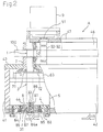
- 4 designates a machine base, a front housing 41 and a side housing 42 are attached to the machine base 4, and an upper plate 43 is attached to the housings 41, 42.
- An electric motor 5 functioning as a driving source for a movable die 2 which will be described later is disposed in the front portion of the machine base 4.
- a servomotor is used as the electric motor 5.
- the servomotor used as the electric motor 5 comprises a hole (not shown) which is concentric with the axis and vertically passed therethrough.
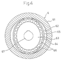
- the movable die 2 is connected to the rotor (not shown) of the electric motor 5 through a reduction mechanism 6 having a configuration which is illustratively shown in Fig. 4.
- the reduction mechanism 6 of Fig. 4 has a fundamental configuration wherein internal teeth 62 formed on an input rotor 61 engage with a part of external teeth 65 of a flexible pipe 64 which is fitted outward onto an elliptical output rotor 63 through a number of balls 66 and deformed into an elliptical shape.
- the rotor of the electric motor 5 is connected to the input rotor 61, and the movable die 2 is connected to the output rotor 61.
- a hole 67 which communicates with the above-mentioned hole of the electric motor 5 is formed at the center of the output rotor 61.
- the stationary die 1 is integrated with a middle portion in the axial direction of a shaft body 3 which portion is close to the upper end of the shaft body. As shown in Figs. 6 and 7, the stationary die 1 is provided with a slit 11 of an opening width which corresponds to the thickness of a strip material 100.
- a downward taper portion 31 is disposed at the lower end of the shaft body 3, and a key way 32 is formed on the downward taper portion 31.
- the movable die 2 comprises at a predetermined position along the circumferential direction a pair of pressing die portions 21, 21 which oppose each other in the circumferential direction, and is formed into a cylindrical shape having an opening 22 for introducing the strip material 100 at a position opposite to the pressing die portions 21, 21.
- a one-split mounting member 7 is clamped and fixed to the lower end of the movable die 2.
- a flange 71 of the mounting member 7 is concentrically fixed by using mounting screws 72 to the output rotor 63 of the reduction mechanism 6.
- the downward taper portion 31 of the lower end of the shaft body 3 is fitted into an upward spread shaped mounting hole 81 formed in the mounting member 8.
- a key 83 is fittingly attached to the key way 32 of the downward taper portion 31 and a key way 82 disposed on the mounting hole 81.
- a spacer 84 is superposed on the lower face of the mounting member 8, and a washer 87 is superposed on the lower face at a hole 84a of the spacer 84.
- a clamping bolt 86 passed through the washer 87 is screwed into a tapped hole 33 formed at the lower end of the shaft body 3. Under the state where the head 86a of the clamping bolt 86 is superposed on the washer 87, the downward taper portion 31 of the shaft body 3 is clamped and fixed to the upward spread shaped mounting hole 81 of the mounting member 8.
- the mounting member 8 comprises a mounting flange 88.
- the shaft body 3 attached to the mounting member 8 is passed from the lower side of the machine base 4 and through an opening 44 opened in the machine base 4, and through the hole (not shown) of the electric motor 5, the hole 67 of the reduction mechanism 6, and the interior of the movable die 2.
- the mounting member 8 is fitted into the opening 44 of the machine base 4, and the mounting flange 88 of the mounting member 8 is superposed on the lower face of the machine base 4.
- the mounting member 8 is fixed to the machine base 4 by screwing mounting bolts 85 into tapped holes 45 in the side of the machine base 4 from the lower side, the mounting bolts 85 being passed through bolt-passing holes 8a of the mounting flange 88 and the bolt-passing holes 84a of the spacer 84 which is superposed on the lower face of the mounting member 8.
- a fitting plate 47 is attached to the upper plate 43 through a supporting body 46.
- An electric motor 9 is disposed on the fitting plate 47 as shown in Fig. 2. Either of feed rollers 92, 93 is interlocked with the rotating shaft 91 of the electric motor 9 (see Figs. 6 and 7).
- the slit 11 of the stationary die 1 and the pair of pressing die portions 21 of the movable die 2 are accurately positioned under the nonoperation state shown in Fig. 6.
- the stationary die 1 since the stationary die 1 is integrated with the shaft body 3, the downward taper portion 31 of the shaft body 3 is fitted into the upward spread shaped mounting hole 81 of the mounting member 8 so that the shaft body 3 is erected in a direction perpendicular to the mounting member 8 and centered, and the shaft body 3 is accurately positioned by the key 83 in the circumferential direction, the slit 11 of the stationary die 1 and the pair of pressing die portions 21 of the movable die 2 can be positioned with high preciseness and accuracy and without requiring a special adjusting work.
- Fig. 6 shows the nonoperation state of the movable die 2 with respect to the stationary die 1 during a bending process.
- the strip material 100 is passed between the upper plate 43 and the fitting plate 47 to be supplied between feed rollers 92, 93 from behind.
- Intermittent rotation of the feed rollers 92, 93 owing to the driving of the electric motor 9 causes the strip material 100 to be intermittently fed out forward through the slit 11 of the stationary die 1.
- the movable die 2 is rotated by a predetermined amount in the forward or reverse direction when the feed of the strip material 100 is halted.
- Fig. 7 shows a state where the movable die 2 is rotated by the predetermined amount in the forward direction X.
- the strip material 100 is pressed by the left pressing die portion 21 of the movable die 2 against a right outlet corner 11b of the slit 11, to be bent in the rightward direction.
- the strip material 100 is pressed by the right pressing die portion 21 of the movable die 2 against a left outlet corner 11a of the slit 11, to be bent in the leftward direction.
- the bend angle of the strip material 100 corresponds to the rotation angle of the movable die 2.
- the existing shaft body 3 is to be replaced with another shaft body 3 comprising a stationary die 3 having a slit 11 of a different opening width
- the followings are conducted.
- the plural (for example, six) mounting bolts 85 ⁇ by which the mounting member 8 is fixed to the machine base 4 are removed.
- the mounting member 8, the spacer 84, and the shaft body 3 are pulled out to the lower side of the machine base 4 to be removed away.
- the mounting member 8 is fixed to the machine base 4 by using the mounting bolts 85 ⁇ .
- the mounting member 8, the spacer 84, etc. may be reused to be attached to the shaft body 3 for replacement. Such a work of replacing the shaft body 3 is the one which also the user can easily conduct. In this work, it is not necessary to again adjust the parallelism of the pressing die portions 21, 21 of the movable die 2.
- the movable die 2 is formed into a cylindrical shape so that the necessity of adjusting the parallelism of the pressing die portions 21, 21 is completely eliminated, and the bending process is allowed to be conducted without twisting the movable die 2 by transmitting the transmission of the rotation force against the movable die 2 only to one end of the movable die 2, so that the rotation of the electric motor 5 is transmitted only to the one end of the movable die 2 through the rotation transmission mechanism formed by the reduction mechanism 6.
- a twist of a movable die during a bending process is prevented from occurring by forming the movable die into a cylindrical shape, and the rotation is transmitted to the movable die through only its one end. Consequently, the replacement of a stationary die integrated with a shaft body can easily be conducted without accompanying difficult works such as the adjustment of the parallelism of pressing die portions of the movable die, and the disassemble of gears. Therefore, also the user can easily replace the stationary die.
- the apparatus for bending a strip material according to the invention can be applied not only to a process of bending a band blade, but also to a process of bending a strip material of another kind in a similar manner.
Landscapes
- Engineering & Computer Science (AREA)
- Mechanical Engineering (AREA)
- Bending Of Plates, Rods, And Pipes (AREA)
- Shaping Of Tube Ends By Bending Or Straightening (AREA)
Applications Claiming Priority (2)
| Application Number | Priority Date | Filing Date | Title |
|---|---|---|---|
| PCT/JP1993/000818 WO1995000266A1 (fr) | 1993-06-17 | 1993-06-17 | Appareil a cintrer une plaque de bande |
| CA002120037A CA2120037C (fr) | 1993-06-17 | 1993-06-17 | Machine pour cintrer un materiau en bande |
Publications (3)
| Publication Number | Publication Date |
|---|---|
| EP0657231A1 true EP0657231A1 (fr) | 1995-06-14 |
| EP0657231A4 EP0657231A4 (fr) | 1995-11-08 |
| EP0657231B1 EP0657231B1 (fr) | 1998-09-09 |
Family
ID=25677145
Family Applications (1)
| Application Number | Title | Priority Date | Filing Date |
|---|---|---|---|
| EP93913538A Expired - Lifetime EP0657231B1 (fr) | 1993-06-17 | 1993-06-17 | Appareil a cintrer une plaque de bande |
Country Status (5)
| Country | Link |
|---|---|
| US (1) | US5507168A (fr) |
| EP (1) | EP0657231B1 (fr) |
| CA (1) | CA2120037C (fr) |
| DE (1) | DE69320972T2 (fr) |
| WO (1) | WO1995000266A1 (fr) |
Cited By (1)
| Publication number | Priority date | Publication date | Assignee | Title |
|---|---|---|---|---|
| CN104785596A (zh) * | 2015-04-14 | 2015-07-22 | 四川和鼎环保工程有限责任公司 | 一种钣金加工装置 |
Families Citing this family (14)
| Publication number | Priority date | Publication date | Assignee | Title |
|---|---|---|---|---|
| KR0182069B1 (ko) * | 1995-06-22 | 1999-04-01 | 송병준 | 컷팅블레이드의 절곡시스템 |
| US5881591A (en) * | 1996-08-13 | 1999-03-16 | Ondracek; Carl | Automatic channel letter bending machine |
| US6705145B1 (en) * | 1999-11-19 | 2004-03-16 | Matsushita Electric Industrial Co., Ltd. | Method of processing bent and deformed portion of metal material |
| FI110491B (fi) * | 2000-09-26 | 2003-02-14 | Rondeco Oy | Levynkäsittelylaite |
| KR100388542B1 (ko) * | 2000-12-01 | 2003-06-25 | 박홍순 | 예각 성형이 우수한 컷팅 블레이드의 절곡장치 |
| US20050005664A1 (en) * | 2003-07-09 | 2005-01-13 | Wesley Scott | System and method for bending strip material to create cutting dies |
| JP2006055896A (ja) * | 2004-07-20 | 2006-03-02 | Suehiro Mizukawa | 帯板材の曲げ加工方法及びその曲げ加工装置 |
| JP4435035B2 (ja) * | 2005-05-27 | 2010-03-17 | 聰長 占部 | スチール・ルール抜型の自動曲げ機における刃材の両端切断装置 |
| JP2007111768A (ja) * | 2005-10-21 | 2007-05-10 | Toshinaga Urabe | スチール・ルール抜型の自動曲げ機 |
| DE102007016083A1 (de) * | 2006-05-31 | 2007-12-06 | Mizukawa, Suehiro, Settsu | Verfahren und Vorrichtung zum Biegen eines Messerelements |
| CN102076451A (zh) * | 2008-06-27 | 2011-05-25 | 朴洪顺 | 板材切割装置 |
| CN108296331A (zh) * | 2018-02-10 | 2018-07-20 | 清远韶兴新能源科技有限公司 | 一种便于更换弯管模的数控弯管机 |
| CN108202117A (zh) * | 2018-03-20 | 2018-06-26 | 湖州汇松机电科技有限公司 | 一种电子元器件针脚弯曲模具 |
| CN122076851B (zh) * | 2026-04-23 | 2026-07-24 | 成都曙东科技有限责任公司 | 一种建筑工程折弯用自适应联动夹持辅助装置 |
Family Cites Families (6)
| Publication number | Priority date | Publication date | Assignee | Title |
|---|---|---|---|---|
| US757078A (en) * | 1903-08-28 | 1904-04-12 | James J Wood | Bending-machine. |
| DE2215490A1 (de) * | 1972-03-29 | 1973-10-04 | Peddinghaus Carl Ullrich Dr | Biegemaschine fuer insbesondere betonstahlstaebe |
| IT1125327B (it) * | 1979-02-28 | 1986-05-14 | Piegatrici Macch Elettr | Macchina staffatrice |
| JPH0661583B2 (ja) * | 1987-06-10 | 1994-08-17 | 末弘 水河 | 帯刃の曲げ加工方法 |
| JPH01258818A (ja) * | 1988-04-05 | 1989-10-16 | Fujitsu Ltd | 平板の曲げ加工方法 |
| AT399676B (de) * | 1990-01-12 | 1995-06-26 | Evg Entwicklung Verwert Ges | Biegemaschine zum biegen von stabförmigem material |
-
1993
- 1993-06-17 DE DE69320972T patent/DE69320972T2/de not_active Expired - Fee Related
- 1993-06-17 WO PCT/JP1993/000818 patent/WO1995000266A1/fr not_active Ceased
- 1993-06-17 CA CA002120037A patent/CA2120037C/fr not_active Expired - Fee Related
- 1993-06-17 US US08/211,557 patent/US5507168A/en not_active Expired - Lifetime
- 1993-06-17 EP EP93913538A patent/EP0657231B1/fr not_active Expired - Lifetime
Non-Patent Citations (2)
| Title |
|---|
| No further relevant documents disclosed * |
| See also references of WO9500266A1 * |
Cited By (1)
| Publication number | Priority date | Publication date | Assignee | Title |
|---|---|---|---|---|
| CN104785596A (zh) * | 2015-04-14 | 2015-07-22 | 四川和鼎环保工程有限责任公司 | 一种钣金加工装置 |
Also Published As
| Publication number | Publication date |
|---|---|
| DE69320972T2 (de) | 1999-02-11 |
| EP0657231A4 (fr) | 1995-11-08 |
| US5507168A (en) | 1996-04-16 |
| DE69320972D1 (de) | 1998-10-15 |
| CA2120037C (fr) | 1998-01-06 |
| EP0657231B1 (fr) | 1998-09-09 |
| CA2120037A1 (fr) | 1994-12-18 |
| WO1995000266A1 (fr) | 1995-01-05 |
Similar Documents
| Publication | Publication Date | Title |
|---|---|---|
| EP0657231B1 (fr) | Appareil a cintrer une plaque de bande | |
| US20020130153A1 (en) | Tool-less feedroll for wire feeder | |
| JPH0828648A (ja) | 外部循環式ボールねじ装置 | |
| JP4932628B2 (ja) | 筒部内周部切削加工用被加工物保持装置 | |
| JP2648889B2 (ja) | 帯板材の曲げ加工装置 | |
| DE102025112544A1 (de) | Elektrisches kraftwerkzeug | |
| JPH10156643A (ja) | 締め付け機の間隔調整装置 | |
| KR20160122962A (ko) | Cnc 공작기계의 다축 가공을 위한 고정용 지그의 공작물 회전 장치 | |
| KR100224100B1 (ko) | 띠판재의 절곡 가공장치 | |
| JP3093162B2 (ja) | 回転体取付構造 | |
| JPS62248527A (ja) | 曲げ加工装置 | |
| JPWO1995000266A1 (ja) | 帯板材の曲げ加工装置 | |
| JPH0523745A (ja) | 曲げ装置 | |
| US4633920A (en) | Positioning device | |
| US5833543A (en) | Apparatus for forming a slot in a headless screw | |
| CN222198510U (zh) | 一种精准对位的汽车零配件加工用冲床 | |
| KR101874597B1 (ko) | 태핑 장치 | |
| CN223889454U (zh) | 一种具有调节结构的滑轨式夹具总成 | |
| CN215699717U (zh) | 一种减速机安装板 | |
| JP2941999B2 (ja) | 自動ドライバ | |
| KR200280982Y1 (ko) | 에어를 이용한 순간 코킹장치 | |
| US20070089472A1 (en) | Automatic bending machine for manufacturing of steel rule cutting dies | |
| JP2004202582A (ja) | 帯板材曲げ加工装置用の可動型製造方法 | |
| JPH07153170A (ja) | フレキシブルディスク装置のキャリッジ機構 | |
| JPH0924501A (ja) | 切断機 |
Legal Events
| Date | Code | Title | Description |
|---|---|---|---|
| PUAI | Public reference made under article 153(3) epc to a published international application that has entered the european phase |
Free format text: ORIGINAL CODE: 0009012 |
|
| AK | Designated contracting states |
Kind code of ref document: A1 Designated state(s): DE FR GB |
|
| 17P | Request for examination filed |
Effective date: 19950421 |
|
| A4 | Supplementary search report drawn up and despatched | ||
| AK | Designated contracting states |
Kind code of ref document: A4 Designated state(s): DE FR GB |
|
| 17Q | First examination report despatched |
Effective date: 19961015 |
|
| GRAG | Despatch of communication of intention to grant |
Free format text: ORIGINAL CODE: EPIDOS AGRA |
|
| GRAG | Despatch of communication of intention to grant |
Free format text: ORIGINAL CODE: EPIDOS AGRA |
|
| GRAH | Despatch of communication of intention to grant a patent |
Free format text: ORIGINAL CODE: EPIDOS IGRA |
|
| GRAH | Despatch of communication of intention to grant a patent |
Free format text: ORIGINAL CODE: EPIDOS IGRA |
|
| GRAA | (expected) grant |
Free format text: ORIGINAL CODE: 0009210 |
|
| AK | Designated contracting states |
Kind code of ref document: B1 Designated state(s): DE FR GB |
|
| ET | Fr: translation filed | ||
| REF | Corresponds to: |
Ref document number: 69320972 Country of ref document: DE Date of ref document: 19981015 |
|
| PLBE | No opposition filed within time limit |
Free format text: ORIGINAL CODE: 0009261 |
|
| STAA | Information on the status of an ep patent application or granted ep patent |
Free format text: STATUS: NO OPPOSITION FILED WITHIN TIME LIMIT |
|
| 26N | No opposition filed | ||
| PGFP | Annual fee paid to national office [announced via postgrant information from national office to epo] |
Ref country code: GB Payment date: 20000526 Year of fee payment: 8 |
|
| PGFP | Annual fee paid to national office [announced via postgrant information from national office to epo] |
Ref country code: FR Payment date: 20000616 Year of fee payment: 8 |
|
| PG25 | Lapsed in a contracting state [announced via postgrant information from national office to epo] |
Ref country code: GB Free format text: LAPSE BECAUSE OF NON-PAYMENT OF DUE FEES Effective date: 20010617 |
|
| GBPC | Gb: european patent ceased through non-payment of renewal fee |
Effective date: 20010617 |
|
| PG25 | Lapsed in a contracting state [announced via postgrant information from national office to epo] |
Ref country code: FR Free format text: LAPSE BECAUSE OF NON-PAYMENT OF DUE FEES Effective date: 20020228 |
|
| PGFP | Annual fee paid to national office [announced via postgrant information from national office to epo] |
Ref country code: DE Payment date: 20030603 Year of fee payment: 11 |
|
| PG25 | Lapsed in a contracting state [announced via postgrant information from national office to epo] |
Ref country code: DE Free format text: LAPSE BECAUSE OF NON-PAYMENT OF DUE FEES Effective date: 20050101 |