EP0657357A1 - Vorrichtung zum einbringen eines schirms in eine hülle - Google Patents
Vorrichtung zum einbringen eines schirms in eine hülle Download PDFInfo
- Publication number
- EP0657357A1 EP0657357A1 EP94903036A EP94903036A EP0657357A1 EP 0657357 A1 EP0657357 A1 EP 0657357A1 EP 94903036 A EP94903036 A EP 94903036A EP 94903036 A EP94903036 A EP 94903036A EP 0657357 A1 EP0657357 A1 EP 0657357A1
- Authority
- EP
- European Patent Office
- Prior art keywords
- storage
- umbrella
- sacks
- support member
- movable support
- Prior art date
- Legal status (The legal status is an assumption and is not a legal conclusion. Google has not performed a legal analysis and makes no representation as to the accuracy of the status listed.)
- Granted
Links
Images


Classifications
-
- B—PERFORMING OPERATIONS; TRANSPORTING
- B65—CONVEYING; PACKING; STORING; HANDLING THIN OR FILAMENTARY MATERIAL
- B65B—MACHINES, APPARATUS OR DEVICES FOR, OR METHODS OF, PACKAGING ARTICLES OR MATERIALS; UNPACKING
- B65B67/00—Apparatus or devices facilitating manual packaging operations; Sack holders
- B65B67/12—Sack holders, i.e. stands or frames with means for supporting sacks in the open condition to facilitate filling with articles or materials
-
- A—HUMAN NECESSITIES
- A45—HAND OR TRAVELLING ARTICLES
- A45B—WALKING STICKS; UMBRELLAS; LADIES' OR LIKE FANS
- A45B25/00—Details of umbrellas
- A45B25/24—Protective coverings for umbrellas when closed
-
- B—PERFORMING OPERATIONS; TRANSPORTING
- B65—CONVEYING; PACKING; STORING; HANDLING THIN OR FILAMENTARY MATERIAL
- B65B—MACHINES, APPARATUS OR DEVICES FOR, OR METHODS OF, PACKAGING ARTICLES OR MATERIALS; UNPACKING
- B65B43/00—Forming, feeding, opening or setting-up containers or receptacles in association with packaging
- B65B43/12—Feeding flexible bags or carton blanks in flat or collapsed state; Feeding flat bags connected to form a series or chain
- B65B43/14—Feeding individual bags or carton blanks from piles or magazines
-
- B—PERFORMING OPERATIONS; TRANSPORTING
- B65—CONVEYING; PACKING; STORING; HANDLING THIN OR FILAMENTARY MATERIAL
- B65B—MACHINES, APPARATUS OR DEVICES FOR, OR METHODS OF, PACKAGING ARTICLES OR MATERIALS; UNPACKING
- B65B43/00—Forming, feeding, opening or setting-up containers or receptacles in association with packaging
- B65B43/42—Feeding or positioning bags, boxes, or cartons in the distended, opened, or set-up state; Feeding preformed rigid containers, e.g. tins, capsules, glass tubes, glasses, to the packaging position; Locating containers or receptacles at the filling position; Supporting containers or receptacles during the filling operation
- B65B43/44—Feeding or positioning bags, boxes, or cartons in the distended, opened, or set-up state; Feeding preformed rigid containers, e.g. tins, capsules, glass tubes, glasses, to the packaging position; Locating containers or receptacles at the filling position; Supporting containers or receptacles during the filling operation from supply magazines
Definitions
- This invention relates to a storage device for wet umbrellas that automatically wraps an umbrella and places it in sacks. It can be used, for example, at an entrance of hotels, shops and department stores, so that when it is raining, wet umbrellas can be adequately handled and stored.
- the present invention is proposed to solve such the provblems and to provide a simple structured device so that umbrellas can easily be stored in storage sacks.
- the storage device of the present invention is comprised of: a body for filling a number of storage sacks therein; a movable support member being arranged in the device body and being movable in vertical directions; a foot pedal for lowering said movable support member; and open control levers that open the storage sacks in connection with the descending motion of said movable support member.
- a number of storage sacks are stored in a box and the box is filled in the device's body and said storage sacks are suspended by means of a hanger in order to store themselves in said box (that is, in order to store said storage sacks in said box).
- said open control levers are structured separately so that a pair of levers move and rotate independently relative to said movable support member.
- a means for moving and rotating each open control lever in a direction, in which direction each of said levers contacts with said storage sacks, is preferably provided separately.
- a spring is preferable.
- said open control levers can be comprised of bucket-shaped members made with a slippery material (e.g. resin material such as plastic).
- the aforementioned device body is not limited just by its case. It can be structured by pillars and transparent members can be arranged between the pillars.
- the movable support member when the foot pedal is pressed, the movable support member is lowered and the open control levers open the storage sacks in connection with such descending motion of said movable support member. And then, wet umbrellas can be stored in the storage sacks by inserting each one into each opening of the storage sack.
- the open control levers in case that said open control levers are structured separately, a pair of levers move and rotate independently relative to said movable support member respectively, and in case that the means for moving and rotating each open control lever in a direction, in which direction said open control levers contact with the storage sacks, is structured separately and independently each other, said opening can open exactly althought misregistration of said opening is generated.
- a large number of storage sacks can be easily stored in the device body collectively and rapidly. Additionally, since they are packed in one box, it is easy to carry or store many sacks before they are filled in the storage device. Furthermore, the required costs can be minimized.
- each open control lever moves and rotates in such a direction as make contact with the storage sacks. Since each lever independently moves and rotates to open the storage sacks in connection with the descending motion of the movable support member, and then, the pair of levers enter into the openings of storage sacks to open them, said opening can be opened exactly in despite of any misregistration generated around the opening.
- said open control levers are made of bucket-shaped members being made of slippery materials such as resin material (e.g.) plastic, integrally, the insertion of umbrellas can be easier and with greater certainty.
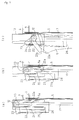
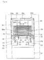
- the charactor (1) is a quadratic prismshaped device body situated on a bed plate (2); closing cover (3) is installed on top of the device body (1).
- a fixed support base (4) is mounted inside of the upper device body (1); a hanger (6), which is suspended to retain storage sacks (5), is set on the fixed support base (4).
- the hanger (6) is comprised of a bar and the like in the form of a box (top-open rectangle-shaped); the base (6a) is anchored to a hook (not illustrated) and then mounted on a fixed support base (4); and the hanger (6) is installed by hitching both ends (6a, 6b) to anchor holes (8a) of support member (8) fixed to the fixed support base (4) for easy removal.
- the top part of the storage sack (5) has an opening (5a); the upper end (51a) of the fore side (51) of the opening is folded forward in a U-shape; the upper end (52a) of the rear side (52) is projected above that of the fore side (51); and a pair of locking holes (5b) are provided at the upper end of the projected portion.
- a movable pressure plate (9) is located along a pair of guide bars (10, 10) on the rear face of storage sacks (5); and the pressure plate (9) is constantly pressed against the rear face of storage sacks (5) by a coil spring (10a) penetrating into each guide bar.
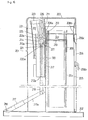
- the guide members (14, 15) are mounted ahead of said fixed support base (4); a movable support member (11) in an inverted L-shape (front view) is penetrated for storage to move vertically in holes (14b,15b) formed on the horizontal arms (14a, 15a) of such guide members.
- a roller (12) is provided at the upper end of the movable support member (11) to rotate freely; the roller (12) is arranged along with a box type guide rail (13) mounted ahead of the fixed support base (4) to move it vertically.
- a foot pedal (16) is provided on said bed p!ate (2) to lower said movable support member (11). As shown in Figure 4, the foot pedal (16) is mounted or installed by a hinge (17) to move vertically on the bed plate (2).
- a lever (18) is integrally mounted to the pedal (16); the lever (18) is connected to the lower end of said movable support member (11) through a link (19).
- the charactor (20) is a return spring being provided to return the movable support member (11) above; the return spring (20) is arranged a position between a spring bearing (21) and a horizontal arm (14a) of said guide member (14) in a contracted condition; said spring bearing is comprised of a clip or similar and is mounted to the movable support member (11).
- a pair of open control levers (22, 22) are rotatably provided on the upper central position of said movable support member (11); said levers (22, 22) enter into the openings (5a) of storage sacks and open the openings (5a). Both ends of said levers (22, 22) are integrally connected in a bottom-open rectangle-shape as in the illustrated example.
- a moving control arm (23) is integrally provided on one end of both levers (22, 22) to rotate said levers (22, 22); a contacting plate (24) is provided under the arm (23) integral to said guide rail (13); the contacting plate (24) moves to rotate both levers (22, 22) in clockwise direction in Figure 4 by contacting with said arm (23).
- the charactor (25) represents a coil spring; the coil spring (25) is set as a tension coil spring between said moving control arm (23) and the spring bearing (26) connected vertically to one end of the movable support member (11) so it can rotate freely.
- the lower end of said open control levers (22, 22) move and rotate constantly in such a direction as storaging sacks (5).
- the lower end of the open control lever (22) can constantly be moved to rotate in such a direction as storaging sacks (5) by locking one end of a helical spring to the movable support member (11) and by locking the other end of the spring to said open control lever (22); in this case, the helical spring and the like can be arranged around the movable support member (11) close to said open control lever (22).
- the sack (5) in which an umbrella is stored can be removed from the hanger (6), tearing the upper locking holes (5b) of the storage sack (5) by pulling the sack out and lowering the device body (1).
- the sack wrapping an umbrella can easily be removed from the device body (1).
- umbrellas can easily be stored into each storage sack completely without using a motor or a vacuum pump and the like in order to open the openings of storage sacks easily and completely.
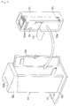
- a number of storage sacks (104) are firstly stored in a box (105); and the box in which a number of storage sacks are stored is charged in a device body (101).
- a storage sack used in the embodiment shown from Figure 8 through Figure 12 is shown in Figure 8(a) and 8(b).
- the storage sack (104) comprises a plastic film and the like, and as shown in Figure 8, it is formed in a flat cylindershape; the upper part of the storage sack has an opening (4a); the upper end (141a) of the fore side (141) of the opening (104a) is folded in a U-shape toward the rear side (142); and the upper end (142a) of the rear side (142) projects further than that of the fore side (141).
- a pair of locking holes (104b) are provided at the projected portion upward.
- the aforementioned box (105) is made of corrugated fiberboard; as shown in Figure 9, it is formed in the shape of a longitudinal rectangular parallel pipe.
- a pair of bar-shaped hangers (107, 107) are provided inside the upper part of said box (105) and said hangers (1007, 107) penetrate locking holes (104b) of said storage sack (104).
- the hanger (107) is installed to support plates (108a, 108b) fixed to the upper surface inside the box (105).
- a number of storage sacks (104) can be suspended to retain a state such that the fore side (141) faces the left-hand side as shown in Figure 10.
- a pressure plate (See Figure 12) is arranged on the rear face of the storage sacks (104); the pressure plate presses the storage sacks with an elastic member.
- rubber bands (110) are applied as the elastic members; both ends of the rubber bands (110) are anchored to a hook (181) provided at both sides of the supporting plate (108a).
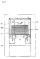
- an opening (151) which can open along the perforating scores (105a) is provided on the front face of the box (105); the box (105) or the storage sacks (104) which are stored in the box are transferred and stored without opening the opening (51) when they are not used.
- the switch door (106) provided on the rear side of the device body (1011) to place the box (105) into the device body (1) being while opening the opening (151).
- a box type fixed support member is integrally provided inside the device body (101) on the upper part of the box (105) placed in the device body; the positioning is done so as to contact the fore side of the fixed support member (111) with the front face of said box (105).
- the box (105) storing storage sacks for umbrellas is filled from the rear side to the device body (101), however, the box can be filled from the top of the device body (101) by configuring, for example, a cover (103) can be open.
- a frame body (101b) can be applied as part of the device body to place the box (105) in the frame (101b) to determine the specified position to retain the box without covering up all faces of the box (105) by the device body (101).
- the opening (4a) of the storage sack (4) can be opened by actuating vacuum suction in the aforementioned prior embodiment without using the open control lever (22) to open the opening (4a) in accordance with the embodiment shown in Figure 1 to Figure 7.
- a pair of horizontal open control levers are structured to move and rotate independently.
- a left-hand side tension coil spring (224) is applied between a left-hand side rotation control arm (223) and said guide rail (216); a right-hand side tension coil spring is applied between a right-hand side rotation control arm (223) and said guide member (212).
- contacting plates (225, 225) are integrally provided on said guide rail (216) and guide member (212); the contacting plates make each open control lever (222) to rotate it in the reverse direction toward a storage sack (4) by contacting with the rotation control arm (223) when each open control lever (222) moves lower together with a movable support member (214).
- Tension coil spring is exemplified as a means of making each open control lever (222, 222) rotate toward storage sacks (204), however, for example, a helical spring can be applied as the means, as well.
- each open control lever (222) can be inserted into the opening (204a) by lowering in a good state of contact with the front face of the upper rear end (242a) of the forefront storage sack (204) even some longitudinal misregistration of the opening (204a) in a direction across from the forefront storage sack (204) is generated.
- the foot pedal is continuously pedaled until an umbrella stored in a storage sack is removed from the device body; when the foot pedal is released after the storage sack is taken out, the original condition will return by working a return spring to ascend the movable support member.
- the forefront storage sack is maintains the opening by applying anchoring means to keep lowering the movable support member by depressing the foot pedal until the stored umbrella is taken out when the foot pedal is released; for example, as shown in Figure 16, a plurality of locking grooves (226) can be formed on the movable support member (214) and an anchoring claw (227) which hitches to said grooves can be applied to the guide member (213) integrally.
- the movable support member (214) When an umbrella stored in a storage sack (204) opens the opening (204a) and the umbrella with a sack is removed from the device body, the movable support member (214) will incline in the direction to release the anchoring to an anchoring claw (227) through the open control lever (222). Next, the anchoring locking groove (214a) to anchoring claw (227) is released and the movable support member (214) automatically returns to the original position for ascending by elastic rebound of the return spring (220).
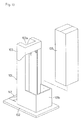
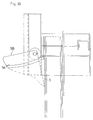
- Figures 18 to 20 show the other embodiment of the present invention.
- sign (328) shows a bucket-shaped member formed from plastic integrally. Umbrella insertion can be done easily and completely thanks to the shape of this bucket-shaped member (328).
- Open storage sacks (5) with bucket-shaped member (328) are shown in Figure 19s and 20, however, a detailed explanation is skipped because the state shown in Figure 19 and Figure 20 is almost similar to that in Figure 7(a) to 7(c).
- the aforementioned embodiment is just an example, therefore structural changes are possible within the purpose of the present invention from time to time.
- an opening of a storage sack can be opened by operating the open control levers in connection with lowering a movable support member by depressing a foot pedal; and then, a wet umbrella can easily be stored by inserting it in the open opening of the storage sack.
- the present invention when a number of storage sacks are stored in a box being placed in the device body, many such storage sacks can easily be stored in the device collectively and rapidly. Additionally, since the storage sacks are stored in a box collectively, it is easy to carry and store even before the stored box is placed in the device.
- said open control levers when a pair of open control levers are separately structured to move and rotate independently relative to the movable support member, said open control levers can completely enter into and open said opening, althoutht some misregistration of the opening is generated across the longitudinal direction of the storage sack.
Landscapes
- Engineering & Computer Science (AREA)
- Mechanical Engineering (AREA)
- Holders For Apparel And Elements Relating To Apparel (AREA)
- Auxiliary Apparatuses For Manual Packaging Operations (AREA)
- Supplying Of Containers To The Packaging Station (AREA)
- Walking Sticks, Umbrellas, And Fans (AREA)
Applications Claiming Priority (7)
| Application Number | Priority Date | Filing Date | Title |
|---|---|---|---|
| JP4113193 | 1993-06-30 | ||
| JP41131/93U | 1993-06-30 | ||
| JP32107093A JP2777326B2 (ja) | 1993-11-26 | 1993-11-26 | 傘の袋収納装置 |
| JP321070/93 | 1993-11-26 | ||
| JP5321071A JP2813292B2 (ja) | 1993-11-26 | 1993-11-26 | 傘の袋収納装置 |
| JP321071/93 | 1993-11-26 | ||
| PCT/JP1993/001852 WO1995001281A1 (en) | 1993-06-30 | 1993-12-22 | Apparatus for getting an umbrella received into an umbrella cover |
Publications (3)
| Publication Number | Publication Date |
|---|---|
| EP0657357A1 true EP0657357A1 (de) | 1995-06-14 |
| EP0657357A4 EP0657357A4 (de) | 1995-11-29 |
| EP0657357B1 EP0657357B1 (de) | 1998-04-22 |
Family
ID=27290723
Family Applications (1)
| Application Number | Title | Priority Date | Filing Date |
|---|---|---|---|
| EP94903036A Expired - Lifetime EP0657357B1 (de) | 1993-06-30 | 1993-12-22 | Vorrichtung zum einbringen eines schirms in eine hülle |
Country Status (8)
| Country | Link |
|---|---|
| US (1) | US5586683A (de) |
| EP (1) | EP0657357B1 (de) |
| KR (1) | KR0167023B1 (de) |
| CN (3) | CN1096437A (de) |
| DE (1) | DE69318164T2 (de) |
| ES (1) | ES2115925T3 (de) |
| SG (1) | SG47456A1 (de) |
| WO (1) | WO1995001281A1 (de) |
Cited By (4)
| Publication number | Priority date | Publication date | Assignee | Title |
|---|---|---|---|---|
| FR2732573A1 (fr) * | 1995-04-04 | 1996-10-11 | Daito Sound Co Ltd | Dispositif d'ensachage de parapluies |
| EP0770550A1 (de) * | 1995-10-24 | 1997-05-02 | Wei, Yao-ming | Vorrichtung zum Aufweiten eines Verpackungsbeutels |
| EP1659065A4 (de) * | 2003-08-27 | 2008-02-27 | Muraharu Seisakusho Kk | Artikellagerungsvorrichtung |
| EP1834880A4 (de) * | 2004-11-25 | 2012-01-18 | Niikura Scales Co Ltd | Regenschirmbeutelaufbewahrungsvorrichtung |
Families Citing this family (2)
| Publication number | Priority date | Publication date | Assignee | Title |
|---|---|---|---|---|
| US6766996B1 (en) * | 2001-07-16 | 2004-07-27 | Reid-Ashman Manufacturing, Inc. | Manipulator |
| CN109288220B (zh) * | 2018-10-31 | 2020-05-29 | 黄海英 | 一种自动雨伞套装置 |
Family Cites Families (15)
| Publication number | Priority date | Publication date | Assignee | Title |
|---|---|---|---|---|
| GB1373175A (en) * | 1972-01-10 | 1974-11-06 | Kristiansen A H | Apparatus for the opening and securing of carrier bags during filling of commodities |
| JPS5315670Y2 (de) * | 1972-09-20 | 1978-04-25 | ||
| SE369373B (de) * | 1972-11-24 | 1974-08-26 | Lundin B Ab | |
| JPS58149914U (ja) * | 1982-03-31 | 1983-10-07 | 老月 太郎 | 傘収納袋 |
| JPS59118711U (ja) * | 1983-01-31 | 1984-08-10 | 株式会社寺岡精工 | 充填包装機における包装用袋の支持構造 |
| JPS60134817A (ja) * | 1983-12-19 | 1985-07-18 | 鷲山精電工業株式会社 | 傘入れ袋の自動開口保持機 |
| JPS62125708A (ja) * | 1985-11-26 | 1987-06-08 | Matsushita Electric Ind Co Ltd | スイツチ回路 |
| FR2592367A1 (fr) * | 1985-12-30 | 1987-07-03 | Castelletta Rene | Dispositif pour distribution de sacs en matiere plastique, en particulier sur des lieux de vente. |
| JPH01124120U (de) * | 1988-02-18 | 1989-08-23 | ||
| US5050743A (en) * | 1989-09-29 | 1991-09-24 | Unisys Corporation | Combined sack and tray system for mail collection |
| JPH0725377B2 (ja) * | 1990-05-21 | 1995-03-22 | 純市 滝本 | 傘収納袋支持装置 |
| JPH06102449B2 (ja) * | 1990-05-21 | 1994-12-14 | 純市 滝本 | 傘収納袋の自動開口装置 |
| JPH0495720U (de) * | 1991-01-10 | 1992-08-19 | ||
| JPH057611U (ja) * | 1991-01-17 | 1993-02-02 | 山田機械工業株式会社 | 傘袋支持装置 |
| US5310102A (en) * | 1992-06-01 | 1994-05-10 | Hougham John K | Apparatus for field sleeving of lettuce and other vegetables |
-
1993
- 1993-12-22 EP EP94903036A patent/EP0657357B1/de not_active Expired - Lifetime
- 1993-12-22 KR KR1019950700466A patent/KR0167023B1/ko not_active Expired - Fee Related
- 1993-12-22 WO PCT/JP1993/001852 patent/WO1995001281A1/ja not_active Ceased
- 1993-12-22 US US08/256,423 patent/US5586683A/en not_active Expired - Fee Related
- 1993-12-22 SG SG1996001815A patent/SG47456A1/en unknown
- 1993-12-22 DE DE69318164T patent/DE69318164T2/de not_active Expired - Fee Related
- 1993-12-22 ES ES94903036T patent/ES2115925T3/es not_active Expired - Lifetime
-
1994
- 1994-02-07 CN CN94101420A patent/CN1096437A/zh active Pending
- 1994-02-07 CN CN94101419A patent/CN1102968A/zh active Pending
- 1994-02-07 CN CN94101417A patent/CN1047564C/zh not_active Expired - Fee Related
Cited By (5)
| Publication number | Priority date | Publication date | Assignee | Title |
|---|---|---|---|---|
| FR2732573A1 (fr) * | 1995-04-04 | 1996-10-11 | Daito Sound Co Ltd | Dispositif d'ensachage de parapluies |
| EP0770550A1 (de) * | 1995-10-24 | 1997-05-02 | Wei, Yao-ming | Vorrichtung zum Aufweiten eines Verpackungsbeutels |
| EP1659065A4 (de) * | 2003-08-27 | 2008-02-27 | Muraharu Seisakusho Kk | Artikellagerungsvorrichtung |
| US7637081B2 (en) | 2003-08-27 | 2009-12-29 | Niikura Scales Co., Ltd. | Article storage device |
| EP1834880A4 (de) * | 2004-11-25 | 2012-01-18 | Niikura Scales Co Ltd | Regenschirmbeutelaufbewahrungsvorrichtung |
Also Published As
| Publication number | Publication date |
|---|---|
| KR950702923A (ko) | 1995-08-23 |
| DE69318164D1 (de) | 1998-05-28 |
| WO1995001281A1 (en) | 1995-01-12 |
| EP0657357B1 (de) | 1998-04-22 |
| CN1102968A (zh) | 1995-05-31 |
| HK1010453A1 (en) | 1999-06-17 |
| CN1096489A (zh) | 1994-12-21 |
| ES2115925T3 (es) | 1998-07-01 |
| KR0167023B1 (ko) | 1998-12-01 |
| DE69318164T2 (de) | 1998-08-20 |
| EP0657357A4 (de) | 1995-11-29 |
| CN1047564C (zh) | 1999-12-22 |
| US5586683A (en) | 1996-12-24 |
| CN1096437A (zh) | 1994-12-21 |
| SG47456A1 (en) | 1998-04-17 |
Similar Documents
| Publication | Publication Date | Title |
|---|---|---|
| US4687462A (en) | Process for the automatic insertion of box-shaped bags | |
| EP0657357A1 (de) | Vorrichtung zum einbringen eines schirms in eine hülle | |
| FR2521524A1 (fr) | Machine pour sceller des boites en carton avec dispositif d'ouverture immediate de la zone de scellement en marche | |
| US5655352A (en) | Storage device for wrapping (shopping) bags | |
| US5526631A (en) | Storage device for umbrella sacks | |
| CN103662118B (zh) | 一种下料机构 | |
| HK1010453B (en) | Apparatus for getting an umbrella received into an umbrella cover | |
| CN108792337B (zh) | 一种机械式扎口垃圾箱 | |
| US2711848A (en) | Packaging apparatus | |
| HK1010452B (en) | Apparatus for getting an umbrella received into an umbrella cover | |
| JP2777326B2 (ja) | 傘の袋収納装置 | |
| JP4268244B2 (ja) | 葉菜類の袋詰め装置 | |
| JPS63248610A (ja) | 雨傘袋形成装置 | |
| JPH0665204U (ja) | クリーニング済み衣服の立体包装用支持スタンド | |
| CN213200574U (zh) | 扫地机器人全纸包装箱 | |
| HK1017574B (en) | Apparatus for getting an article received into a cover | |
| JP2523125Y2 (ja) | 結束機 | |
| JP3002658U (ja) | 布団袋詰装置 | |
| JPS63137703U (de) | ||
| JPS6014645Y2 (ja) | エノキ茸自動包装装置 | |
| KR19980017394A (ko) | 쓰레기 저장장치 | |
| JP2000128118A (ja) | 葉菜類の袋詰め装置における葉菜類の詰込み装置 | |
| KR100848621B1 (ko) | 볼트용 포대 포장장치 | |
| JPS6128723Y2 (de) | ||
| JP2581861Y2 (ja) | 育苗容器展開装置 |
Legal Events
| Date | Code | Title | Description |
|---|---|---|---|
| PUAI | Public reference made under article 153(3) epc to a published international application that has entered the european phase |
Free format text: ORIGINAL CODE: 0009012 |
|
| 17P | Request for examination filed |
Effective date: 19950323 |
|
| AK | Designated contracting states |
Kind code of ref document: A1 Designated state(s): DE ES FR GB IT NL |
|
| A4 | Supplementary search report drawn up and despatched | ||
| AK | Designated contracting states |
Kind code of ref document: A4 Designated state(s): DE ES FR GB IT NL |
|
| 17Q | First examination report despatched |
Effective date: 19960229 |
|
| GRAG | Despatch of communication of intention to grant |
Free format text: ORIGINAL CODE: EPIDOS AGRA |
|
| GRAG | Despatch of communication of intention to grant |
Free format text: ORIGINAL CODE: EPIDOS AGRA |
|
| GRAH | Despatch of communication of intention to grant a patent |
Free format text: ORIGINAL CODE: EPIDOS IGRA |
|
| GRAH | Despatch of communication of intention to grant a patent |
Free format text: ORIGINAL CODE: EPIDOS IGRA |
|
| GRAA | (expected) grant |
Free format text: ORIGINAL CODE: 0009210 |
|
| AK | Designated contracting states |
Kind code of ref document: B1 Designated state(s): DE ES FR GB IT NL |
|
| ITF | It: translation for a ep patent filed | ||
| REF | Corresponds to: |
Ref document number: 69318164 Country of ref document: DE Date of ref document: 19980528 |
|
| REG | Reference to a national code |
Ref country code: ES Ref legal event code: FG2A Ref document number: 2115925 Country of ref document: ES Kind code of ref document: T3 |
|
| ET | Fr: translation filed | ||
| PG25 | Lapsed in a contracting state [announced via postgrant information from national office to epo] |
Ref country code: GB Free format text: LAPSE BECAUSE OF NON-PAYMENT OF DUE FEES Effective date: 19981222 |
|
| PLBE | No opposition filed within time limit |
Free format text: ORIGINAL CODE: 0009261 |
|
| STAA | Information on the status of an ep patent application or granted ep patent |
Free format text: STATUS: NO OPPOSITION FILED WITHIN TIME LIMIT |
|
| 26N | No opposition filed | ||
| PG25 | Lapsed in a contracting state [announced via postgrant information from national office to epo] |
Ref country code: NL Free format text: LAPSE BECAUSE OF NON-PAYMENT OF DUE FEES Effective date: 19990701 |
|
| GBPC | Gb: european patent ceased through non-payment of renewal fee |
Effective date: 19981222 |
|
| PG25 | Lapsed in a contracting state [announced via postgrant information from national office to epo] |
Ref country code: FR Free format text: LAPSE BECAUSE OF NON-PAYMENT OF DUE FEES Effective date: 19990831 |
|
| NLV4 | Nl: lapsed or anulled due to non-payment of the annual fee |
Effective date: 19990701 |
|
| REG | Reference to a national code |
Ref country code: FR Ref legal event code: ST |
|
| PG25 | Lapsed in a contracting state [announced via postgrant information from national office to epo] |
Ref country code: DE Free format text: LAPSE BECAUSE OF NON-PAYMENT OF DUE FEES Effective date: 19991001 |
|
| PG25 | Lapsed in a contracting state [announced via postgrant information from national office to epo] |
Ref country code: ES Free format text: LAPSE BECAUSE OF NON-PAYMENT OF DUE FEES Effective date: 19991223 |
|
| REG | Reference to a national code |
Ref country code: ES Ref legal event code: FD2A Effective date: 20000114 |
|
| PG25 | Lapsed in a contracting state [announced via postgrant information from national office to epo] |
Ref country code: IT Free format text: LAPSE BECAUSE OF NON-PAYMENT OF DUE FEES;WARNING: LAPSES OF ITALIAN PATENTS WITH EFFECTIVE DATE BEFORE 2007 MAY HAVE OCCURRED AT ANY TIME BEFORE 2007. THE CORRECT EFFECTIVE DATE MAY BE DIFFERENT FROM THE ONE RECORDED. Effective date: 20051222 |