EP0657357B1 - Vorrichtung zum einbringen eines schirms in eine hülle - Google Patents
Vorrichtung zum einbringen eines schirms in eine hülle Download PDFInfo
- Publication number
- EP0657357B1 EP0657357B1 EP94903036A EP94903036A EP0657357B1 EP 0657357 B1 EP0657357 B1 EP 0657357B1 EP 94903036 A EP94903036 A EP 94903036A EP 94903036 A EP94903036 A EP 94903036A EP 0657357 B1 EP0657357 B1 EP 0657357B1
- Authority
- EP
- European Patent Office
- Prior art keywords
- storage
- opening
- sacks
- support member
- umbrella
- Prior art date
- Legal status (The legal status is an assumption and is not a legal conclusion. Google has not performed a legal analysis and makes no representation as to the accuracy of the status listed.)
- Expired - Lifetime
Links
Images


Classifications
-
- B—PERFORMING OPERATIONS; TRANSPORTING
- B65—CONVEYING; PACKING; STORING; HANDLING THIN OR FILAMENTARY MATERIAL
- B65B—MACHINES, APPARATUS OR DEVICES FOR, OR METHODS OF, PACKAGING ARTICLES OR MATERIALS; UNPACKING
- B65B67/00—Apparatus or devices facilitating manual packaging operations; Sack holders
- B65B67/12—Sack holders, i.e. stands or frames with means for supporting sacks in the open condition to facilitate filling with articles or materials
-
- A—HUMAN NECESSITIES
- A45—HAND OR TRAVELLING ARTICLES
- A45B—WALKING STICKS; UMBRELLAS; LADIES' OR LIKE FANS
- A45B25/00—Details of umbrellas
- A45B25/24—Protective coverings for umbrellas when closed
-
- B—PERFORMING OPERATIONS; TRANSPORTING
- B65—CONVEYING; PACKING; STORING; HANDLING THIN OR FILAMENTARY MATERIAL
- B65B—MACHINES, APPARATUS OR DEVICES FOR, OR METHODS OF, PACKAGING ARTICLES OR MATERIALS; UNPACKING
- B65B43/00—Forming, feeding, opening or setting-up containers or receptacles in association with packaging
- B65B43/12—Feeding flexible bags or carton blanks in flat or collapsed state; Feeding flat bags connected to form a series or chain
- B65B43/14—Feeding individual bags or carton blanks from piles or magazines
-
- B—PERFORMING OPERATIONS; TRANSPORTING
- B65—CONVEYING; PACKING; STORING; HANDLING THIN OR FILAMENTARY MATERIAL
- B65B—MACHINES, APPARATUS OR DEVICES FOR, OR METHODS OF, PACKAGING ARTICLES OR MATERIALS; UNPACKING
- B65B43/00—Forming, feeding, opening or setting-up containers or receptacles in association with packaging
- B65B43/42—Feeding or positioning bags, boxes, or cartons in the distended, opened, or set-up state; Feeding preformed rigid containers, e.g. tins, capsules, glass tubes, glasses, to the packaging position; Locating containers or receptacles at the filling position; Supporting containers or receptacles during the filling operation
- B65B43/44—Feeding or positioning bags, boxes, or cartons in the distended, opened, or set-up state; Feeding preformed rigid containers, e.g. tins, capsules, glass tubes, glasses, to the packaging position; Locating containers or receptacles at the filling position; Supporting containers or receptacles during the filling operation from supply magazines
Definitions
- This invention relates to a storage device for wet umbrellas that automatically wraps an umbrella and places it in a sack. It can be used, for example, at entrances of hotels, shops and department stores, so that when it is raining, wet umbrellas can be adequately handled and stored.
- JP-A-4-31229 It is known from JP-A-4-31229 to provide a storage device for umbrella sacks in accordance with the preamble of claim 1 and comprising a device body for storing a plurality of storage sacks.
- the present invention is characterised by a vertically movable support member arranged in the device body; a foot pedal which is connected to said movable support member in order to lower it when the foot pedal is depressed; and opening levers pivotally mounted to said support member for insertion into and subsequent opening of said opening in said foremost sack upon downward movement of the movable support member.
- a number of storage sacks may be stored in a box and the box fitted into the device's body.
- the storage sacks are preferably suspended by means of a hanger in said box.
- the opening levers are separate so as to move and rotate independently relative to the movable support member.
- Means for moving and rotating each opening lever in a direction to contact said storage sacks, is preferably provided separately e.g. by a spring.
- the opening levers are formed on a substantially 'C'-shaped member made from a slippery material (e.g. resin material such as plastic) to make the insertion of umbrellas easier and achievable with greater certainty.
- the device body need not be a case. It may comprise pillars and transparent members arranged between the pillars.
- a wet umbrella may be stored in a storage sack by inserting it into the opening of the storage sack.
- the opening levers are separate, when the pair of levers enter into the opening of a storage sack to open it, positive opening can be ensured despite possible misregistration occurring around the opening.
- separate means are provided for each lever to move and rotate it in such a direction as make contact with the storage sacks.
- the opening levers are formed on a 'C'-shaped member it is preferably made of slippery materials such as resin material (e.g.) plastic, integrally, to make the insertion of umbrellas easier and achievable with greater certainty.
- slippery materials such as resin material (e.g.) plastic, integrally, to make the insertion of umbrellas easier and achievable with greater certainty.
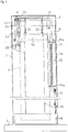
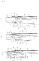
- the numeral 1 is a quadratic prism-shaped device body or case situated on a bed plate 2; closing cover 3 is installed on top of the device body 1.
- a fixed support 4 is mounted inside the upper device body 1; a hanger 6, which is suspended to retain storage sacks 5, is set on the fixed support base 4.
- the hanger 6 is comprised of a bar or the like in the form of a box (top-open rectangle-shaped).
- the base 6a is anchored to a hook (not illustrated) and then mounted on the fixed support base 4.
- the hanger 6 is installed by attaching both arms 6b to the anchor holes 8a of a support member 8 which is fixed to the fixed support base 4 for easy removal.
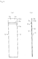
- the top part of the storage sack 5 has an opening 5a.
- the upper end 51a of the front side 51 of the opening is folded forward in a U-shape; the upper end 52a of the rear side 52 extends above of the front side 51; and a pair of locking holes 5b are provided at the upper end of the extended portion.
- a number of storage sacks are suspended and are held by inserting the opposing arms of the hanger 6 into the locking hole 5b of the storage sacks.
- a movable pressure plate 9 is located along a pair of guide bars 10,10 on the rear face of the storage sacks 5; and the pressure plate 9 is urged against the rear face of the storage sacks 5 by a coil spring 10a around each guide bar.
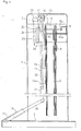
- the guide members 14, 15 are mounted to the front of the fixed support base 4.
- a movable support member 11 having an inverted L-shape (front view) is constrained to move vertically in holes 14b,15b formed on the horizontal arms 14a,15a of the guide members 14,15.
- a roller 12 is provided at the upper end of the movable support member 11 to rotate freely.
- the roller 12 is arranged along with a box type guide rail 13 mounted at the front of the fixed support base 4, to move it vertically.
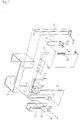
- a foot pedal 16 is provided on the bed plate 2 to lower the movable support member 11. As shown in Figure 4, the foot pedal 16 is mounted on a hinge 17 on the bed plate 2 so as to move vertically.
- a lever 18 is integrally mounted to the pedal 16 and is connected to the lower end of the movable support member 11 through a link 19.
- the numeral 20 denotes a return spring provided to return the movable support member 11.
- the return spring 20 is arranged at a position between a spring bearing 21 and a horizontal arm 14a of the guide member 14 in a contracted condition.
- Said spring bearing is comprised of a clip or similar and is mounted to the movable support member 11.
- a pair of opening levers 22,22 are rotatably provided on the upper central portion of the movable support member 11. Said levers 22,22 enter into the openings 5a of storage sacks 5 to open them. Both ends of said levers 22,22 are integrally connected in a bottom-open rectangle-shape.
- An arm 23 is integrally provided on one end of the levers 22,22 to rotate them.
- a contact plate 24 integral with the guide rail 13 is provided under the arm 23. The contact plate 24 moves to rotate both levers 22,22 in a clockwise direction as seen from Figure 4 by contacting with said arm 23.
- the numeral 25 represents a coil spring set as a tension coil spring between the moving control arm 23 and the spring bearing 26 which is connected vertically to one end of the movable support member 11 so as to be freely rotatable.
- the lower ends of the opening levers 22,22 are urged in a direction towards the storage sacks 5. This is achieved by attaching one end of a helical spring to the movable support member 11 and attaching the other end of the spring to the opening lever 22.
- the helical spring or the like can be arranged around the movable support member 11 close to the opening lever 22.
- the upper part 51a of the storage sack 5 may be prevented from coming away from the lever 22 when it is rotated by a concave area 22b [See Figure 7(c)] formed close to the end of the opening lever 22.
- an umbrella may be inserted into the storage sack 5, between the opening levers 22,22, to store it.
- the sack 5 in which the umbrella is stored can be removed from the hanger 6, by pushing the sack out and down from the device body 1 thus tearing the upper locking holes 5b of the storage sack 5.
- the sack containing an umbrella can easily be removed from the device body 1.
- umbrellas can easily be stored in a storage sack without needing to use a motor or a vacuum pump or the like in order to ensure proper opening of the storage sacks.
- FIG. 8 to Figure 12 Another embodiment will now be described with reference to Figures 8 to 12.
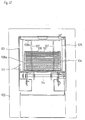
- a number of storage sacks 104 are firstly stored in a box 105; and the box is charged in a device body 101.
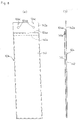
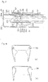
- a storage sack which is used in the present embodiment is shown in Figures 8(a) and 8(b).
- the storage sack 104 comprises a plastic film or the like, and as shown in Figure 8, it is formed in a flat tubular shape.
- the upper part of the storage sack has an opening 104a.
- the upper end 141a of the front side 141 of the opening 104a is folded in a U-shape toward the rear side 142; and the upper end 142a of the rear side 142 extends beyond the front side 141.
- a pair of locking holes 104b are provided in the extended portion.
- the aforementioned box 105 is made of corrugated fibreboard. As shown in Figure 9, it is formed in the shape of a longitudinal rectangular parallelepiped. As shown in Figure 10, a pair of bar-shaped hangers 107, 107 are provided inside the upper part of said box 105 and said hangers 107,107 penetrate the locking holes 104b of the storage sacks 104. The hanger 107 is attached to support plates 108a,108b fixed to the upper inner surface of the box 105. Thus a number of storage sacks 104 can be suspended such that their front sides 141 face the left-hand side as shown in Figure 10.
- a pressure plate (see 109, Figure 12) is arranged on the rear face of the storage sacks 104 to apply pressure to the storage sacks using an elastic means.
- a rubber band 110 is used as the elastic means; both ends of the rubber band 110 being anchored to hooks 181 provided on either side of the supporting plate 108a.
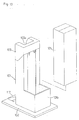
- a panel 151 which is removable along perforations 105a, is provided on the front face of the box 105.
- the box 105 and its contents are transferred and stored before they are used without removing the panel 151.
- the panel 151 is removed along the perforations 105a, the door 106 provided on the rear side of the device body 101 is opened to fit the box 105 into the device body 101.
- a box type fixed support member is integrally provided inside the device body 101 to support the upper part of the box 105 placed in the device body. It is so positioned as to contact the front side of the fixed support member 111 with the front face of the box 105.
- the box 105 containing storage sacks for umbrellas is fitted to the device body 101 from the rear side thereof.
- the box can be fitted from the top of the device body 101 by arranging, for example, for cover 103 to be openable.
- a frame body 101b could form part of the device body in order to locate and retain the box 105 in the frame 101b without all the faces of the box 105 being covered by the device body 101.
- a pair of horizontal opening levers are constructed so as to move and rotate independently.
- a left-hand side tension coil spring 224 is employed between a left-hand side rotation control arm 223 and the guide rail 216; a right-hand side tension coil spring is arranged between a right-hand side rotation control arm 223 and the guide member 212.
- contacting plates 225,225 are integrally provided on the guide rail 216 and guide member 212. The contacting plates cause each opening lever 222 to rotate in the reverse direction towards a storage sack 204 through contact with the rotation control arm 223 when the opening levers 222 move downward together with a movable support member 214.
- tension coil spring is shown as the means of making each opening lever 222,222 rotate towards the storage sacks 204, other helical springs could be used.
- each opening lever 222 can be inserted into the opening 204a by lowering it whilst it is in contact with the front face of the upper rear side 242a of the foremost storage sack 204 even if there is some longitudinal misregistration of the opening 204a in a transverse direction relative to the foremost storage sack 204.
- the foot pedal is pressed until the umbrella and its storage sack are removed from the device body.
- the foot pedal is released after the storage sack is taken out, the device is returned to its original condition by the return spring working to raise the movable support member.
- the device may be so constructed that the foremost storage sack is held open by employing anchoring means to keep the movable support member in its lower position, even when the foot pedal is released until the stored umbrella is taken away from the device.
- anchoring means to keep the movable support member in its lower position, even when the foot pedal is released until the stored umbrella is taken away from the device.
- a plurality of locking grooves 226 may be formed on the movable support member 214 and an anchoring claw 227 which engages with said grooves can be integrally formed on the guide member 213.
- the movable support member 214 When an umbrella is stored in the opening 204a of a storage sack 204 and the umbrella and sack are removed from the device body, the movable support member 214 will be inclined in such a direction as to release the anchoring claw 227 by the opening lever 222. Hence, the anchoring locking groove 226 and anchoring claw 227 are disengaged and the movable support member 214 is automatically returned to its original upper position by the restoring force of the return spring 220.
- Figures 18 to 20 show a further embodiment of the present invention.
- numeral 328 represents a substantially 'C'-shaped member integrally formed from plastic. Umbrellas can be inserted easily and completely due to the shape of this 'C'-shaped member 328. Opening of storage sacks 5 by 'C'-shaped members 328 is shown in Figures 19 and 20, however, a detailed explanation is not given because the states shown in Figure 19 and Figure 20 are almost the same to that in Figures 7(a) to 7(c). Furthermore, the aforementioned embodiment is just an example, therefore structural changes are possible within the scope of the present invention.
- the opening of a storage sack can be opened by operating the opening levers in connection with lowering a movable support member by depressing a foot pedal.
- a wet umbrella may then easily be stored by inserting it into the opening of the storage sack.
- said opening levers when a pair of opening levers are separate so as to move and rotate independently relative to the movable support member, said opening levers can completely enter into and open said opening, although some misregistration of the opening may occur in the longitudinal direction of the storage sack.
Landscapes
- Engineering & Computer Science (AREA)
- Mechanical Engineering (AREA)
- Holders For Apparel And Elements Relating To Apparel (AREA)
- Auxiliary Apparatuses For Manual Packaging Operations (AREA)
- Supplying Of Containers To The Packaging Station (AREA)
- Walking Sticks, Umbrellas, And Fans (AREA)
Claims (5)
- Aufbewahrungsvorrichtung für Regenschirmsäcke, die ein Vorrichtungsgehäuse (1) zur Aufbewahrung einer Vielzahl von Aufbewahrungssäcken (5; 104) mit einer Öffnung in ihrem oberen Teil (5a; 104a) sowie eine Einrichtung (22, 222; 328) zum Öffnen der Öffnung des vordersten der Aufbewahrungssäcke umfaßt, gekennzeichnet durch ein vertikal bewegliches Trägerelement (11; 114; 214), das in dem Vorrichtungsgehäuse angeordnet ist; ein Fußpedal (16; 217), das mit dem beweglichen Trägerelement verbunden ist, um es abzusenken, wenn das Fußpedal getreten wird; sowie Öffnungshebel (22; 222; 328), die schwenkbar an dem Trägerelement angebracht sind und bei Abwärtsbewegung des Trägerelementes (11; 114; 214) in die Öffnung (5a; 104) des vordersten Sacks eingeführt werden und sie anschließend öffnen.
- Aufbewahrungsvorrichtung für Regenschirmsäcke nach Anspruch 1, die eine Vielzahl von Aufbewahrungssäcken (5; 104) in einem Kasten (105) enthält, der in das Vorrichtungsgehäuse (1) eingesetzt ist.
- Aufbewahrungsvorrichtung für Regenschirmsäcke nach Anspruch 2, wobei die Vielzahl von Aufbewahrungssäcken (5; 104) an einer Aufhängevorichtung (107) in dem Kasten aufgehängt ist.
- Aufbewahrungsvorrichtung für Regenschirmsäcke nach Anspruch 1, 2 oder 3, die ein Paar separater Öffnungshebel (22, 222) umfaßt, die sich in bezug auf das bewegliche Trägerelement (11, 114; 214) unabhäng bewegen und drehen; sowie eine Einrichtung (25, 224), die jeden der Öffnungshebel in einer Richtung dreht, in der er in Funktion in Kontakt mit einem in dem Vorrichtungsgehäuse (1) aufbewahrten Aufbewahrungssack (5; 104) kommt.
- Aufbewahrungsvorrichtung für Regenschirmsäcke nach Anspruch 1, 2 oder 3, wobei die Öffnungshebel integral an einem im wesentlichen C-förmigen Element (328) ausgebildet sind.
Applications Claiming Priority (7)
| Application Number | Priority Date | Filing Date | Title |
|---|---|---|---|
| JP4113193 | 1993-06-30 | ||
| JP41131/93U | 1993-06-30 | ||
| JP32107093A JP2777326B2 (ja) | 1993-11-26 | 1993-11-26 | 傘の袋収納装置 |
| JP321070/93 | 1993-11-26 | ||
| JP5321071A JP2813292B2 (ja) | 1993-11-26 | 1993-11-26 | 傘の袋収納装置 |
| JP321071/93 | 1993-11-26 | ||
| PCT/JP1993/001852 WO1995001281A1 (en) | 1993-06-30 | 1993-12-22 | Apparatus for getting an umbrella received into an umbrella cover |
Publications (3)
| Publication Number | Publication Date |
|---|---|
| EP0657357A1 EP0657357A1 (de) | 1995-06-14 |
| EP0657357A4 EP0657357A4 (de) | 1995-11-29 |
| EP0657357B1 true EP0657357B1 (de) | 1998-04-22 |
Family
ID=27290723
Family Applications (1)
| Application Number | Title | Priority Date | Filing Date |
|---|---|---|---|
| EP94903036A Expired - Lifetime EP0657357B1 (de) | 1993-06-30 | 1993-12-22 | Vorrichtung zum einbringen eines schirms in eine hülle |
Country Status (8)
| Country | Link |
|---|---|
| US (1) | US5586683A (de) |
| EP (1) | EP0657357B1 (de) |
| KR (1) | KR0167023B1 (de) |
| CN (3) | CN1096437A (de) |
| DE (1) | DE69318164T2 (de) |
| ES (1) | ES2115925T3 (de) |
| SG (1) | SG47456A1 (de) |
| WO (1) | WO1995001281A1 (de) |
Families Citing this family (6)
| Publication number | Priority date | Publication date | Assignee | Title |
|---|---|---|---|---|
| JPH08276919A (ja) * | 1995-04-04 | 1996-10-22 | Daito Onkyo Kk | 傘袋装着装置 |
| US5551219A (en) * | 1995-10-24 | 1996-09-03 | Wei; Yao-Ming | Package bag expanding device |
| US6766996B1 (en) * | 2001-07-16 | 2004-07-27 | Reid-Ashman Manufacturing, Inc. | Manipulator |
| ATE444902T1 (de) * | 2003-08-27 | 2009-10-15 | Muraharu Seisakusho Kk | Einpackvorrichtung für artikel |
| JP2006151401A (ja) * | 2004-11-25 | 2006-06-15 | Niikura Keiryoki Kk | 傘袋収納装置 |
| CN109288220B (zh) * | 2018-10-31 | 2020-05-29 | 黄海英 | 一种自动雨伞套装置 |
Family Cites Families (15)
| Publication number | Priority date | Publication date | Assignee | Title |
|---|---|---|---|---|
| GB1373175A (en) * | 1972-01-10 | 1974-11-06 | Kristiansen A H | Apparatus for the opening and securing of carrier bags during filling of commodities |
| JPS5315670Y2 (de) * | 1972-09-20 | 1978-04-25 | ||
| SE369373B (de) * | 1972-11-24 | 1974-08-26 | Lundin B Ab | |
| JPS58149914U (ja) * | 1982-03-31 | 1983-10-07 | 老月 太郎 | 傘収納袋 |
| JPS59118711U (ja) * | 1983-01-31 | 1984-08-10 | 株式会社寺岡精工 | 充填包装機における包装用袋の支持構造 |
| JPS60134817A (ja) * | 1983-12-19 | 1985-07-18 | 鷲山精電工業株式会社 | 傘入れ袋の自動開口保持機 |
| JPS62125708A (ja) * | 1985-11-26 | 1987-06-08 | Matsushita Electric Ind Co Ltd | スイツチ回路 |
| FR2592367A1 (fr) * | 1985-12-30 | 1987-07-03 | Castelletta Rene | Dispositif pour distribution de sacs en matiere plastique, en particulier sur des lieux de vente. |
| JPH01124120U (de) * | 1988-02-18 | 1989-08-23 | ||
| US5050743A (en) * | 1989-09-29 | 1991-09-24 | Unisys Corporation | Combined sack and tray system for mail collection |
| JPH0725377B2 (ja) * | 1990-05-21 | 1995-03-22 | 純市 滝本 | 傘収納袋支持装置 |
| JPH06102449B2 (ja) * | 1990-05-21 | 1994-12-14 | 純市 滝本 | 傘収納袋の自動開口装置 |
| JPH0495720U (de) * | 1991-01-10 | 1992-08-19 | ||
| JPH057611U (ja) * | 1991-01-17 | 1993-02-02 | 山田機械工業株式会社 | 傘袋支持装置 |
| US5310102A (en) * | 1992-06-01 | 1994-05-10 | Hougham John K | Apparatus for field sleeving of lettuce and other vegetables |
-
1993
- 1993-12-22 EP EP94903036A patent/EP0657357B1/de not_active Expired - Lifetime
- 1993-12-22 KR KR1019950700466A patent/KR0167023B1/ko not_active Expired - Fee Related
- 1993-12-22 WO PCT/JP1993/001852 patent/WO1995001281A1/ja not_active Ceased
- 1993-12-22 US US08/256,423 patent/US5586683A/en not_active Expired - Fee Related
- 1993-12-22 SG SG1996001815A patent/SG47456A1/en unknown
- 1993-12-22 DE DE69318164T patent/DE69318164T2/de not_active Expired - Fee Related
- 1993-12-22 ES ES94903036T patent/ES2115925T3/es not_active Expired - Lifetime
-
1994
- 1994-02-07 CN CN94101420A patent/CN1096437A/zh active Pending
- 1994-02-07 CN CN94101419A patent/CN1102968A/zh active Pending
- 1994-02-07 CN CN94101417A patent/CN1047564C/zh not_active Expired - Fee Related
Also Published As
| Publication number | Publication date |
|---|---|
| KR950702923A (ko) | 1995-08-23 |
| DE69318164D1 (de) | 1998-05-28 |
| WO1995001281A1 (en) | 1995-01-12 |
| CN1102968A (zh) | 1995-05-31 |
| HK1010453A1 (en) | 1999-06-17 |
| CN1096489A (zh) | 1994-12-21 |
| ES2115925T3 (es) | 1998-07-01 |
| KR0167023B1 (ko) | 1998-12-01 |
| DE69318164T2 (de) | 1998-08-20 |
| EP0657357A4 (de) | 1995-11-29 |
| CN1047564C (zh) | 1999-12-22 |
| US5586683A (en) | 1996-12-24 |
| CN1096437A (zh) | 1994-12-21 |
| SG47456A1 (en) | 1998-04-17 |
| EP0657357A1 (de) | 1995-06-14 |
Similar Documents
| Publication | Publication Date | Title |
|---|---|---|
| EP0626316B1 (de) | Vorrichtung zum einbringen eines gegenstandes in eine hülle | |
| EP0657357B1 (de) | Vorrichtung zum einbringen eines schirms in eine hülle | |
| EP0626315B1 (de) | Vorrichtung zum einbringen eines schirms in eine hülle | |
| JP2562806B2 (ja) | 傘の袋収納装置 | |
| HK1010453B (en) | Apparatus for getting an umbrella received into an umbrella cover | |
| US3777439A (en) | Bag-opening dispenser and method | |
| HK1010452B (en) | Apparatus for getting an umbrella received into an umbrella cover | |
| HK1017574B (en) | Apparatus for getting an article received into a cover | |
| JP2777326B2 (ja) | 傘の袋収納装置 | |
| JP2925906B2 (ja) | 傘の袋収納装置 | |
| JPH07149321A (ja) | 傘の袋収納装置 | |
| JP2925928B2 (ja) | 傘の袋収納装置 | |
| JP2681871B2 (ja) | 傘の袋収納装置およびそれに用いる傘収納袋 | |
| JPH0717528A (ja) | 傘の袋収納装置 | |
| JPS63248610A (ja) | 雨傘袋形成装置 | |
| JPH07291240A (ja) | 傘の袋収納装置 | |
| KR200181075Y1 (ko) | 비닐봉지에 젖은 우산을 투입·자동포장시키는 장치 | |
| JP2820929B2 (ja) | 傘袋収納スタンド | |
| JP4268244B2 (ja) | 葉菜類の袋詰め装置 | |
| JPS5918973Y2 (ja) | 包装用フイルムの加熱切断装置 | |
| CA1300191C (en) | Transportable and collapsable bag carrier | |
| JP2523125Y2 (ja) | 結束機 | |
| US2646890A (en) | Garment hanger | |
| JPH0665204U (ja) | クリーニング済み衣服の立体包装用支持スタンド | |
| JPH08244736A (ja) | 傘袋の自動装着装置および自動取り外し装置 |
Legal Events
| Date | Code | Title | Description |
|---|---|---|---|
| PUAI | Public reference made under article 153(3) epc to a published international application that has entered the european phase |
Free format text: ORIGINAL CODE: 0009012 |
|
| 17P | Request for examination filed |
Effective date: 19950323 |
|
| AK | Designated contracting states |
Kind code of ref document: A1 Designated state(s): DE ES FR GB IT NL |
|
| A4 | Supplementary search report drawn up and despatched | ||
| AK | Designated contracting states |
Kind code of ref document: A4 Designated state(s): DE ES FR GB IT NL |
|
| 17Q | First examination report despatched |
Effective date: 19960229 |
|
| GRAG | Despatch of communication of intention to grant |
Free format text: ORIGINAL CODE: EPIDOS AGRA |
|
| GRAG | Despatch of communication of intention to grant |
Free format text: ORIGINAL CODE: EPIDOS AGRA |
|
| GRAH | Despatch of communication of intention to grant a patent |
Free format text: ORIGINAL CODE: EPIDOS IGRA |
|
| GRAH | Despatch of communication of intention to grant a patent |
Free format text: ORIGINAL CODE: EPIDOS IGRA |
|
| GRAA | (expected) grant |
Free format text: ORIGINAL CODE: 0009210 |
|
| AK | Designated contracting states |
Kind code of ref document: B1 Designated state(s): DE ES FR GB IT NL |
|
| ITF | It: translation for a ep patent filed | ||
| REF | Corresponds to: |
Ref document number: 69318164 Country of ref document: DE Date of ref document: 19980528 |
|
| REG | Reference to a national code |
Ref country code: ES Ref legal event code: FG2A Ref document number: 2115925 Country of ref document: ES Kind code of ref document: T3 |
|
| ET | Fr: translation filed | ||
| PG25 | Lapsed in a contracting state [announced via postgrant information from national office to epo] |
Ref country code: GB Free format text: LAPSE BECAUSE OF NON-PAYMENT OF DUE FEES Effective date: 19981222 |
|
| PLBE | No opposition filed within time limit |
Free format text: ORIGINAL CODE: 0009261 |
|
| STAA | Information on the status of an ep patent application or granted ep patent |
Free format text: STATUS: NO OPPOSITION FILED WITHIN TIME LIMIT |
|
| 26N | No opposition filed | ||
| PG25 | Lapsed in a contracting state [announced via postgrant information from national office to epo] |
Ref country code: NL Free format text: LAPSE BECAUSE OF NON-PAYMENT OF DUE FEES Effective date: 19990701 |
|
| GBPC | Gb: european patent ceased through non-payment of renewal fee |
Effective date: 19981222 |
|
| PG25 | Lapsed in a contracting state [announced via postgrant information from national office to epo] |
Ref country code: FR Free format text: LAPSE BECAUSE OF NON-PAYMENT OF DUE FEES Effective date: 19990831 |
|
| NLV4 | Nl: lapsed or anulled due to non-payment of the annual fee |
Effective date: 19990701 |
|
| REG | Reference to a national code |
Ref country code: FR Ref legal event code: ST |
|
| PG25 | Lapsed in a contracting state [announced via postgrant information from national office to epo] |
Ref country code: DE Free format text: LAPSE BECAUSE OF NON-PAYMENT OF DUE FEES Effective date: 19991001 |
|
| PG25 | Lapsed in a contracting state [announced via postgrant information from national office to epo] |
Ref country code: ES Free format text: LAPSE BECAUSE OF NON-PAYMENT OF DUE FEES Effective date: 19991223 |
|
| REG | Reference to a national code |
Ref country code: ES Ref legal event code: FD2A Effective date: 20000114 |
|
| PG25 | Lapsed in a contracting state [announced via postgrant information from national office to epo] |
Ref country code: IT Free format text: LAPSE BECAUSE OF NON-PAYMENT OF DUE FEES;WARNING: LAPSES OF ITALIAN PATENTS WITH EFFECTIVE DATE BEFORE 2007 MAY HAVE OCCURRED AT ANY TIME BEFORE 2007. THE CORRECT EFFECTIVE DATE MAY BE DIFFERENT FROM THE ONE RECORDED. Effective date: 20051222 |