EP0657725A2 - Rollenträger zur Bestimmung von immanenten Kräften - Google Patents
Rollenträger zur Bestimmung von immanenten Kräften Download PDFInfo
- Publication number
- EP0657725A2 EP0657725A2 EP94118811A EP94118811A EP0657725A2 EP 0657725 A2 EP0657725 A2 EP 0657725A2 EP 94118811 A EP94118811 A EP 94118811A EP 94118811 A EP94118811 A EP 94118811A EP 0657725 A2 EP0657725 A2 EP 0657725A2
- Authority
- EP
- European Patent Office
- Prior art keywords
- support arms
- supply roll
- strain gauges
- computer
- measured
- Prior art date
- Legal status (The legal status is an assumption and is not a legal conclusion. Google has not performed a legal analysis and makes no representation as to the accuracy of the status listed.)
- Granted
Links
Images

Classifications
-
- G—PHYSICS
- G01—MEASURING; TESTING
- G01L—MEASURING FORCE, STRESS, TORQUE, WORK, MECHANICAL POWER, MECHANICAL EFFICIENCY, OR FLUID PRESSURE
- G01L5/00—Apparatus for, or methods of, measuring force, work, mechanical power, or torque, specially adapted for specific purposes
- G01L5/04—Apparatus for, or methods of, measuring force, work, mechanical power, or torque, specially adapted for specific purposes for measuring tension in flexible members, e.g. ropes, cables, wires, threads, belts or bands
- G01L5/10—Apparatus for, or methods of, measuring force, work, mechanical power, or torque, specially adapted for specific purposes for measuring tension in flexible members, e.g. ropes, cables, wires, threads, belts or bands using electrical means
- G01L5/106—Apparatus for, or methods of, measuring force, work, mechanical power, or torque, specially adapted for specific purposes for measuring tension in flexible members, e.g. ropes, cables, wires, threads, belts or bands using electrical means for measuring a reaction force applied on a cantilever beam
-
- B—PERFORMING OPERATIONS; TRANSPORTING
- B65—CONVEYING; PACKING; STORING; HANDLING THIN OR FILAMENTARY MATERIAL
- B65H—HANDLING THIN OR FILAMENTARY MATERIAL, e.g. SHEETS, WEBS, CABLES
- B65H16/00—Unwinding, paying-out webs
- B65H16/005—Dispensers, i.e. machines for unwinding only parts of web roll
-
- B—PERFORMING OPERATIONS; TRANSPORTING
- B65—CONVEYING; PACKING; STORING; HANDLING THIN OR FILAMENTARY MATERIAL
- B65H—HANDLING THIN OR FILAMENTARY MATERIAL, e.g. SHEETS, WEBS, CABLES
- B65H16/00—Unwinding, paying-out webs
- B65H16/02—Supporting web roll
-
- B—PERFORMING OPERATIONS; TRANSPORTING
- B65—CONVEYING; PACKING; STORING; HANDLING THIN OR FILAMENTARY MATERIAL
- B65H—HANDLING THIN OR FILAMENTARY MATERIAL, e.g. SHEETS, WEBS, CABLES
- B65H16/00—Unwinding, paying-out webs
- B65H16/10—Arrangements for effecting positive rotation of web roll
- B65H16/103—Arrangements for effecting positive rotation of web roll in which power is applied to web-roll spindle
-
- B—PERFORMING OPERATIONS; TRANSPORTING
- B65—CONVEYING; PACKING; STORING; HANDLING THIN OR FILAMENTARY MATERIAL
- B65H—HANDLING THIN OR FILAMENTARY MATERIAL, e.g. SHEETS, WEBS, CABLES
- B65H26/00—Warning or safety devices, e.g. automatic fault detectors, stop-motions, for web-advancing mechanisms
-
- G—PHYSICS
- G01—MEASURING; TESTING
- G01B—MEASURING LENGTH, THICKNESS OR SIMILAR LINEAR DIMENSIONS; MEASURING ANGLES; MEASURING AREAS; MEASURING IRREGULARITIES OF SURFACES OR CONTOURS
- G01B21/00—Measuring arrangements or details thereof, where the measuring technique is not covered by the other groups of this subclass, unspecified or not relevant
- G01B21/02—Measuring arrangements or details thereof, where the measuring technique is not covered by the other groups of this subclass, unspecified or not relevant for measuring length, width, or thickness
-
- G—PHYSICS
- G01—MEASURING; TESTING
- G01B—MEASURING LENGTH, THICKNESS OR SIMILAR LINEAR DIMENSIONS; MEASURING ANGLES; MEASURING AREAS; MEASURING IRREGULARITIES OF SURFACES OR CONTOURS
- G01B21/00—Measuring arrangements or details thereof, where the measuring technique is not covered by the other groups of this subclass, unspecified or not relevant
- G01B21/02—Measuring arrangements or details thereof, where the measuring technique is not covered by the other groups of this subclass, unspecified or not relevant for measuring length, width, or thickness
- G01B21/06—Measuring arrangements or details thereof, where the measuring technique is not covered by the other groups of this subclass, unspecified or not relevant for measuring length, width, or thickness specially adapted for measuring length or width of objects while moving
-
- G—PHYSICS
- G01—MEASURING; TESTING
- G01G—WEIGHING
- G01G19/00—Weighing apparatus or methods adapted for special purposes not provided for in the preceding groups
- G01G19/14—Weighing apparatus or methods adapted for special purposes not provided for in the preceding groups for weighing suspended loads
- G01G19/18—Weighing apparatus or methods adapted for special purposes not provided for in the preceding groups for weighing suspended loads having electrical weight-sensitive devices
-
- G—PHYSICS
- G01—MEASURING; TESTING
- G01G—WEIGHING
- G01G3/00—Weighing apparatus characterised by the use of elastically-deformable members, e.g. spring balances
- G01G3/12—Weighing apparatus characterised by the use of elastically-deformable members, e.g. spring balances wherein the weighing element is in the form of a solid body stressed by pressure or tension during weighing
- G01G3/14—Weighing apparatus characterised by the use of elastically-deformable members, e.g. spring balances wherein the weighing element is in the form of a solid body stressed by pressure or tension during weighing measuring variations of electrical resistance
- G01G3/1402—Special supports with preselected places to mount the resistance strain gauges; Mounting of supports
-
- G—PHYSICS
- G01—MEASURING; TESTING
- G01L—MEASURING FORCE, STRESS, TORQUE, WORK, MECHANICAL POWER, MECHANICAL EFFICIENCY, OR FLUID PRESSURE
- G01L5/00—Apparatus for, or methods of, measuring force, work, mechanical power, or torque, specially adapted for specific purposes
- G01L5/04—Apparatus for, or methods of, measuring force, work, mechanical power, or torque, specially adapted for specific purposes for measuring tension in flexible members, e.g. ropes, cables, wires, threads, belts or bands
- G01L5/10—Apparatus for, or methods of, measuring force, work, mechanical power, or torque, specially adapted for specific purposes for measuring tension in flexible members, e.g. ropes, cables, wires, threads, belts or bands using electrical means
-
- G—PHYSICS
- G01—MEASURING; TESTING
- G01L—MEASURING FORCE, STRESS, TORQUE, WORK, MECHANICAL POWER, MECHANICAL EFFICIENCY, OR FLUID PRESSURE
- G01L5/00—Apparatus for, or methods of, measuring force, work, mechanical power, or torque, specially adapted for specific purposes
- G01L5/04—Apparatus for, or methods of, measuring force, work, mechanical power, or torque, specially adapted for specific purposes for measuring tension in flexible members, e.g. ropes, cables, wires, threads, belts or bands
- G01L5/10—Apparatus for, or methods of, measuring force, work, mechanical power, or torque, specially adapted for specific purposes for measuring tension in flexible members, e.g. ropes, cables, wires, threads, belts or bands using electrical means
- G01L5/108—Apparatus for, or methods of, measuring force, work, mechanical power, or torque, specially adapted for specific purposes for measuring tension in flexible members, e.g. ropes, cables, wires, threads, belts or bands using electrical means for measuring a reaction force applied on a single support, e.g. a glider
-
- B—PERFORMING OPERATIONS; TRANSPORTING
- B65—CONVEYING; PACKING; STORING; HANDLING THIN OR FILAMENTARY MATERIAL
- B65H—HANDLING THIN OR FILAMENTARY MATERIAL, e.g. SHEETS, WEBS, CABLES
- B65H2511/00—Dimensions; Position; Numbers; Identification; Occurrences
- B65H2511/10—Size; Dimensions
- B65H2511/12—Width
-
- B—PERFORMING OPERATIONS; TRANSPORTING
- B65—CONVEYING; PACKING; STORING; HANDLING THIN OR FILAMENTARY MATERIAL
- B65H—HANDLING THIN OR FILAMENTARY MATERIAL, e.g. SHEETS, WEBS, CABLES
- B65H2515/00—Physical entities not provided for in groups B65H2511/00 or B65H2513/00
- B65H2515/10—Mass, e.g. mass flow rate; Weight; Inertia
-
- B—PERFORMING OPERATIONS; TRANSPORTING
- B65—CONVEYING; PACKING; STORING; HANDLING THIN OR FILAMENTARY MATERIAL
- B65H—HANDLING THIN OR FILAMENTARY MATERIAL, e.g. SHEETS, WEBS, CABLES
- B65H2515/00—Physical entities not provided for in groups B65H2511/00 or B65H2513/00
- B65H2515/50—Vibrations; Oscillations
-
- B—PERFORMING OPERATIONS; TRANSPORTING
- B65—CONVEYING; PACKING; STORING; HANDLING THIN OR FILAMENTARY MATERIAL
- B65H—HANDLING THIN OR FILAMENTARY MATERIAL, e.g. SHEETS, WEBS, CABLES
- B65H2553/00—Sensing or detecting means
- B65H2553/20—Sensing or detecting means using electric elements
- B65H2553/21—Variable resistances, e.g. rheostats, potentiometers or strain gauges
-
- B—PERFORMING OPERATIONS; TRANSPORTING
- B65—CONVEYING; PACKING; STORING; HANDLING THIN OR FILAMENTARY MATERIAL
- B65H—HANDLING THIN OR FILAMENTARY MATERIAL, e.g. SHEETS, WEBS, CABLES
- B65H2553/00—Sensing or detecting means
- B65H2553/51—Encoders, e.g. linear
-
- B—PERFORMING OPERATIONS; TRANSPORTING
- B65—CONVEYING; PACKING; STORING; HANDLING THIN OR FILAMENTARY MATERIAL
- B65H—HANDLING THIN OR FILAMENTARY MATERIAL, e.g. SHEETS, WEBS, CABLES
- B65H2557/00—Means for control not provided for in groups B65H2551/00 - B65H2555/00
- B65H2557/20—Calculating means; Controlling methods
Definitions
- the invention relates to a method and a device for determining the immanent forces of a supply roll that has been raised in the support arms of a roll carrier.
- DE 28 43 277 C2 has disclosed a circuit arrangement for determining the material web remaining on an unwinding reel, with which the continuous web length of the web material unwound from the unwinding reel is checked and the web length still remaining on the unwinding reel is calculated.
- the invention has for its object to provide a method for determining the intrinsic forces of a supply roll located in a roll carrier and an associated device for performing the method.
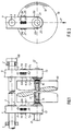
- a feed device in the form of a reel changer is shown in a front view.
- Free ends 12, 13 of the support arms 8, 10 have clamping cones 14, 16 which can be moved towards one another in the axial direction and each engage on the end face in a sleeve 17 on which a web 18, for. B. is wound from paper to a supply roll 19.
- the supply roll 19 can be accelerated either by a known drive acting on its circumferential surface in the circumferential direction or by a drive acting in the center of the supply roll 19 but not shown.
- the supply roll 19 can be braked via the tension cone 14 and the sleeve 17 by means of a brake 21 fixed to the end 12 of the support arm 8 on the side remote from the supply roll.
- the strain gauges 24 to 27 and 61 to 64 can each be glued to the support arms 8, 10 and are located in a region of the support arms 8, 10 near the support spindle.
- the strain gauges 24, 25 are on a right-hand side shown in the illustration in FIG. 2 Side surface 56 of the support arm 8 and the strain gauges 26, 27 applied to a left side surface 57 of the support arm 8.
- the strain gauges 61, 62 are applied to a right side surface 56 of the support arm 10 and the strain gauges 63, 64 to a left side surface 57 of the support arm 10, so that the strain gauges 26, 27 correspond to the direction of rotation of the support spindle 3 according to FIG.
- the support spindle 3 is connected in the vicinity of the side frame 2 to a rotation angle encoder 28 fixed to the frame.
- the roller carriers 4, 6 with the support arms 7 to 10 arranged thereon are arranged on the support spindle 3 so as to be horizontally displaceable in the axial direction in order to accommodate supply rollers 19 of different widths.
- the roller carriers 4, 6 can be rotated together with the support spindle 3, so that the support arms 8, 10 can also assume a different position than in 1 and 2 is shown.
- the support arms 8, 10 can assume a horizontal position, as is required when preparing an adhesive tip, or they can also assume an intermediate position, e.g. B. for receiving a supply roll 19 from a supply roll 19 promoting device.
- a corresponding evaluation circuit is shown in FIG. 3.
- the strain gauges 24 to 27 and 61 to 64 simultaneously correspond to the resistors 24 to 27 and 61 to 64 in a known Wheatstone bridge circuit with amplification.
- the outputs of the bridge circuit are on the one hand via an RC adjustment 29, an amplifier 31, a bandpass 32, and on the other hand a frequency generator 33, a 90 ° phase shifter 34 and a sine-wave converter 36 with a phase-correct demodulator 37, and via a low-pass filter 38 connected to a computer 39.
- the aforementioned elements 29 to 38 can be accommodated in a separate housing and are connected to one another and to the strain gauges 24 to 27 and 61 to 64 by electrical lines (not shown in more detail).
- the computer 39 can be arranged in the machine control center or at another central location.
- a computer 41 is assigned a keyboard 41, via which the computer 39 enters the grammage or the specific weight 42 of the web 18 and the width 43 of the web 18.
- the computer 39 can also be operated via a switch 44 signal 58, which is symbolized by an arrow, can optionally be supplied, which results from a weighing of a second supply roll, not shown, located on the support arms 7, 8 indicated in FIG. 1.
- the technical means required for this correspond to those with which the other measured values 40 fed to the computer 39 via the changeover switch 44 have been determined.
- the changeover switch 44 is actuated by an actuating device 46, e.g. B. actuated by magnetic force.
- the arrangement works as follows:
- the bridge circuit shown in FIG. 3 is connected to voltage.
- a differential voltage is measured, amplified and evaluated between the strain gauges, which, taking into account the angular position of the support arms 8, 10, enables a calculation of the current weight of a supply roll 19.
- the support arms 8, 10 and also the support arms 7, 9 are calibrated according to their rotational angle position.
- the weight of a sleeve 17 receiving the webs 18 is also known. After entering the width 43 and the specific weight 42 or grammage of the web 18 in the computer 39, the average length of a web 18 on a supply roll 19 or a remaining roll can be determined (indirect measurement of the bearing force P via the strain gauges of the support arms). Bearing forces P on the roller carriers (4, 6) the stored supply roll 19 measured in the static state of the supply roll 19. The corresponding signal 40, 58, together with the signals from the input of the width 43 and the specific weight 42 of the material web 18 and the information from the angle encoder 28, produces a value over the length of the the supply roll 19 located material web 18th
- FIG. 4 a longitudinal sectional illustration of a support arm 10 is shown (FIG. 4).
- a shaft 47 which at its first end carries a tension cone 16 for receiving one end of the sleeve 17 of a supply roll 19.
- the shaft 47 is coaxially surrounded by a sliding bush 48 and is against the sliding bush 48 supported at its first end via a known force measuring bearing 49 and at its second end via a ball bearing 51 and is thus rotatably supported in this sliding bush 48.
- the force measuring bearing 49 in which the shaft 47 is mounted, consists of two rings, not shown, namely an inner ring which receives the rolling bearing and an outer ring which is fastened to the sliding bush 48.
- the inner and outer ring are connected by a web. This web is the actual measuring element. If the force measuring bearing 49 is loaded by a bearing force P, the web is z. B. claimed on bend. The bends lead to Strains and compressions on the flanks of the web. The strains and compressions are proportional to the force mentioned and are used to measure the bearing force P.
- the measurement is carried out with four strain gauges in each case analogous to the strain gauges 24 to 27 which are applied on both sides to the flanks of the web of a force measuring bearing 49 (direct measurement of the bearing force P).
- strain gauges are also used, analogously to the strain gauges 61 to 64.
- the second end of the shaft 47 is non-positively and positively connected to a brake 21 fixed to the supporting arm.
- the sliding bush 48 is displaceable in the direction of the axis of rotation 22 of the supply roll 19 (not shown) and is carried in the support arm 10 on the side near the brake by a flange 52 and on the side near the clamping cone also carried by a flange 53, the flanges 52, 53 being non-positive and positive are connected to the support arm 10 at its end 13.
- a slide bearing 59 is arranged in the region of the flanges 52, 53.
- the support arm 8 also has a bearing, as shown in Fig. 4.
- a corresponding evaluation circuit is similar to that according to FIG. 3.
- a possible imbalance of a supply roll 19 which has been raised to the tensioning cones 14, 16 of the roll carriers 4, 6 can by measuring the bearing forces P in the dynamic state during the rotational movement of the supply roll 19 by means of the measured values determined by the transducers 24 to 27 and 61 to 64.
- the measured values are converted into proportional electrical signals 40, 58 by the known evaluation circuit and fed to the computer 39.
- a limit value 45 for the centrifugal force P has been entered into the computer 39 by means of the keyboard 41, when it is exceeded a signal 54 is generated which can automatically reduce the speed of the supply roll 19 or switch off the machine.
- the signal 54 can also be designed as an optical or acoustic signal.
- strain gauges 66, 67; 68, 69 on the side surfaces 71; 72 of the support arms 8; 10 to arrange as well as strain gauges 76, 77; 78, 79 on the side surfaces 73; 74 of the support arms 8; 10 to arrange.
- strain gauges not shown, are applied to the support arms 7, 9, not shown.
- These strain gauges 66 to 69 and 76 to 79 have the same function as the previously mentioned strain gauges 24 to 27 and 61 to 64, which are alternatively arranged on the right and left side surfaces 56, 57 of the support arms 7 to 10.
Landscapes
- Physics & Mathematics (AREA)
- General Physics & Mathematics (AREA)
- Force Measurement Appropriate To Specific Purposes (AREA)
- Controlling Rewinding, Feeding, Winding, Or Abnormalities Of Webs (AREA)
- Unwinding Webs (AREA)
- Paper (AREA)
- Replacement Of Web Rolls (AREA)
Abstract
Description
- Die Erfindung betrifft ein Verfahren und eine Einrichtung zur Bestimmung von immanenten Kräften einer in Tragarmen eines Rollenträgers aufgeachsten Vorratsrolle entsprechend dem Oberbegriff des Patentanspruches 1.
- Durch die DE 28 43 277 C2 ist eine Schaltungsanordnung zum Feststellen der auf einer Abwickelrolle verbleibenden Materialbahn bekanntgeworden, mit welcher die fortlaufende Bahnlänge des von der Abwickelrolle abgewickelten Bahnmaterials überprüft und die noch auf der Abwickelrolle verbliebene Bahnlänge errechnet wird.
- Der Erfindung liegt die Aufgabe zugrunde, ein Verfahren zur Bestimmung der immanenten Kräfte einer in einem Rollenträger befindlichen Vorratsrolle sowie eine dazugehörige Einrichtung zur Durchführung des Verfahrens zu schaffen.
- Diese Aufgabe wird erfindungsgemäß durch die Merkmale des kennzeichnenden Teils der Ansprüche 1 und 6 gelöst.
- Durch die Erfindung werden insbesondere folgende Vorteile erzielt: Infolge der Möglichkeit einer ständigen in-line Gewichtsermittlung in den Tragarmen eines Rollenwechslers kann sowohl nach einer ersten Gewichtsermittlung und nachfolgendem Entfernen von auf dem Transport ggf. beschädigten Warenbahnen das Nettogewicht und somit die Bahnlänge einer Vorratsrolle ermittelt werden als auch eine auf einer Restrolle verbleibende Länge einer Warenbahn, z. B. nach Abschluß einer bestimmten Produktion. Weiterhin ist es nunmehr durch die Erfindung ohne Aufwand möglich, eine Unwucht einer zwischen den Spannkonen befindlichen Vorratsrolle zu signalisieren. Eine Unwucht kann sowohl durch falsches Einspannen zwischen den Spannkonen auftreten als auch durch eine beim Lagern oder beim Transportieren deformierte Vorratsrolle ausgelöst werden. Schließlich ist es auch möglich, mittels der Erfindung zu ermitteln, ob eine nahezu warenbahnlose Restrolle aus den zurückgezogen Konen vollständig entfernt worden ist, so daß eine neue Vorratsrolle aufgenommen werden kann.
- Fig. 1
- die Vorderansicht eines Rollenwechslers in Aufachsstellung mit der erfindungsgemäßen Einrichtung,
- Fig. 2
- eine Seitenansicht nach Fig. 2, jedoch ohne Seitengestell,
- Fig. 3
- eine elektrische Auswerteschaltung für eine Dehnungsmessung,
- Fig. 4
- einen Tragarm nach Fig. 1 mit einer erfindungsgemäßen Einrichtung nach einem zweiten Ausführungsbeispiel.
- In Fig. 1 ist eine Zuführvorrichtung in Form eines Rollenwechslers in einer Vorderansicht dargestellt. Eine in angedeuteten Seitengestellen 1, 2 gelagerte, durch einen nichtdargestellten Antrieb drehbare Tragspindel 3 nimmt zwei parallel zueinander verlaufende mit der Tragspindel 3 formschlüssig verbundene Tragarmträgerteile, 4, 6 auf, die doppelarmige Hebel mit jeweils zwei Tragarmen 7, 8 und 9, 10 tragen, von denen jedoch in den Zeichnungen nur die Tragarme 8, 10 vollständig dargestellt sind. Freie Enden 12, 13 der Tragarme 8, 10 weisen in axialer Richtung aufeinander zu bewegbare Spannkonen 14, 16 auf, die jeweils stirnseitig in eine Hülse 17 eingreifen, auf welcher eine Warenbahn 18, z. B. aus Papier zu einer Vorratsrolle 19 aufgewickelt ist. Die Vorratsrolle 19 kann entweder über einen bekannten, auf ihre Mantelfläche in Umfangsrichtung wirkenden, oder einen im Zentrum der Vorratsrolle 19 angreifenden, jedoch nichtdargestellten Antrieb beschleunigt werden. Mittels einer am Ende 12 des Tragarmes 8 auf der vorratsrollenfernen Seite angeflanschten tragarmfesten Bremse 21, kann die Vorratsrolle 19 über den Spannkonus 14 und die Hülse 17 abgebremst werden. An rechten und linken Seitenflächen 56, 57 der Tragarme 8, 10, sind bekannte Dehnungsmeßstreifen 24, 25, 26, 27 sowie 61, 62, 63, 64 aufgebracht, von denen die Dehnungsmeßstreifen 63, 64 jedoch nicht in der Zeichnung dargestellt sind. Die Dehnungsmeßstreifen 24 bis 27 sowie 61 bis 64 können jeweils auf den Tragarmen 8, 10 aufgeklebt sein und befinden sich in einem tragspindelnahen Bereich der Tragarme 8, 10. Dabei sind die Dehnungsmeßstreifen 24, 25 auf einer in der Darstellung nach Fig. 2 gezeigten rechten Seitenfläche 56 des Tragarmes 8 und die Dehnungsmeßstreifen 26, 27 auf einer linken Seitenfläche 57 des Tragarmes 8 aufgebracht. In gleicher Weise sind die Dehnungsmeßstreifen 61, 62 auf einer rechten Seitenfläche 56 des Tragarmes 10 und die Dehnungsmeßstreifen 63, 64 auf einer linken Seitenfläche 57 des Tragarmes 10 aufgebracht, so daß entsprechend der Drehrichtung der Tragspindel 3 nach Fig. 2 die Dehnungsneßstreifen 26, 27; 63, 64 in eine Drehrichtung im Uhrzeigersinn weisen und die Dehnungsmeßstreifen 24, 25; 61, 62 in eine Drehrichtung im Gegenuhrzeigersinn weisen. Somit wird in einem Bereich gemessen, in welchem sich die Materialverformung der Tragarme 8, 10 proportional zum Gewicht bzw. zur Krafteinwirkung verhält. Die Tragspindel 3 ist in der Nähe des Seitengestells 2 mit einem gestellfesten Drehwinkelgeber 28 verbunden. Die Rollenträger 4, 6 mit den daran angeordneten Tragarmen 7 bis 10 sind auf der Tragspindel 3 in axialer Richtung horizontal verschiebbar angeordnet, um Vorratsrollen 19 verschiedener Breite aufzunehmen. Die Rollenträger 4, 6 sind zusammen mit der Tragspindel 3 verdrehbar, so daß die Tragarme 8, 10 auch eine andere Position einnehmen können, als in Fig. 1 und 2 dargestellt ist. Z. B. können die Tragarme 8, 10 eine waagerechte Position einnehmen, wie dies bei einer Vorbereitung einer Klebespitze erforderlich ist oder sie können auch eine dazwischenliegende Position einnehmen, z. B. zur Aufnahme einer Vorratsrolle 19 von einer die Vorratsrolle 19 fördernden Einrichtung. In Fig. 3 ist eine entsprechende Auswerteschaltung gezeigt. Die Dehnungsmeßstreifen 24 bis 27 sowie 61 bis 64 entsprechen gleichzeitig den Widerständen 24 bis 27 sowie 61 bis 64 in einer bekannten Wheatstone'schen Brückenschaltung mit Nachverstärkung. Die Ausgänge der Brückenschaltung sind einerseits über einen RC - Abgleich 29, einen Verstärker 31, einen Bandpaß 32, bzw. andererseits einen Frequenzgenerator 33, einen 90°-Phasenschieber 34 und einen Sinus - Rechteckwandler 36 mit einem phasenrichtigen Demodulator 37, und über einen Tiefpaß 38 mit einem Rechner 39 verbunden. Daraus resultiert ein Signal 40. Die vorgenannten Elemente 29 bis 38 können in einem gesonderten Gehäuse untergebracht sein und sind untereinander sowie mit den Dehnungsmeßstreifen 24 bis 27 sowie 61 bis 64 durch nicht näher dargestellte elektrische Leitungen verbunden. Der Rechner 39 kann im Maschinenleitstand oder an einer anderen zentralen Stelle angeordnet sein. Dem Rechner 39 ist eine Tastatur 41 zugeordnet, über welche dem Rechner 39 die Grammatur bzw. das spezifische Gewicht 42 der Warenbahn 18 sowie die Breite 43 der Warenbahn 18 eingegeben wird. Weiterhin können den Rechner 39 über einen Umschalter 44 auch wahlweise solche durch einen Pfeil symbolisiertes Signal 58 zugeführt werden, das aus einer Wägung einer nichtdargestellten, an den in Fig. 1 angedeuteten Tragarmen 7, 8 befindlichen zweiten Vorratsrolle resultiert. Die dafür erforderlichen technischen Mittel entsprechen denen, mit welchen die anderen, dem Rechner 39 über den Umschalter 44 zugeführten Meßwerte 40 ermittelt worden sind. Der Umschalter 44 ist durch eine über die Tastatur 41 zu betätigende Stelleinrichtung 46, z. B. mittels Magnetkraft, betätigbar. Die Anordnung arbeitet wie folgt: Die in Fig. 3 gezeigte Brückenschaltung wird an Spannung gelegt. Durch Deformation der Dehnungsmeßstreifen entsprechend der jeweiligen Drehwinkelstellung der Tragarme 8, 10 wird zwischen den Dehnungsmeßstreifen eine Differenzspannung gemessen, verstärkt und ausgewertet, welche unter Berücksichtigung der Winkelstellung der Tragarme 8, 10 eine Berechnung des derzeitigen Gewichtes einer Vorratsrolle 19 ermöglicht. Dabei sind die Tragarme 8, 10 sowie ebenso die Tragarme 7, 9 entsprechend ihrer Drehwinkelstellung geeicht. Das Gewicht einer die Warenbahnen 18 aufnehmenden Hülse 17 ist ebenfalls bekannt. Nach Eingabe der Breite 43 sowie des spezifischen Gewichtes 42 bzw. Grammatur der Warenbahn 18 in den Rechner 39 ist die durchschnittliche Länge einer Warenbahn 18 auf einer Vorratsrolle 19 oder einer Restrolle ermittelbar (indirekte Messung der Lagerkraft P über die Dehnungsmeßstreifen der Tragarme).
Dabei werden Lagerkräfte P der auf den Rollenträgern (4, 6) aufgeachsten Vorratsrolle 19 in statischen Zustand der Vorratsrolle 19 gemessen Das entsprechende Signal 40, 58 erzeugt zusammen mit den Signalen aus der Eingabe der Breite 43 sowie des spezifischen Gewichtes 42 der Materialbahn 18 sowie der Angaben des Drehwinkelgebers 28 einen Wert über die Länge der auf der Vorratsrolle 19 befindlichen Materialbahn 18. - Bei einem zweiten Ausführungsbeispiel einer erfindungsgemäßen Anordnung in einem Tragarm 10 ist eine Längsschnittdarstellung eines Tragarmes 10 dargestellt (Fig. 4). Am Ende 13 des Tragarmes 10 befindet sich eine Welle 47, die an ihrem ersten Ende einen Spannkonus 16 trägt zur Aufnahme des einen Endes der Hülse 17 einer Vorratsrolle 19. Die Welle 47 ist koaxial von einer Gleitbuchse 48 umgeben und ist gegen die Gleitbuchse 48 an ihrem ersten Ende über ein bekanntes Kraftmeßlager 49 und an ihrem zweiten Ende über ein Kugellager 51 abgestützt und ist somit drehbar in dieser Gleitbuchse 48 gelagert. Das Kraftmeßlager 49, in welchem die Welle 47 gelagert ist, besteht aus zwei nicht näher dargestellten Ringen, nämlich einem inneren Ring, der das Wälzlager aufnimmt, und einem äußeren Ring, der an der Gleitbuchse 48 befestigt ist. Innerer und äußerer Ring sind durch einen Steg miteinander verbunden. Dieser Steg ist das eigentliche Meßglied. Wird das Kraftmeßlager 49 durch eine Lagerkraft P belastet, so wird der Steg entsprechend seiner Drehwinkelstellung z. B. auf Biegung beansprucht. Die Biegungen führen zu Dehnungen und Stauchungen an den Flanken des Steges. Die Dehnungen und Stauchungen sind der genannten Kraft proportional und werden zur Messung der Lagerkraft P benutzt. Die Messung erfolgt mit jeweils vier Dehnungsmeßstreifen analog den Dehnungsmeßstreifen 24 bis 27, die beidseitig auf den Flanken des genannten Steges eines Kraftmeßlagers 49 aufgebracht sind (direkte Messung der Lagerkraft P). In einem zweiten, nichtdargestellten Kraftmeßlager 50 sind ebenfalls vier Dehnungsmeßstreifen, analog den Dehnungsmeßstreifen 61 bis 64 eingesetzt. Das zweite Ende der Welle 47 ist Kraft- und formschlüssig mit einer tragarmfesten Bremse 21 verbunden. Die Gleitbuchse 48 ist in Richtung der Rotationsachse 22 der nichtdargestellten Vorratsrolle 19 verschiebbar und wird dabei im Tragarm 10 an der bremsnahen Seite von einem Flansch 52 und an der spannkonusnahen Seite ebenfalls von einem Flansch 53 getragen, wobei die Flansche 52, 53 kraft- und formschlüssig mit dem Tragarm 10 an dessen Ende 13 verbunden sind. Zwischen der Gleitbuchse 48 und den die Gleitbuchse 48 beidseitig tragenden und mit einer kreisrunden Öffnung versehenen Flanschen 52, 53 ist im Bereich der Flanschen 52, 53 jeweils ein Gleitlager 59 angeordnet. Der Tragarm 8 weist ebenso eine Lagerung auf, wie in Fig. 4 dargestellt. Eine entsprechende Auswerteschaltung gleicht derjenigen nach Fig. 3.
- Eine mögliche Unwucht einer auf die Spannkonen 14, 16 der Rollenträger 4, 6 aufgeachsten Vorratsrolle 19 kann durch die Messung der Lagerkräfte P im dynamischen Zustand beim Drehbewegen der Vorratsrolle 19 mittels der von den Meßwertaufnehmern 24 bis 27 und 61 bis 64 ermittelten Meßwerte festgestellt werden. Dabei werden die Meßwerte durch die bekannte Auswerteschaltung in proportionale elektrische Signale 40, 58 umgewandelt und dem Rechner 39 zugeführt. Dem Rechner 39 ist mittels der Tastatur 41 ein Grenzwert 45 für die Zentrifugalkraft P eingegeben worden, bei dessen Überschreitung ein Signal 54 erzeugt wird, welches selbsttätig zum Reduzieren der Drehzahl der Vorratsrolle 19 oder zum Abschalten der Maschine führen kann. Das Signal 54 kann auch als optisches oder akustisches Signal ausgebildet sein.
- Es ist weiterhin möglich, Dehnungsmeßstreifen 66, 67; 68, 69 auf den vorratsrollennahen Seitenflächen 71; 72 der Tragarme 8; 10 anzuordnen sowie auch Dehnungsmeßstreifen 76, 77; 78, 79 auf den vorratsrollenfernen Seitenflächen 73; 74 der Tragarme 8; 10 anzuordnen. In analoger weise sind nichtdargestellte Dehnungsmeßstreifen auf den nichtdargestellten Tragarmen 7, 9 aufgebracht. Diese Dehnungsmeßstreifen 66 bis 69 sowie 76 bis 79 haben die gleiche Funktion wie die bereits vorher erwähnten Dehnungsmeßstreifen 24 bis 27 und 61 bis 64, die alternativ auf den rechten und linken Seitenflächen 56, 57 der Tragarme 7 bis 10 angeordnet sind.
-
- 1
- Seitengestell
- 2
- Seitengestell
- 3
- Tragspindel
- 4
- Tragarmlagerteil
- 5
- -
- 6
- Tragarmlagerteil
- 7
- Tragarm (4)
- 8
- Tragarm (4)
- 9
- Tragarm (6)
- 10
- Tragarm (6)
- 11
- -
- 12
- Ende (8)
- 13
- Ende (10)
- 14
- Spannkonus (8)
- 15
- -
- 16
- Spannkonus (10)
- 17
- Hülse
- 18
- Warenbahn
- 19
- Vorratsrolle
- 20
- -
- 21
- Bremse
- 22
- Rotationsachse (19)
- 23
- -
- 24
- Dehnungsmeßstreifen (8)
- 25
- Dehnungsmeßstreifen (8)
- 26
- Dehnungsmeßstreifen (8)
- 27
- Dehnungsmeßstreifen (8)
- 28
- Drehwinkelgeber
- 29
- RC - Abgleich
- 30
- -
- 31
- Verstärker
- 32
- Bandpaß
- 33
- Frequenzgenerator
- 34
- 90°-Phasenschieber
- 35
- -
- 36
- Sinus-Rechteckwandler
- 37
- Demodulator
- 38
- Tiefpaß
- 39
- Rechner
- 40
- Signal
- 41
- Tastatur
- 42
- Gewicht, spezifisches (18)
- 43
- Breite (18)
- 44
- Umschalter (28)
- 45
- Grenzwert Zentrifugalkraft
- 46
- Stelleinrichtung (44)
- 47
- Welle (8)
- 48
- Gleitbuchse (8)
- 49
- Kraftmeßlager (48)
- 50
- Kraftmeßlager
- 51
- Kugellager (48)
- 52
- Flansch
- 53
- Flansch
- 54
- Signal
- 55
- -
- 56
- Seitenfläche, rechte (8, 10; 7, 9)
- 57
- Seitenfläche, linke (8, 10; 7, 9)
- 58
- Signal
- 59
- Gleitlager
- 60
- -
- 61
- Dehnungsmeßstreifen (10)
- 62
- Dehnungsmeßstreifen (10)
- 63
- Dehnungsmeßstreifen (10)
- 64
- Dehnungsmeßstreifen (10)
- 65
- -
- 66
- Dehnungsmeßstreifen (8)
- 67
- Dehnungsmeßstreifen (8)
- 68
- Dehnungsmeßstreifen (10)
- 69
- Dehnungsmeßstreifen (10)
- 70
- -
- 71
- Seitenfläche, vorratsrollennah (8)
- 72
- Seitenfläche, vorratsrollennah (10)
- 73
- Seitenfläche, vorratsrollenfern (8)
- 74
- Seitenfläche, vorratsrollenfern (10)
- 75
- -
- 76
- Dehnungsmeßstreifen (8)
- 77
- Dehnungsmeßstreifen (8)
- 78
- Dehnungsmeßstreifen (10)
- 79
- Dehnungsmeßstreifen (10)
- P
- Lagerkraft, Gewicht
Claims (11)
- Verfahren zur Bestimmung von immanenten Kräften einer in Tragarmen (7, 9; 8, 10) eines Rollenträgers (4, 6) aufgeachsten Vorratsrolle (19), dadurch gekennzeichnet, daß die Lagerkräfte (P) der auf den Tragarmen (7, 9; 8, 10) aufgeachsten Vorratsrolle (19) gemessen werden.
- Verfahren nach Anspruch 1, dadurch gekennzeichnet, daß die Lagerkräfte (P) der auf den Tragarmen (7, 9; 8, 10) aufgeachsten Vorratsrolle (19) gemessen werden.
- Verfahren nach Anspruch 1, dadurch gekennzeichnet, daß die Lagerkräfte (P) der auf den Tragarmen (7, 9; 8, 10) aufgeachsten Vorratsrolle (19) in dynamischem Zustand der Vorratsrolle (19) gemessen werden.
- Verfahren nach den Ansprüchen 1 und 2, dadurch gekennzeichnet, daß das Gewicht (P) der Vorratsrolle (19) in stationärem Zustand durch eine Anzahl von auf den Tragarmen (7, 9; 8, 10) angeordneten Meßwertaufnehmern (24, 25, 26, 27; 61, 62, 63, 64; 66, 67, 68, 69; 76, 77, 78, 79; 49, 50) erfolgt, indem die von den Meßwertaufnehmern (24, 25, 26, 27; 61, 62, 63, 64; 66, 67, 68, 69; 76, 77, 78, 79; 49, 50) aufgenommenen Meßwerte in proportionale elektrische Signale (40, 58) umgewandelt und einem Rechner (39) zugeführt werden, daß der Rechner (39) nachfolgend nach Eingabe (41) der Breite (43) sowie des spezifischen Gewichtes (42) der Materialbahn (18) sowie einer mittels einem Drehwinkelgeber (28) gemessenen Winkellage der Tragarme (7, 9; 8, 10) die Länge der Materialbahn (18) ermittelt.
- Verfahren nach den Ansprüchen 1 und 3, dadurch gekennzeichnet, daß die Messung der Lagerkräfte (P) in dynamischen Zustand beim Drehbewegen der Vorratsrolle (19) mittels einer Anzahl von auf Tragarmen (7, 9; 8, 10) angeordneten Meßwertaufnehmern (24, 25, 26, 27; 61, 62, 63, 64; 66, 67, 68, 69; 76, 77, 78, 79; 49, 50) erfolgt die in proportionale elektrische Signale (40, 58) umgewandelt und einem Rechner (39) zugeführt werden, daß anschließend beim Überschreiten eines voreingestellten Wertes einer Zentrifugalkraft ein Signal (54) abgegeben wird.
- Einrichtung zur Durchführung des Verfahrens nach Anspruch 1 bis 5, dadurch gekennzeichnet, daß die Meßwertaufnehmer (24, 25, 26, 27; 61, 62, 63, 64) an freien Enden (12, 13) der Tragarme (7, 9; 8, 10) des Rollenträgers (4, 6) angeordnet sind und über eine an sich bekannte Auswerteschaltung (29, 31, 32, 33, 34, 36, 37, 38) mit dem Rechner (39) verbunden sind.
- Einrichtung nach Anspruch 6, dadurch gekennzeichnet, daß die Meßwertaufnehmer (24, 25, 26, 27; 61, 62, 63, 64; 66, 67, 68, 69; 76, 77, 78, 79; 49, 50) als Dehnungsmeßstreifen (24, 25, 26, 27; 61, 62, 63, 64; 66, 67, 68, 69, 76, 77, 78, 79; 49, 50) ausgebildet sind.
- Einrichtung nach den Ansprüchen 6 und 7, dadurch gekennzeichnet, daß die Dehnungsmeßstreifen (24, 25, 26, 27; 61, 62, 63, 64) auf rechten und linken Seitenflächen (56, 57) der Tragarme (7, 9; 8, 10) angeordnet sind.
- Einrichtung nach den Ansprüchen 6 und 7, dadurch gekennzeichnet, daß die Dehnungsmeßstreifen (66, 67, 68, 69; 76, 77, 78, 79) auf solchen der Vorratsrolle (19) zugewandten und abgewandten Seitenflächen (71, 72; 73, 74) der Tragarme (7, 9; 8, 10) angeordnet sind.
- Einrichtung nach Anspruch 6, dadurch gekennzeichnet, daß die Meßwertaufnehmer (49; 50) als Kraftmeßlager (49; 50) ausgebildet sind.
- Einrichtung nach den Ansprüchen 6 und 10, dadurch gekennzeichnet, daß die Kraftmeßlager (49; 50) unmittelbar an den die Vorratsrolle (19) beidseitig aufnehmenden Spannkonen (14, 16) angeordnet sind.
Priority Applications (1)
| Application Number | Priority Date | Filing Date | Title |
|---|---|---|---|
| EP98113079A EP0886134B1 (de) | 1993-12-08 | 1994-11-30 | Rollenträger |
Applications Claiming Priority (2)
| Application Number | Priority Date | Filing Date | Title |
|---|---|---|---|
| DE4341800 | 1993-12-08 | ||
| DE4341800A DE4341800C2 (de) | 1993-12-08 | 1993-12-08 | Rollenträger |
Related Child Applications (1)
| Application Number | Title | Priority Date | Filing Date |
|---|---|---|---|
| EP98113079A Division EP0886134B1 (de) | 1993-12-08 | 1994-11-30 | Rollenträger |
Publications (3)
| Publication Number | Publication Date |
|---|---|
| EP0657725A2 true EP0657725A2 (de) | 1995-06-14 |
| EP0657725A3 EP0657725A3 (de) | 1996-01-10 |
| EP0657725B1 EP0657725B1 (de) | 1999-05-12 |
Family
ID=6504458
Family Applications (2)
| Application Number | Title | Priority Date | Filing Date |
|---|---|---|---|
| EP98113079A Expired - Lifetime EP0886134B1 (de) | 1993-12-08 | 1994-11-30 | Rollenträger |
| EP94118811A Expired - Lifetime EP0657725B1 (de) | 1993-12-08 | 1994-11-30 | Rollenträger zur Bestimmung von immanenten Kräften |
Family Applications Before (1)
| Application Number | Title | Priority Date | Filing Date |
|---|---|---|---|
| EP98113079A Expired - Lifetime EP0886134B1 (de) | 1993-12-08 | 1994-11-30 | Rollenträger |
Country Status (4)
| Country | Link |
|---|---|
| US (1) | US5497659A (de) |
| EP (2) | EP0886134B1 (de) |
| JP (1) | JP2647353B2 (de) |
| DE (3) | DE4341800C2 (de) |
Cited By (1)
| Publication number | Priority date | Publication date | Assignee | Title |
|---|---|---|---|---|
| DE102005002030A1 (de) * | 2005-01-15 | 2006-09-14 | Koenig & Bauer Ag | Rollenwechsel zur Durchführung eines fliegenden Rollenwechsels |
Families Citing this family (11)
| Publication number | Priority date | Publication date | Assignee | Title |
|---|---|---|---|---|
| DE102004021627B3 (de) * | 2004-05-03 | 2005-08-18 | Koenig & Bauer Ag | Rollenträger zur Lagerung einer aufgeachsten Vorratsrolle |
| DE102005004559A1 (de) * | 2005-02-01 | 2006-08-10 | Koenig & Bauer Ag | Rollenwechsler mit zumindest zwei schwenkbar gelagerten Tragarmen und ein Verfahren zum Betrieb eines Rollenwechslers |
| NL1031496C2 (nl) * | 2006-04-03 | 2007-10-05 | Multifoil Bv | Productrol en indicatiemiddelen. |
| DE102009047776B4 (de) * | 2009-09-30 | 2012-04-26 | Eastman Kodak Co. | Verfahren und Vorrichtung zum Messen einer Laufrichtung einer Substratbahn |
| DE102010042520B4 (de) * | 2010-10-15 | 2014-07-31 | Koenig & Bauer Aktiengesellschaft | Verfahren zum Verbinden einer ersten Materialbahn mit einer zweiten Materialbahn |
| CN102506688B (zh) * | 2011-10-24 | 2014-06-25 | 浙江大学 | 一种电阻应变式厚度测量装置及其测量方法 |
| US9024212B2 (en) * | 2013-05-09 | 2015-05-05 | Hyer Industries, Inc. | Load sensing system with flexure plate |
| DE102014018781B3 (de) * | 2014-12-19 | 2016-02-11 | Rainhard Nordbrock | Kraftmesseinrichtung |
| US10150260B2 (en) * | 2016-03-08 | 2018-12-11 | General Electric Company | Method and apparatus for dispensing refrigerated fiber prepreg rolls |
| US10852667B2 (en) | 2017-01-26 | 2020-12-01 | Hp Indigo B.V. | Altering the operation of printing devices having engageable components |
| DE102023200403A1 (de) * | 2023-01-19 | 2024-07-25 | Wafios Aktiengesellschaft | Vorrichtung zum Zuführen eines langgestreckten Werkstücks zu einer Umformmaschine |
Family Cites Families (27)
| Publication number | Priority date | Publication date | Assignee | Title |
|---|---|---|---|---|
| NL243307A (de) * | 1958-09-18 | |||
| US3330154A (en) * | 1965-01-12 | 1967-07-11 | Sigma Systems Corp | Apparatus for measuring the resultant load on a stationary shaft |
| US3724733A (en) * | 1972-02-03 | 1973-04-03 | Harris Intertype Corp | Web infeed mechanism |
| DE2510913A1 (de) * | 1975-03-13 | 1976-09-30 | Maschf Augsburg Nuernberg Ag | Lagerung von zur papierbahnzugmessung dienenden walzen in rotationsdruckmaschinen |
| US4151403A (en) * | 1977-10-05 | 1979-04-24 | Molins Machine Company, Inc. | Control system for an unwinding roll |
| GB2119936B (en) * | 1979-03-30 | 1984-05-16 | Cleveland Machine Controls | Force sensing device |
| US4260034A (en) * | 1979-07-12 | 1981-04-07 | Randolph Jr George J J | Conveyor scale |
| US4335439A (en) * | 1980-04-25 | 1982-06-15 | St Denis Andrew R | Weight monitoring device for strip metal stock |
| JPS61130842A (ja) * | 1984-11-29 | 1986-06-18 | Shimadzu Corp | 動釣合試験機 |
| US4970895A (en) * | 1985-05-02 | 1990-11-20 | Measurex Corporation | System and method for the determination of certain physical characteristics of sheet materials. |
| JPH0757443B2 (ja) * | 1985-10-21 | 1995-06-21 | 株式会社アマダ | 材料切断装置 |
| US4674310A (en) * | 1986-01-14 | 1987-06-23 | Wean United Rolling Mills, Inc. | Strip tension profile apparatus and associated method |
| DE3614436A1 (de) * | 1986-04-29 | 1987-11-05 | Jagenberg Ag | Messeinrichtung fuer die druckzonenbreite und/oder flaechenpressung zwischen einem wickel einer materialbahn und einer gegen den wickel gedrueckten walze und verfahren zum wickeln einer materialbahn |
| US4691579A (en) * | 1986-06-03 | 1987-09-08 | Ekola Kenneth E | Tension transducer |
| DE3627382A1 (de) * | 1986-08-12 | 1988-02-18 | Siemens Ag | Messanordnung zum erfassen von kraeften und momenten |
| US4699606A (en) * | 1986-08-18 | 1987-10-13 | Celanese Corporation | Apparatus for detecting and/or controlling tension of a moving web, for example, a filamentary tow utilized in the production of cigarette filters |
| DE3731214A1 (de) * | 1987-09-17 | 1989-03-30 | Koenig & Bauer Ag | Vorrichtung fuer das gesteuerte zufuehren von bandmaterial zu druckmaschinen, sowie ein verfahren und eine vorrichtung zur durchfuehrung des verfahrens zur regelung eines entsprechenden steuersignals |
| JP2781577B2 (ja) * | 1988-12-28 | 1998-07-30 | 株式会社日立製作所 | 動的遠心力載荷実験装置 |
| JPH03115822A (ja) * | 1989-09-29 | 1991-05-16 | Toppan Printing Co Ltd | ロールプレス装置 |
| JPH0722771B2 (ja) * | 1990-03-08 | 1995-03-15 | 住友金属工業株式会社 | 分塊圧延機の圧延荷重測定装置 |
| JP2966040B2 (ja) * | 1990-05-18 | 1999-10-25 | 日本トムソン株式会社 | 遠心荷重軸受試験機 |
| DE4127631C2 (de) * | 1990-10-01 | 2001-07-12 | Volkswagen Ag | Einrichtung zur zumindest qualitativen Ermittlung der Zugkraft eines seil- oder bandförmigen Meßobjektes |
| US5138878A (en) * | 1990-12-28 | 1992-08-18 | Measurex Corporation | Fiber orientation sensor |
| JPH0552640A (ja) * | 1991-08-22 | 1993-03-02 | Toppan Printing Co Ltd | フイルム長管理装置 |
| JPH07280B2 (ja) * | 1991-10-14 | 1995-01-11 | 株式会社森田油圧機製作所 | 素材切断方法と装置 |
| US5365796A (en) * | 1992-09-18 | 1994-11-22 | Rockwell International Corporation | Device for measuring the tension on a web of a printing press |
| DE9212928U1 (de) * | 1992-09-25 | 1992-11-26 | BASF Magnetics GmbH, 6800 Mannheim | Bandzug-Meßwalze |
-
1993
- 1993-12-08 DE DE4341800A patent/DE4341800C2/de not_active Expired - Fee Related
-
1994
- 1994-11-30 DE DE59408245T patent/DE59408245D1/de not_active Expired - Fee Related
- 1994-11-30 EP EP98113079A patent/EP0886134B1/de not_active Expired - Lifetime
- 1994-11-30 DE DE59410032T patent/DE59410032D1/de not_active Expired - Fee Related
- 1994-11-30 EP EP94118811A patent/EP0657725B1/de not_active Expired - Lifetime
- 1994-12-08 US US08/354,757 patent/US5497659A/en not_active Expired - Fee Related
- 1994-12-08 JP JP6305221A patent/JP2647353B2/ja not_active Expired - Lifetime
Cited By (2)
| Publication number | Priority date | Publication date | Assignee | Title |
|---|---|---|---|---|
| DE102005002030A1 (de) * | 2005-01-15 | 2006-09-14 | Koenig & Bauer Ag | Rollenwechsel zur Durchführung eines fliegenden Rollenwechsels |
| DE102005002030B4 (de) * | 2005-01-15 | 2007-08-30 | Koenig & Bauer Aktiengesellschaft | Rollenwechsler zur Zuführung einer Materialbahn |
Also Published As
| Publication number | Publication date |
|---|---|
| EP0886134B1 (de) | 2002-01-02 |
| EP0657725A3 (de) | 1996-01-10 |
| EP0886134A3 (de) | 2000-05-31 |
| DE4341800A1 (de) | 1995-06-14 |
| DE59408245D1 (de) | 1999-06-17 |
| JP2647353B2 (ja) | 1997-08-27 |
| US5497659A (en) | 1996-03-12 |
| EP0657725B1 (de) | 1999-05-12 |
| DE59410032D1 (de) | 2002-02-28 |
| JPH07209107A (ja) | 1995-08-11 |
| EP0886134A2 (de) | 1998-12-23 |
| DE4341800C2 (de) | 2000-02-03 |
Similar Documents
| Publication | Publication Date | Title |
|---|---|---|
| DE4341800C2 (de) | Rollenträger | |
| EP1260470B1 (de) | Verfahren und Vorrichtung zur aktiven Schwingungsdämpfung bei Wickelmaschinen | |
| DE3539980A1 (de) | Verfahren zur steuerung eines papierbahnaufrollers | |
| EP0881181B1 (de) | Abrollstation zum kontinuierlichen Abwickeln einer Materialbahn | |
| DE3416261A1 (de) | Auswuchtgeraet fuer raeder mit luftreifen | |
| EP1108204A1 (de) | Unwuchtmessvorrichtungen mit mindestens einer virtuellen lagerstelle | |
| DE19909162A1 (de) | Verfahren zur Verringerung von durch eine Radeinheit eines Fahrzeuges hervorgerufenen Vibrationen und Einrichtung hierzu | |
| DE854834T1 (de) | Zentrumtreibungsgerät für eines papierwicklersystem | |
| DE3736696C2 (de) | ||
| DE19851483C2 (de) | Verfahren zum Betreiben einer Rollenwickeleinrichtung und Rollenwickeleinrichtung | |
| DE2005105C3 (de) | Registriermeßvorrichtung zur Aufzeichnung der Exzentrizität von Rädern im belasteten Zustand | |
| DE19714551C2 (de) | Vorrichtung zum Ausachsen einer Bedruckstoffrolle | |
| DE69901540T2 (de) | Verfahren zum aufwickeln einer bahn | |
| DE69907625T2 (de) | Verfahren im behandlungsprozess einer papierbahn und behandlungsvorrichtung | |
| DE9320692U1 (de) | Rollenträger | |
| EP2750995A1 (de) | Doppeltragwalzenroller | |
| DE102008015670B4 (de) | Verfahren zum Aufrollen einer Bahnrolle und Aufrollanlage für eine Bahn | |
| DE102011080732B4 (de) | Verfahren zum Betreiben einer Rollenabspulvorrichtung | |
| DE102011112032A1 (de) | Verfahren zum Aufwickeln von geschnitten zugeführtem Wickelgut und Doppeltragwalzenroller | |
| DE19652448C1 (de) | Vorrichtung zum Verpacken einer Materialbahnrolle mit einer Verpackungsbahn | |
| DE10243464B4 (de) | Verfahren und Vorrichtung zum Verpacken einer Materialbahnrolle | |
| DE69410998T2 (de) | Rollengerüst für die papierzufuhr von einer rolle | |
| DE2903807A1 (de) | Verfahren zum unwuchtausgleich eines bandwicklers und hierzu eingerichteter bandwickler | |
| DE102013209559A1 (de) | Vorrichtung zum Aufrollen einer Materialbahn zu einer Rolle und Verfahren zur Verwendung dieser Vorrichtung | |
| DE2419182C3 (de) | Vorrichtung zum lagenförmigen Aufwickeln eines von einer Vorratsspule abgezogenen Drahtes |
Legal Events
| Date | Code | Title | Description |
|---|---|---|---|
| PUAI | Public reference made under article 153(3) epc to a published international application that has entered the european phase |
Free format text: ORIGINAL CODE: 0009012 |
|
| AK | Designated contracting states |
Kind code of ref document: A2 Designated state(s): CH DE FR GB IT LI SE |
|
| RAP1 | Party data changed (applicant data changed or rights of an application transferred) |
Owner name: KOENIG & BAUER-ALBERT AKTIENGESELLSCHAFT |
|
| PUAL | Search report despatched |
Free format text: ORIGINAL CODE: 0009013 |
|
| AK | Designated contracting states |
Kind code of ref document: A3 Designated state(s): CH DE FR GB IT LI SE |
|
| 17P | Request for examination filed |
Effective date: 19960622 |
|
| 17Q | First examination report despatched |
Effective date: 19970702 |
|
| GRAG | Despatch of communication of intention to grant |
Free format text: ORIGINAL CODE: EPIDOS AGRA |
|
| GRAG | Despatch of communication of intention to grant |
Free format text: ORIGINAL CODE: EPIDOS AGRA |
|
| GRAH | Despatch of communication of intention to grant a patent |
Free format text: ORIGINAL CODE: EPIDOS IGRA |
|
| RAP1 | Party data changed (applicant data changed or rights of an application transferred) |
Owner name: KOENIG & BAUER AKTIENGESELLSCHAFT |
|
| GRAH | Despatch of communication of intention to grant a patent |
Free format text: ORIGINAL CODE: EPIDOS IGRA |
|
| GRAA | (expected) grant |
Free format text: ORIGINAL CODE: 0009210 |
|
| AK | Designated contracting states |
Kind code of ref document: B1 Designated state(s): CH DE FR GB IT LI SE |
|
| REG | Reference to a national code |
Ref country code: CH Ref legal event code: EP |
|
| ITF | It: translation for a ep patent filed | ||
| GBT | Gb: translation of ep patent filed (gb section 77(6)(a)/1977) |
Effective date: 19990521 |
|
| REF | Corresponds to: |
Ref document number: 59408245 Country of ref document: DE Date of ref document: 19990617 |
|
| ET | Fr: translation filed | ||
| PLBE | No opposition filed within time limit |
Free format text: ORIGINAL CODE: 0009261 |
|
| STAA | Information on the status of an ep patent application or granted ep patent |
Free format text: STATUS: NO OPPOSITION FILED WITHIN TIME LIMIT |
|
| 26N | No opposition filed | ||
| REG | Reference to a national code |
Ref country code: GB Ref legal event code: IF02 |
|
| PGFP | Annual fee paid to national office [announced via postgrant information from national office to epo] |
Ref country code: GB Payment date: 20061017 Year of fee payment: 13 Ref country code: CH Payment date: 20061017 Year of fee payment: 13 |
|
| PGFP | Annual fee paid to national office [announced via postgrant information from national office to epo] |
Ref country code: SE Payment date: 20061127 Year of fee payment: 13 |
|
| PGFP | Annual fee paid to national office [announced via postgrant information from national office to epo] |
Ref country code: IT Payment date: 20061130 Year of fee payment: 13 |
|
| GBPC | Gb: european patent ceased through non-payment of renewal fee |
Effective date: 20071130 |
|
| PG25 | Lapsed in a contracting state [announced via postgrant information from national office to epo] |
Ref country code: LI Free format text: LAPSE BECAUSE OF NON-PAYMENT OF DUE FEES Effective date: 20071130 Ref country code: CH Free format text: LAPSE BECAUSE OF NON-PAYMENT OF DUE FEES Effective date: 20071130 |
|
| REG | Reference to a national code |
Ref country code: CH Ref legal event code: PL |
|
| EUG | Se: european patent has lapsed | ||
| PG25 | Lapsed in a contracting state [announced via postgrant information from national office to epo] |
Ref country code: SE Free format text: LAPSE BECAUSE OF NON-PAYMENT OF DUE FEES Effective date: 20071201 |
|
| PGFP | Annual fee paid to national office [announced via postgrant information from national office to epo] |
Ref country code: FR Payment date: 20061013 Year of fee payment: 13 |
|
| REG | Reference to a national code |
Ref country code: FR Ref legal event code: ST Effective date: 20080930 |
|
| PG25 | Lapsed in a contracting state [announced via postgrant information from national office to epo] |
Ref country code: GB Free format text: LAPSE BECAUSE OF NON-PAYMENT OF DUE FEES Effective date: 20071130 |
|
| PG25 | Lapsed in a contracting state [announced via postgrant information from national office to epo] |
Ref country code: FR Free format text: LAPSE BECAUSE OF NON-PAYMENT OF DUE FEES Effective date: 20071130 |
|
| PGFP | Annual fee paid to national office [announced via postgrant information from national office to epo] |
Ref country code: DE Payment date: 20081212 Year of fee payment: 15 |
|
| PG25 | Lapsed in a contracting state [announced via postgrant information from national office to epo] |
Ref country code: IT Free format text: LAPSE BECAUSE OF NON-PAYMENT OF DUE FEES Effective date: 20071130 |
|
| PG25 | Lapsed in a contracting state [announced via postgrant information from national office to epo] |
Ref country code: DE Free format text: LAPSE BECAUSE OF NON-PAYMENT OF DUE FEES Effective date: 20100601 |