EP0659962A2 - Serrure de cylindre résistante à l'effraction - Google Patents
Serrure de cylindre résistante à l'effraction Download PDFInfo
- Publication number
- EP0659962A2 EP0659962A2 EP94309886A EP94309886A EP0659962A2 EP 0659962 A2 EP0659962 A2 EP 0659962A2 EP 94309886 A EP94309886 A EP 94309886A EP 94309886 A EP94309886 A EP 94309886A EP 0659962 A2 EP0659962 A2 EP 0659962A2
- Authority
- EP
- European Patent Office
- Prior art keywords
- housing
- key
- key cylinder
- latch
- cylinder
- Prior art date
- Legal status (The legal status is an assumption and is not a legal conclusion. Google has not performed a legal analysis and makes no representation as to the accuracy of the status listed.)
- Granted
Links
Images







Classifications
-
- E—FIXED CONSTRUCTIONS
- E05—LOCKS; KEYS; WINDOW OR DOOR FITTINGS; SAFES
- E05B—LOCKS; ACCESSORIES THEREFOR; HANDCUFFS
- E05B17/00—Accessories in connection with locks
- E05B17/04—Devices for coupling the turning cylinder of a single or a double cylinder lock with the bolt operating member
-
- E—FIXED CONSTRUCTIONS
- E05—LOCKS; KEYS; WINDOW OR DOOR FITTINGS; SAFES
- E05B—LOCKS; ACCESSORIES THEREFOR; HANDCUFFS
- E05B17/00—Accessories in connection with locks
- E05B17/0054—Fraction or shear lines; Slip-clutches, resilient parts or the like for preventing damage when forced or slammed
- E05B17/0058—Fraction or shear lines; Slip-clutches, resilient parts or the like for preventing damage when forced or slammed with non-destructive disengagement
-
- Y—GENERAL TAGGING OF NEW TECHNOLOGICAL DEVELOPMENTS; GENERAL TAGGING OF CROSS-SECTIONAL TECHNOLOGIES SPANNING OVER SEVERAL SECTIONS OF THE IPC; TECHNICAL SUBJECTS COVERED BY FORMER USPC CROSS-REFERENCE ART COLLECTIONS [XRACs] AND DIGESTS
- Y10—TECHNICAL SUBJECTS COVERED BY FORMER USPC
- Y10T—TECHNICAL SUBJECTS COVERED BY FORMER US CLASSIFICATION
- Y10T70/00—Locks
- Y10T70/70—Operating mechanism
- Y10T70/7441—Key
- Y10T70/7486—Single key
- Y10T70/7508—Tumbler type
- Y10T70/7559—Cylinder type
- Y10T70/7576—Sliding and rotary plug
-
- Y—GENERAL TAGGING OF NEW TECHNOLOGICAL DEVELOPMENTS; GENERAL TAGGING OF CROSS-SECTIONAL TECHNOLOGIES SPANNING OVER SEVERAL SECTIONS OF THE IPC; TECHNICAL SUBJECTS COVERED BY FORMER USPC CROSS-REFERENCE ART COLLECTIONS [XRACs] AND DIGESTS
- Y10—TECHNICAL SUBJECTS COVERED BY FORMER USPC
- Y10T—TECHNICAL SUBJECTS COVERED BY FORMER US CLASSIFICATION
- Y10T70/00—Locks
- Y10T70/70—Operating mechanism
- Y10T70/7441—Key
- Y10T70/7486—Single key
- Y10T70/7508—Tumbler type
- Y10T70/7559—Cylinder type
- Y10T70/7667—Operating elements, parts and adjuncts
- Y10T70/7706—Operating connections
-
- Y—GENERAL TAGGING OF NEW TECHNOLOGICAL DEVELOPMENTS; GENERAL TAGGING OF CROSS-SECTIONAL TECHNOLOGIES SPANNING OVER SEVERAL SECTIONS OF THE IPC; TECHNICAL SUBJECTS COVERED BY FORMER USPC CROSS-REFERENCE ART COLLECTIONS [XRACs] AND DIGESTS
- Y10—TECHNICAL SUBJECTS COVERED BY FORMER USPC
- Y10T—TECHNICAL SUBJECTS COVERED BY FORMER US CLASSIFICATION
- Y10T70/00—Locks
- Y10T70/70—Operating mechanism
- Y10T70/7441—Key
- Y10T70/7486—Single key
- Y10T70/7508—Tumbler type
- Y10T70/7559—Cylinder type
- Y10T70/7667—Operating elements, parts and adjuncts
- Y10T70/7706—Operating connections
- Y10T70/7712—Rollbacks
Definitions
- the present invention relates, in general, to a lock device and more particularly, to a cylinder lock highly resistible against its destruction.
- a conventional cylinder lock has a key cylinder with tumblers disposed within slots formed in the key cylinder so that these tumblers can be engaged with or disengaged from a groove formed in a casing of the lock.
- the key cylinder may be rotated to a locked or unlocked position by using a proper key inserted into a key hole of the key cylinder.
- U.S. Patent No. 4,903,512 discloses a free-turn type cylinder lock device with a key cylinder which is capable of freely rotating when a rotative force is applied to the key cylinder for unauthorized unlocking.
- the cylinder lock of this type includes a sleeve rotatably disposed in the casing of the lock and a key cylinder rotatably disposed in the sleeve.
- the tumblers When a proper key is inserted into the key hole of the key cylinder, the tumblers are radially inwardly moved in the slots of the key cylinder away from the groove formed in the sleeve so that the key cylinder can be rotated in and relative to the sleeve, and simultaneously a slidable ring engages with a driver to operate the lock device.
- a slidable ring engages with a driver to operate the lock device.
- the free-turn type cylinder locks are highly resistible against its destruction because no rotational force can be applied to the tumblers due to free rotation of the key cylinder when an improper key or any tool is inserted into the key hole of the key cylinder for the purpose of destruction of the lock.
- the lock disclosed in U.S. Patent No. 4,903,512 has the disadvantage that the key cylinder can not be rotated smoothly once an improper key is inserted and rotated.
- a torsion coil spring is provided between the front plate and the key cylin- derwithin the lock in order to automatically return the rotated key cylinder to its initial position. If an improper key is inserted into the key cylinder and rotated, the sleeve and the key cylinder are freely rotated together, then the torsion coil spring produces a resisting force. However, if they are rotated over a predetermined angle, the torsion coil spring restricts rotation of the key cylinder. This might pose a possibility that the torsion coil spring may be broken or damaged.
- the key cylinder will not be automatically returned to its initial position when the key cylinder is rotated with the proper key, thus preventing smooth locking or unlocking operation.
- the spring may be frozen in very cold areas during use because the torsion spring is disposed at the front portion of the lock device.
- the conventional free-turn type cylinder lock needs rotation of the key cylinder by a certain amount of angles to connect the key cylinder with a lever when a proper key is used.
- the lever is not rotated to the locked or unlocked position at all during this initial rotation of the key cylinder which requires a wider angular range for rotation in order to rotate the lever to the locked or unlocked position because the key cylinder must be rotated through an elongated angular path for driving connection of the key cylinder to the lever.
- the connecting mechanism of the key cylinder to the lever needs sliding parts which may produce inconvenient wear during use for long time. Also, there is another defect that the cylinder lock can not be manufactured in short size because the sliding parts move along their axial strokes.
- an object of the present invention is to provide a cylinder lock which has excellent durability and operability. Another object of the present invention is to provide a cylinder lock of the free turn type strongly resistible against its destruction with the key cylinder which can rotate freely when an improper key is used. Still another object of the invention is to provide a cylinder lock of free turn type having its shorter axial length. Afurther object of the present invention is to provide a cylinder lock of free turn type with the key cylinder which can be directly connected and rotated with drive means without angular clearance when a proper key is used.
- Astill furtherob- ject of the invention is to provide a cylinder lock having less number of sliding parts with shorterwhole length, reducing breakdown and prolonging its service life without axially moving parts when a proper key is used.
- a further object of the invention is to provide a cylinder lock without axially sliding parts which may produce inconvenient wear during use for long time.
- the cylinder lock comprises a housing having a first hole; a sleeve rotatably disposed within the first hole of the housing and having a second hole and a notch; a key cylinder rotatably disposed within the second hole of the sleeve; tumblers slidably disposed in the key cylinder for engagement with and disengagement from the notch of the sleeve; driver means provided relatively rotatable to the housing;Sincerely; latch means movable between the joint position for connecting the key cylinder and the driver means and the release position for disengaging the key cylinder and driver means; clutch means radially movably disposed in the sleeve for conveying the latch means to the release position when the sleeve is moved relative to the housing; and a clutch spring for resiliently urging the clutch means toward the housing.
- the housing is formed with a groove which receives a convexity formed in the clutch means.
- the convexity of the clutch means is moved away from the groove of the housing for disengaging the latch means and the driver means with movement of the clutch means when the sleeve is rotated relative to the housing.
- the latch means is generally formed into L-shape which comprises a spring holder and a connector.
- the spring holder is urged toward the driver means by a latch spring disposed in the key cylinder.
- the clutch means has a protrusion which axially extends not to contact the latch means when a proper key is inserted into the key hole of the key cylinder.
- the protrusion of the clutch means contacts the latch means when an improper key is inserted into the key hole of the key cylinder.
- the latch means includes a connecting portion disposed within a radial slit formed in the key cylinder for integral rotation; a column portion coupled with the connecting portion for engagement with the clutch means; and a pair of lugs axially extending from the column portion.
- the driver means includes a shaft portion; a flange portion formed at an end of the shaft portion; and a pair of arcuate portions axially projecting with a gap formed between the arcuate portions.
- the lugs are engaged with and disengaged from the arcuate portions with radial movement of the clutch means.
- the clutch means has a radially extending projection which may be engaged with the key cylinder when an improper key is used.
- the convexity of the clutch means is received in the groove of the housing in position when the key cylinder is rotated later with a proper key.
- the groove of the housing axially extends and reaches an opening formed in the housing to drain water entering the housing through the groove and the opening.
- locking means having a protrusion which can be engaged with a depression formed in the housing.
- the locking means is movable between the latched position wherein the protrusion is engaged with the depression of the housing and the unlatched position wherein the protrusion is disengaged from the depression of the housing.
- the locking means is moved between the latched and unlatched positions in response to movement of the latch means between the joint and release positions.
- a locking spring is provided to resiliently urge the locking means toward the latched position.
- the locking means is retained in the unlatched position against elastic force of the locking spring by the latch means in the joint position.
- the locking means is moved to the latched position by elastic force of the locking spring.
- the locking means has a hook portion which is in contact with a lug of the latch means.
- the latch spring produces its resilient force stronger than that of the locking spring.
- the latch means is urged toward the drive means by the latch spring positioned within the key cylinder.
- the locking means is slidably disposed within a slit formed in the drive means.
- the locking means in the latched position secures the drive means to the housing when the latch means is moved by the clutch means, thereby causing rotation of the key cylinder, sleeve and latch means without rotation of the drive means.
- the latch means is urged by the latch spring positioned within the key cylinder toward the drive means.
- the clutch means has a projection which axially extends to contact with the latch means when the key cylinder is rotated with an improper key.
- the locking means is in driving connection with the latch means.
- the clutch means has a radially extending projection which may be engaged with the key cylinder, when an improper key is used.
- the convexity of the clutch means is received in the groove of the housing in position when the key cylinder is rotated later with a proper key.
- the locking means has a connecting hole for receiving a lug of the latch means.
- the lug of the latch means and connecting hole of the locking means are positioned in a central line of the key cylinder so that the lug can be relatively rotated within the connecting hole when the locking means is in the latched position.
- the key cylinder and the sleeve are engaged with each other by the tumblers and the latch means is in the joint position to connect the key cylinder and the driver means.
- the tumblers are moved to the retracted position within the key cylinder to release the engagement between the key cylinder and the sleeve.
- the key cylinder is rotated with the key in the condition thatthe sleeve is fixed to the housing by the clutch means.
- the driver means is rotated to the locked or unlocked position with rotation of the key cylinder, since the driver means is connected with the key cylinder through the latch means. After the rotative force is removed from the key, the driver means and the key cylinder are automatically returned to the initial position by resilient force of a return spring.
- the key cylinder into which an improper key is inserted is engaged with the sleeve by the tumblers so that the cylinder is rotated together with the sleeve when the improper key is rotated.
- the clutch means is radially moved to release the driving connection between the latch means and the driver means, thus preventing rotation of the driver means to the locked or unlocked position.
- the locking means is radially moved from the unlatched position to the latched position so that the protrusion of the locking means comes into engagement with the depression of the housing to secure the drive means to the housing, thus preventing the drive means to the lock or unlocked position.
- the drive means is drivingly connected with the key cylinder in use of the proper key so that the key cylinder directly rotates the drive means without angular clearance.
- axial whole length of the cylinder lock is not substantially increased in comparing prior art cylinder locks of other types since the latch means, clutch means and locking means are movable only in the radial direction. Accordingly, the cylinder lock of the present invention is manufactured in substantially same size as those of prior art locks.
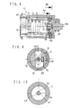
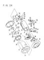
- Fig. 1 through 32 four embodiments of the cylinder lock according to the present invention will be described as follows.
- the cylinder lock 10 comprises a housing 11 provided with a first hole 12 and a sleeve 13 rotatably disposed within the first hole 12 of the housing 11.
- the sleeve 13 has a second hole 14 for rotatably receiving a key cylinder 16 and a slot 13a at the rear end for radially slidably receiving clutch means 20.
- Tumblers 17 are slidably disposed in slits 16a of the key cylinder 16 so that they are engaged with and disengaged from notches 15 of the sleeve 13.
- the notch 15 is communicated to the second hole 14 of the sleeve 13.
- Driver means 18 is rotatably disposed within the housing 11, and latch means 19 is disposed in a latch hole 21 formed in a cylindrical portion 16b of the key cylinder 16 so that the latch means 19 can be moved between an joint position (Figs. 1 and 3) for connecting the key cylinder 16 with the driver means 18 and a release position (Figs. 5 and 7) for disengaging the key cylinder 16 and the driver means 18.
- clutch means 20 which is slidably located within the slot 13a of the sleeve 13 may contact and carry the latch means 19 to the release position when the sleeve 13 is rotated in the housing 11 with an improper key.
- a cap 40 is attached to the front end of the housing 11 to cover a front surface of the key cylinder 16.
- An E-shaped ring 29 is attached to the rear end of the key cylinder 16 to prevent detachment of the lever 33 from the key cylinder 16 and detachment of the key cylinder 16 from the first hole 12 of the housing 11.
- the latch means 19 and a latch spring 27 are disposed within a latch hole 21 radially formed in the key cylinder 16 so that the latch means 19 is always resiliently urged outwardly in the radial direction by elastic force of the latch spring 27.
- the latch means 19 is generally formed into L-shape which comprises a spring holder 22 axially extending and a connector 23 radially extending.
- Formed in the key cylinder 16 is a latch hole 21 which has a deep cylindrical hole 21a for receiving the latch spring 27, and an enlarged hole 21 b for receiving the latch means 19.
- the spring holder 22 of the latch means 19 is disposed in the latch hole 21.
- the connector 23 of the latch means 19 is engaged with a recess 30 formed in the driver means 18, protruding from the latch hole 21 to drivingly connect the key cylinder 16 and the driver means 18. Accordingly, the key cylinder 16 is rotated together with the driver means 18 through the latch means 19 with a proper key.
- the clutch means 20 which is disposed in the slot 13a of the sleeve 13, includes a crescent body 20a, a pair of legs 24 radially extending from the crescent body 20a, a projection 20b radially extending from the crescent body 20a between these legs 24, a protrusion 25 axially extending from the crescent body 20a, and a convexity 26 radially protruding from the crescent body 20a.
- the clutch means 20 is resiliently pushed by a clutch spring 28 toward an inner wall of the first hole 12 of the housing 11 so that the convexity 26 is received within a groove 31 formed in the first hole 12.
- the protrusion 25 is not in contact with the connector 23 of the latch means 19 elastically pushed by the latch spring 27, and therefore the key cylinder 16 is smoothly rotated with the proper key.
- the convexity 26 of the clutch means 20 is retained engaged with the groove 31 of the first hole 12.
- the sleeve 13 is rotated with the key cylinder 16 and the clutch means 20 to rotate the convexity 26 away from the groove 31, thus causing the radially inward movement of the clutch means 20 against resilient force of the clutch spring 28.
- the protrusion 25 is moved radially inwardly to contact the connector 23 of the latch means 19 which is then radially inwardly moved against elastic force of the latch spring 27.
- the connector 23 of the latch means 19 moves into the enlarged hole 21 b of the latch hole 21 to release the driving connection between the connector 23 and the driver means 18.
- the lever 33 rotates together with the driver means 18.
- a lock device (not shown) is the lever 33 which is rotatably supported on the end of the key cylinder 16 with the E-shaped ring 29.
- a return spring 32 Disposed outside the housing 11 is a return spring 32 which has two ends 32a, 32b positioned to receive therebetween an outer protrusion 36 formed in the housing 11 and a bent stopper 34 formed in the lever 33 as shown in Fig. 7 for automatic returning the driver means 18 to the initial position after the driver means 18 is rotated.
- the groove 31 terminates with an opening 11 b in the front end of the housing 11 to drain water entering the housing 11 through the groove 31 and the opening 11 b.
- the tumblers 17 When a key is not inserted into the key cylinder 16, the tumblers 17 are engaged with the notch 15 of the sleeve 13 to connect the key cylinder 16 and the latch means 19 is in the joint position drivingly connecting the key cylinder 16 and the driver means 18 as shown in Fig. 3.
- the tumblers 17 When a proper key is inserted into a key hole 16b of the key cylinder 16, the tumblers 17 are moved into the retracted position within the key cylinder 16 to disengage the key cylinder 16 and the sleeve 13. With rotation of the key, the key cylinder 16 is rotated while the sleeve 13 is retained unturned in the condition wherein the convexity 26 of the clutch means 20 is urged in the groove 31 by the clutch spring 28.
- the driver means 18 and the lever 33 can be rotated to the locked or unlocked position with the rotation of the key cylinder 16 in driving connection with the key cylinder 16 through the driver means 18 and the latch means 19 as shown in Fig. 3.
- the return spring 32 When rotative force of the key is removed under the rotated condition of the key cylinder 16, the return spring 32 generates restorative force so that the lever 33, the driver means 18 and the key cylinder 16 are automatically returned to the initial position.
- the latch means 19 is pushed inwardly to the release position into the latch hole 21 by the protrusion 25 of the clutch means 20 to disengage the latch means 19 and the driver means 18.
- the projection 20b of the clutch means 20 is engaged with a groove 16c of the key cylinder 16 for integral rotation of the key cylinder 16 and clutch means 20.
- the driver means 18 is maintained in the unturned condition due to the disengagement with the key cylinder 16 by the latch means 19, thus preventing rotation of the lever 33 to the locked or unlocked position.
- the convexity 26 of the clutch means 20 is again engaged with the groove 31 of the housing 11 by integral rotation of the key cylinder 16 and sleeve 13 to return to the initial condition.
- Figs. 8 through 14 indicate a second embodiment of the present invention wherein each leg 24 of the clutch means 20 has a round notch 24a to receive the latch means 19.
- the latch means 19 includes a connecting portion 41 radially extending and received within a slit40 formed in the key cylinder 16; a column portion 42 connected with the connecting portion 41 and disposed in the round notches 24a of the legs 24; and a pair of lugs 43 axially protruding from the column portion 42.
- the driver means 18 has a shaft portion 45 having a rear end connected with a lock device (not shown); a flange portion 46 formed at the front end of the shaft 45; a pair of arcuate portions 47 projecting from the flange portion 46 to define a gap 48 between these arcuate portions 47.
- the clutch means 20 is disposed in the slot 13a of the sleeve 13 and elastically pushed by the clutch spring 28 toward the inner wall of the housing 11.
- the tumblers 17 release the engagement between the key cylinder 16 and the sleeve 13.
- the key cylinder 16 is rotated while the sleeve 13 is kept in the engaged position shown in Fig. 9 and remains unturned due to the engagement of the convexity 26 and the groove 31. Accordingly, the latch means 19 is maintained in the joint position in alignment with the center of the sleeve 13 as illustrated in Fig. 9.
- the latch means 19 With rotation of the key and the key cylinder 16, the latch means 19 is rotated so that as understood from Fig. 10, the lugs 43 of the latch means 19 contacts the arcuate portions 47 of the driver means 18 to transmit the rotation force to the driver means 18, thereby causing rotation of the driver means 18 to the locked or unlocked position.
- the driver means 18 and the key cylinder 16 are automatically returned by the return spring 32 similarly to the foregoing operation.
- the drive means 18 comprises an axial cylindrical hole 51 for receiving the cylindrical portion 16b of the key cylinder 16; a radial slit 52 and an axial groove 30 both communicating the cylindrical hole 51; and a pair of protrusions 35 axially extending.
- Locking means 55 is slidably disposed in the slit 52. As shown in Fig.
- the locking means 55 is formed generally into C-shape which comprises a protrusion 56 which can be engaged with a depression 11a formed in the housing 11; a pair of guide projections 55 slidably mounted in guide notches 52a which are formed in communication with the slit 52; and a hook portion 58 provided at a diametrically opposite side of the protrusion 56 so that the hook portion 58 may contact an axially extending lug 22a formed in the latch means 19.
- the guide projections 55 are outwardly urged by a locking spring 60 positioned in the drive means 18 so that the hook portion 58 is in contact with the lug 22a unless the lug 22a is moved into the latch hole 21 of the cylindrical portion 16b of the key cylinder 16.
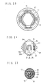
- the locking means 55 can be moved between the latched position of Fig. 26 wherein the protrusion 56 is engaged with the depression Ila of the housing 11 and the unlatched position of Fig. 23 wherein the protrusion 56 is disengaged from the depression Ila of the housing 11 in response to the movement of the latch means 19 between the joint position of Fig. 22 and the release position of Fig. 24. Accordingly, the locking spring 60 pushes the locking means 55 toward the latched position. As shown in Fig. 23, the locking means 55 is maintained in the unlatched position by the lug 22a of the latch means 19 in the joint position against the elastic force of the locking spring 60. When the latch means 19 is moved to the release position of Fig.
- the locking means 55 is moved to the latched position by elastic force of the locking spring 60 so that the protrusion 56 is engaged with the depression 11a.
- the latch spring 27 produces its elastic force stronger than that of the locking spring 60 while the latch means 19 is urged toward the recess 30 of the drive means 18 by the latch spring 27 positioned within the latch hole 21 of the key cylinder 16.
- the drive means 18 can be rotated by the latch means 19 of Fig. 22 which drivingly connects the key cylinder 16 and the drive means 18.
- the sleeve 13 is rotated with the key cylinder 16 so that the clutch means 20 is moved from the unturned position of Fig. 21 to the turned position of Fig. 25.
- the latch means 19 is inwardly moved from the joint position of Figs. 15 and 22 to the release position of Fig. 24, and hence a pair of protrusions 20b of the clutch means 20 are brought into engagement with a pair of notches 16d of the key cylinder 16.
- the latch means 19 is moved away from the recess 30 of the drive means 18 and the locking means 55 is moved from the unlatched position of Fig. 23 to the latched position of Fig. 26 so that the protrusion 56 is engaged with the depression 11a of the housing 11 to secure the drive means 18 to the housing 11, while the key cylinder 16 is disengaged from the drive means 18 in operation.
- the radial movement of the locking means 55 is effective to produce the lock in shorter size.
- Figs. 27 to 32 demonstrates a fourth embodiment of the present invention wherein locking means 61 is slidably mounted within the radial slit 52 of the drive means 18.
- An end 63 of the drive means 18 is rigidly positioned in an opening 33a of the lever 33.
- the locking means 61 is provided with a connecting hole 65 for receiving the lug 22a of the latch means 19, and a protrusion 64 engageable with the depression 11a of the housing 11.
- the locking means 61 When the locking means 61 is moved to the latched position wherein the protrusion 64 is in engagement with the depression 11a in use of a improper key, the lug 22a of the latch means 19 and the connecting hole 65 are retained in alignment with the central axis of the key cylinder 16 so that the lug 22a can be rotated in the connecting hole 65.
- Modes of the present invention are not limited to the embodiment described above, and may be modified in various ways.
- an electric switch may be provided to generate electric signals upon rotation of the driver means 18.
- Pin tumblers are also utilized in place of the disk tumblers 17.
- the latch spring 27 for the latch means 19 can resiliently urge the clutch means 20 without the clutch spring 28.
- the present invention provides a cylinder lock remarkably resistible against its destruction to effectively prevent such crimes as unauthorized intrusion and thieves.
- the cylinder lock according to the instant invention has excellent durability and operability without parts axially moved when a proper key is inserted and initially rotated because the key cylinder is usually in driving connection with the driver means. This means that no additional means is required to drivingly connect the key cylinder and the drive means during the initial rotation of the key cylinder. Accordingly, the invention's cylinder lock can be assembled with less number of sliding parts and with shorter whole length of the lock, reducing breakdown and prolonging its service life. Furthermore, the cylinder lock does not require the mechanically stronger structure at the front portion.
Landscapes
- Lock And Its Accessories (AREA)
- Actuator (AREA)
Applications Claiming Priority (4)
| Application Number | Priority Date | Filing Date | Title |
|---|---|---|---|
| JP33308893A JP3380611B2 (ja) | 1993-12-27 | 1993-12-27 | シリンダ錠 |
| JP333088/93 | 1993-12-27 | ||
| JP92735/94 | 1994-04-28 | ||
| JP09273594A JP3330728B2 (ja) | 1994-04-28 | 1994-04-28 | シリンダ錠 |
Publications (3)
| Publication Number | Publication Date |
|---|---|
| EP0659962A2 true EP0659962A2 (fr) | 1995-06-28 |
| EP0659962A3 EP0659962A3 (fr) | 1995-10-04 |
| EP0659962B1 EP0659962B1 (fr) | 1999-03-31 |
Family
ID=26434112
Family Applications (1)
| Application Number | Title | Priority Date | Filing Date |
|---|---|---|---|
| EP19940309886 Expired - Lifetime EP0659962B1 (fr) | 1993-12-27 | 1994-12-28 | Serrure de cylindre résistante à l'effraction |
Country Status (4)
| Country | Link |
|---|---|
| US (1) | US5640864A (fr) |
| EP (1) | EP0659962B1 (fr) |
| DE (1) | DE69417530T2 (fr) |
| ES (1) | ES2133501T3 (fr) |
Cited By (4)
| Publication number | Priority date | Publication date | Assignee | Title |
|---|---|---|---|---|
| GB2350146A (en) * | 1999-05-13 | 2000-11-22 | Rover Group | Motor vehicle lock assembly |
| WO2001042596A1 (fr) * | 1999-12-10 | 2001-06-14 | Huf Hülsbeck & Fürst Gmbh & Co. Kg | Dispositif de fermeture destine a des fonctions de fermeture pouvant etre executees notamment sur des vehicules |
| EP1399633A4 (fr) * | 2001-05-08 | 2005-03-23 | Southco | Verrou actionne par une clef a effet de verrouillage rotationnel et transitionnel combine |
| FR2882771A1 (fr) * | 2005-03-04 | 2006-09-08 | Valeo Securite Habitacle Sas | Verrou debrayable pour un mecanisme de serrure automobile |
Families Citing this family (44)
| Publication number | Priority date | Publication date | Assignee | Title |
|---|---|---|---|---|
| DE4412609A1 (de) * | 1994-04-13 | 1995-10-19 | Huelsbeck & Fuerst | Verschlußvorrichtung für insbesondere an Kraftfahrzeugen vollziehbare Schließfunktionen |
| JP3585192B2 (ja) * | 1995-11-14 | 2004-11-04 | 本田技研工業株式会社 | ハンドルロック装置 |
| JP3675936B2 (ja) * | 1996-03-22 | 2005-07-27 | 本田技研工業株式会社 | ハンドルロック装置 |
| FR2748513B1 (fr) * | 1996-05-10 | 1998-06-26 | Valeo Securite Habitacle | Verrou a debrayage axial pour un mecanisme de serrure de vehicule automobile |
| DE19639249C1 (de) * | 1996-09-25 | 1998-01-15 | Valeo Gmbh & Co Schliessyst Kg | Schließzylinder |
| ES2154538B1 (es) * | 1998-03-04 | 2001-09-01 | Talleres Escoriaza Sa | Cilindro de combinacion extraible desde el exterior para cerrojo |
| US6209369B1 (en) * | 1998-05-27 | 2001-04-03 | Royal Lock Corporation | Key actuated exterior cam lock |
| ES2171329T3 (es) * | 1998-05-30 | 2002-09-01 | Huf Huelsbeck & Fuerst Gmbh | Dispositivo de cierre para funciones de cierre a efectuar en especial en vehiculos. |
| US6058751A (en) * | 1998-09-08 | 2000-05-09 | Strattec Security Corporation | Free-wheeling lock |
| US6523382B1 (en) * | 1998-09-08 | 2003-02-25 | Strattec Security Corporation | Free wheeling lock assembly |
| SE517283C2 (sv) * | 1998-12-10 | 2002-05-21 | Volvo Personvagnar Ab | Anordning vid cylinderlås |
| FR2788478B1 (fr) * | 1999-01-15 | 2001-04-06 | Valeo Securite Habitacle | Antivol de direction de vehicule automobile |
| US20030118701A1 (en) * | 2000-03-14 | 2003-06-26 | Sprehe Gregory S. | Flangeless, reclosable fastener |
| US6446475B1 (en) * | 2000-06-12 | 2002-09-10 | Itt Manufacturing Enterprises, Inc. | Switchlock assembly with snap-in cam |
| US6527308B2 (en) * | 2000-11-01 | 2003-03-04 | S.P.E.P. Acquisitions Corp | Spring-loaded camlock |
| DE10162201A1 (de) * | 2000-12-20 | 2002-07-11 | Tokai Rika Co Ltd | Schlüsselzylinder und Verfahren zum Zusammenbau eines Schlüsselzylinders |
| US6634197B2 (en) * | 2002-01-22 | 2003-10-21 | Assa Ab | Lock device with removable core |
| TW510397U (en) * | 2002-03-11 | 2002-11-11 | Taiwan Fu Hsing Ind Co Ltd | Assembling structure of lock core for modified aid lock |
| US6711924B2 (en) * | 2002-06-18 | 2004-03-30 | Strattec Security Corporation | Freewheeling lock apparatus and method |
| US6978645B2 (en) * | 2003-06-23 | 2005-12-27 | Strattec Security Corporation | Freewheeling lock apparatus and method |
| JP4675238B2 (ja) * | 2003-09-12 | 2011-04-20 | 株式会社ユーシン | シリンダ錠 |
| US20050115288A1 (en) * | 2003-12-02 | 2005-06-02 | Burmahln Jedediah A. | Adjustable locking mechanism |
| US7406847B2 (en) * | 2004-07-02 | 2008-08-05 | Honda Lock Mfg. Co., Ltd. | Cylinder lock |
| USD520340S1 (en) | 2005-02-09 | 2006-05-09 | Royal Lock Corporation | External cam lock |
| FR2889859B1 (fr) * | 2005-08-17 | 2007-10-19 | Valeo Securite Habitacle Sas | Verrou debrayable pour un mecanisme de serrure automobile |
| JP4704935B2 (ja) * | 2006-03-07 | 2011-06-22 | 株式会社東海理化電機製作所 | シリンダ錠装置及び係合解除機構 |
| US7930916B2 (en) * | 2006-03-15 | 2011-04-26 | Kabushiki Kaisha Tokai-Rika-Denki-Seisakusho | Locking device and key |
| JP4740806B2 (ja) * | 2006-07-06 | 2011-08-03 | 株式会社東海理化電機製作所 | 錠装置 |
| JP4842874B2 (ja) * | 2007-03-30 | 2011-12-21 | 株式会社東海理化電機製作所 | 錠装置 |
| JP4926875B2 (ja) * | 2007-07-30 | 2012-05-09 | 株式会社東海理化電機製作所 | シリンダ錠、クラッチ装置、及びこれらシリンダ錠,クラッチ装置を備えた解錠装置 |
| JP5005459B2 (ja) * | 2007-07-30 | 2012-08-22 | 株式会社東海理化電機製作所 | シリンダ錠及びこれを備えた解錠装置 |
| JP4907489B2 (ja) * | 2007-10-25 | 2012-03-28 | 株式会社東海理化電機製作所 | シリンダ錠及びこれを備えた解錠装置 |
| US8276416B2 (en) * | 2009-02-18 | 2012-10-02 | Vsi, Llc | Master key lock, system and method |
| DE102010015684B4 (de) | 2010-04-21 | 2012-05-24 | Audi Ag | Schließzylinder, insbesondere für Türschlösser von Kraftfahrzeugen |
| DE202012100370U1 (de) * | 2012-02-03 | 2013-05-06 | Martin Lehmann Gmbh & Co. Kg | Wechselzylindersystem |
| WO2014094241A1 (fr) * | 2012-12-18 | 2014-06-26 | Lai Wenkun | Cylindre de serrure antivol à assemblage à mortaise |
| US20140331724A1 (en) * | 2013-05-07 | 2014-11-13 | Robert B. Ayrest | Camlock |
| JP6074812B2 (ja) * | 2013-12-13 | 2017-02-08 | 株式会社ホンダロック | シリンダ錠装置 |
| US9482036B2 (en) * | 2014-03-13 | 2016-11-01 | Ford Global Technologies, Llc | Self-draining keyed cylinder integrated into door trim |
| JP5964482B1 (ja) * | 2015-05-29 | 2016-08-03 | 株式会社東海理化電機製作所 | キーシリンダ装置 |
| TWM521102U (zh) * | 2015-08-28 | 2016-05-01 | Lintex Co Ltd | 鎖具 |
| CA2920469A1 (fr) | 2016-02-09 | 2017-08-09 | John Mcleod | Cheville de verrouillage resistant aux intemperies |
| BR112022021844A2 (pt) * | 2020-06-22 | 2023-01-24 | Essity Hygiene & Health Ab | Dispensador, estrutura de fechadura e conjunto de fechadura |
| CN113622753B (zh) * | 2021-08-03 | 2022-09-23 | 深圳市迈悍德实业有限公司 | 电子锁 |
Family Cites Families (6)
| Publication number | Priority date | Publication date | Assignee | Title |
|---|---|---|---|---|
| US3287944A (en) * | 1964-03-18 | 1966-11-29 | Gen Motors Corp | Locking means |
| FR2631067B1 (fr) * | 1988-05-04 | 1991-02-08 | Neiman Sa | Verrou a rotor debrayable |
| GB2228523B (en) * | 1989-02-23 | 1993-04-14 | Land Rover Uk Ltd | A locking mechanism |
| US5265453A (en) * | 1990-11-30 | 1993-11-30 | Alpha Corporation | Cylinder lock |
| US5285667A (en) * | 1990-11-30 | 1994-02-15 | Alpha Corporation | Cylinder lock |
| JP3017276B2 (ja) * | 1990-11-30 | 2000-03-06 | 株式会社アルファ | シリンダ錠 |
-
1994
- 1994-12-27 US US08/364,763 patent/US5640864A/en not_active Expired - Lifetime
- 1994-12-28 DE DE69417530T patent/DE69417530T2/de not_active Expired - Fee Related
- 1994-12-28 EP EP19940309886 patent/EP0659962B1/fr not_active Expired - Lifetime
- 1994-12-28 ES ES94309886T patent/ES2133501T3/es not_active Expired - Lifetime
Cited By (8)
| Publication number | Priority date | Publication date | Assignee | Title |
|---|---|---|---|---|
| GB2350146A (en) * | 1999-05-13 | 2000-11-22 | Rover Group | Motor vehicle lock assembly |
| EP1052351A3 (fr) * | 1999-05-13 | 2001-10-04 | Bayerische Motoren Werke Aktiengesellschaft | Ensemble de verrouillage pour véhicule automobile |
| WO2001042596A1 (fr) * | 1999-12-10 | 2001-06-14 | Huf Hülsbeck & Fürst Gmbh & Co. Kg | Dispositif de fermeture destine a des fonctions de fermeture pouvant etre executees notamment sur des vehicules |
| EP1399633A4 (fr) * | 2001-05-08 | 2005-03-23 | Southco | Verrou actionne par une clef a effet de verrouillage rotationnel et transitionnel combine |
| FR2882771A1 (fr) * | 2005-03-04 | 2006-09-08 | Valeo Securite Habitacle Sas | Verrou debrayable pour un mecanisme de serrure automobile |
| WO2006092373A1 (fr) * | 2005-03-04 | 2006-09-08 | Valeo Securite Habitacle (Sas) | Verrou debrayable pour un mecanisme de serrure automobile |
| US8011215B2 (en) | 2005-03-04 | 2011-09-06 | Valeo Securite Habitacle | Releasable lock for a motor vehicle locking system |
| CN101133221B (zh) * | 2005-03-04 | 2012-09-05 | 法雷奥安全座舱有限公司 | 用于机动车锁定系统的可释放锁具 |
Also Published As
| Publication number | Publication date |
|---|---|
| EP0659962B1 (fr) | 1999-03-31 |
| DE69417530T2 (de) | 1999-11-18 |
| EP0659962A3 (fr) | 1995-10-04 |
| DE69417530D1 (de) | 1999-05-06 |
| ES2133501T3 (es) | 1999-09-16 |
| US5640864A (en) | 1997-06-24 |
Similar Documents
| Publication | Publication Date | Title |
|---|---|---|
| EP0659962B1 (fr) | Serrure de cylindre résistante à l'effraction | |
| EP0675248B2 (fr) | Dispositif de serrure cylindrique résistant au déverrouillage non autorisé | |
| JP2742553B2 (ja) | ロック | |
| US5265453A (en) | Cylinder lock | |
| US4394821A (en) | Door lock mechanism | |
| US4048821A (en) | Combination padlock | |
| JPH0557391B2 (fr) | ||
| US6058751A (en) | Free-wheeling lock | |
| US5285667A (en) | Cylinder lock | |
| WO2005026476A1 (fr) | Verrou cylindrique | |
| US4333325A (en) | Steering shaft locking device | |
| US8347672B2 (en) | Lock cylinder particularly for functions which can be carried out in a vehicle | |
| US5511400A (en) | Lock mechanism for use in a securing device | |
| EP0679782B1 (fr) | Cylindre à clé à retour automatique pour serrure cylindrique | |
| JP3330728B2 (ja) | シリンダ錠 | |
| JP3380611B2 (ja) | シリンダ錠 | |
| US7339472B2 (en) | Self-adjusting cam assembly | |
| JP4411567B2 (ja) | シリンダ錠 | |
| GB2068346A (en) | Caps for vehicle filler pipes | |
| CN218406981U (zh) | 挂锁 | |
| JP3050628B2 (ja) | シリンダ錠 | |
| JPH0332215Y2 (fr) | ||
| KR100383076B1 (ko) | 프리 휠링식 잠금 장치 | |
| JP4403395B2 (ja) | シリンダ錠 | |
| JPH0533534A (ja) | シリンダ錠 |
Legal Events
| Date | Code | Title | Description |
|---|---|---|---|
| PUAI | Public reference made under article 153(3) epc to a published international application that has entered the european phase |
Free format text: ORIGINAL CODE: 0009012 |
|
| AK | Designated contracting states |
Kind code of ref document: A2 Designated state(s): DE ES FR GB |
|
| PUAL | Search report despatched |
Free format text: ORIGINAL CODE: 0009013 |
|
| RHK1 | Main classification (correction) |
Ipc: E05B 17/00 |
|
| AK | Designated contracting states |
Kind code of ref document: A3 Designated state(s): DE ES FR GB |
|
| 17P | Request for examination filed |
Effective date: 19960208 |
|
| 17Q | First examination report despatched |
Effective date: 19970527 |
|
| GRAG | Despatch of communication of intention to grant |
Free format text: ORIGINAL CODE: EPIDOS AGRA |
|
| GRAG | Despatch of communication of intention to grant |
Free format text: ORIGINAL CODE: EPIDOS AGRA |
|
| GRAH | Despatch of communication of intention to grant a patent |
Free format text: ORIGINAL CODE: EPIDOS IGRA |
|
| GRAH | Despatch of communication of intention to grant a patent |
Free format text: ORIGINAL CODE: EPIDOS IGRA |
|
| GRAA | (expected) grant |
Free format text: ORIGINAL CODE: 0009210 |
|
| AK | Designated contracting states |
Kind code of ref document: B1 Designated state(s): DE ES FR GB |
|
| REF | Corresponds to: |
Ref document number: 69417530 Country of ref document: DE Date of ref document: 19990506 |
|
| ET | Fr: translation filed | ||
| REG | Reference to a national code |
Ref country code: ES Ref legal event code: FG2A Ref document number: 2133501 Country of ref document: ES Kind code of ref document: T3 |
|
| PLBE | No opposition filed within time limit |
Free format text: ORIGINAL CODE: 0009261 |
|
| STAA | Information on the status of an ep patent application or granted ep patent |
Free format text: STATUS: NO OPPOSITION FILED WITHIN TIME LIMIT |
|
| 26N | No opposition filed | ||
| REG | Reference to a national code |
Ref country code: GB Ref legal event code: IF02 |
|
| PGFP | Annual fee paid to national office [announced via postgrant information from national office to epo] |
Ref country code: FR Payment date: 20061208 Year of fee payment: 13 |
|
| PGFP | Annual fee paid to national office [announced via postgrant information from national office to epo] |
Ref country code: DE Payment date: 20061221 Year of fee payment: 13 |
|
| PGFP | Annual fee paid to national office [announced via postgrant information from national office to epo] |
Ref country code: GB Payment date: 20061227 Year of fee payment: 13 |
|
| PGFP | Annual fee paid to national office [announced via postgrant information from national office to epo] |
Ref country code: ES Payment date: 20070122 Year of fee payment: 13 |
|
| GBPC | Gb: european patent ceased through non-payment of renewal fee |
Effective date: 20071228 |
|
| PG25 | Lapsed in a contracting state [announced via postgrant information from national office to epo] |
Ref country code: DE Free format text: LAPSE BECAUSE OF NON-PAYMENT OF DUE FEES Effective date: 20080701 |
|
| REG | Reference to a national code |
Ref country code: FR Ref legal event code: ST Effective date: 20081020 |
|
| PG25 | Lapsed in a contracting state [announced via postgrant information from national office to epo] |
Ref country code: GB Free format text: LAPSE BECAUSE OF NON-PAYMENT OF DUE FEES Effective date: 20071228 |
|
| REG | Reference to a national code |
Ref country code: ES Ref legal event code: FD2A Effective date: 20071229 |
|
| PG25 | Lapsed in a contracting state [announced via postgrant information from national office to epo] |
Ref country code: FR Free format text: LAPSE BECAUSE OF NON-PAYMENT OF DUE FEES Effective date: 20071231 Ref country code: ES Free format text: LAPSE BECAUSE OF NON-PAYMENT OF DUE FEES Effective date: 20071229 |