EP0660148B1 - Procédé de fabrication d'un ruban à fibres optiques - Google Patents
Procédé de fabrication d'un ruban à fibres optiques Download PDFInfo
- Publication number
- EP0660148B1 EP0660148B1 EP19940308579 EP94308579A EP0660148B1 EP 0660148 B1 EP0660148 B1 EP 0660148B1 EP 19940308579 EP19940308579 EP 19940308579 EP 94308579 A EP94308579 A EP 94308579A EP 0660148 B1 EP0660148 B1 EP 0660148B1
- Authority
- EP
- European Patent Office
- Prior art keywords
- radiation
- curing
- array
- set forth
- ribbon
- Prior art date
- Legal status (The legal status is an assumption and is not a legal conclusion. Google has not performed a legal analysis and makes no representation as to the accuracy of the status listed.)
- Expired - Lifetime
Links
Images

Classifications
-
- G—PHYSICS
- G02—OPTICS
- G02B—OPTICAL ELEMENTS, SYSTEMS OR APPARATUS
- G02B6/00—Light guides; Structural details of arrangements comprising light guides and other optical elements, e.g. couplings
- G02B6/44—Mechanical structures for providing tensile strength and external protection for fibres, e.g. optical transmission cables
- G02B6/4479—Manufacturing methods of optical cables
- G02B6/448—Ribbon cables
Definitions
- the present invention relates to an improved apparatus and process for manufacturing optical fiber ribbons.
- optical fibers Because of their high bandwidth capacity and small physical size, optical fibers are now used in a wide variety of applications. However, optical fibers are fragile, and are also susceptible to stress and bending, which cause optical attenuation. Consequently, adequate mechanical protection of the fibers is necessary.
- One way to protect optical fibers is to arrange and package them into a planar array of individual fibers covered by a curable coating material, forming a ribbon-like structure.
- This ribbon structure not only provides for the mechanical protection of the individual optical fibers, but through orderly alignment provides stability, and also makes splicing easier. See, for example, U.S. Patent No. 4,900,125.
- optical fiber ribbons are of two types: thin or thick.
- Thick ribbons i.e. having a coating thickness of about 10 microns
- planar arrays of optical fibers covered by a thick coating of curable material suffer warpage problems, are thicker than necessary if the sole purpose of the coating is to provide protection for the fiber, decrease the packing efficiency, i.e. the number of fibers which can be accommodated in a given volume, and create undesirable stresses due to thermal expansion. Therefore, it is desirable to keep the coating thickness to a minimum.
- Thin ribbons have a much thinner coating of curable material, e.g. about 25 microns or less, covering the optical fiber array than the thick variety, requiring less coating material and therefore having greater packing efficiency.
- the films are too thin, they will tend to form depressions or menisci between the fiber interstices during curing, resulting in a nonplanar ribbon surface.
- variations in fiber size or alignment within the array also cause the outer surface of the ribbon to become nonplanar, forming edges or "ribs" which may interlock with other ribbons.
- a further difficulty in using thin film ribbons is the need for a high interfiber bonding strength.
- Thin films unlike the thick variety may not provide sufficient support for the ribbon structure, thereby requiring stronger interfiber adhesive materials.
- increased interfiber bonding strength affects the mobility of the individual fibers and their optical performance within cables.
- the bonding material must be removed, and the strong adhesives may remove identifying ink markings or colors on the individual fibers as well, rendering the individual fibers unidentifiable and seriously complicating the splicing operation.
- WO-A-92/18892 discloses a method wherein synthetic material is applied to an optical fiber ribbon and cured.
- focussing lenses direct UV radiation to opposite faces of the ribbon. Radiation is transmitted to the lenses through light conductors using a parabolic (non-focussing) reflector (see Figure 3).
- An object of the invention is to overcome at least some of the above mentioned disadvantages.
- the invention provides a process of manufacturing an optical fiber ribbon containing a plurality of longitudinally extending optical fibers and having differently facing major surfaces without curvature transversely to the ribbon length, comprising the following steps:
- the invention also includes an apparatus for manufacturing an optical fiber ribbon having a plurality of longitudinally extending optical fibers therein, comprising:
- the invention also includes a process of manufacturing an optical fiber ribbon including providing an elongate assembly comprising a radiation curable coating On a planar array of optical fibers, and curing said coating by directing curing radiation onto each of two directly opposite axially extending outer major surface portions of said coated array, wherein said curing is effected using directly oppositely disposed radiation means each comprising a radiation focussing reflector and a curing radiation emitter disposed between its respective reflector and said assembly, said radiation means being arranged such that substantially the same amount of radiation is directly and simultaneously focussed onto each of said outer surface portions of said array.
- the invention also includes apparatus for curing a radiation curable coating of an elongate assembly comprising said coating on a planar array of optical fibers, said apparatus comprising directly oppositely disposed first and second radiation means, each of which comprises a radiation focussing reflector and a radiation emitter, and means for positioning the coated array between said radiation means such that, in use, said radiation means simultaneously focus substantially the same amount of radiation onto each of two directly opposite axially extending outer surface portions of said radiation curable coating.
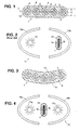
- FIG. 1 there is shown a cross-sectional view of an optical fiber ribbon produced in accordance with the process described herein with reference to Figs 4 to 9, which is designated generally by the numeral 1.
- the ribbon comprises a plurality of longitudinally extending individual optical fibers 2, each comprising a core 3 and a cladding 4, and each preferably having a layer 5 of a conventional protective coating material, e.g. a plastic, thereon.
- a conventional protective coating material e.g. a plastic
- the plurality of longitudinally extending fibers 2, each preferably having the same or similar diameters d, are arranged in a planar array 6, the center of each fiber being aligned along an axis 7 transverse to the longitudinal direction of the optical fibers, and the entire array being covered with a cured layer 8 of adhesive matrix coating material, e.g. UV curable acrylate, not only filling the interstices 9 between adjacent optical fibers 2 but also covering the fibers 2, including the portions 10 of the end fibers in the array 6.
- adhesive matrix coating material e.g. UV curable acrylate
- a conventional elliptical curing oven is illustrated schematically in Fig. 2 where the numeral 11 designates generally an elliptical curing oven having a single elongated lamp 12 located at one focal axis of an elliptical reflector 13a surface. Lamp 12 preferably radiates energy at a wavelength which will cause the coating material layer 8 to cure, e.g.
- UV ultraviolet
- the elliptical reflector 13a focuses most of the radiant energy from the lamp 12 on the ribbon 1 within a quartz tube 14 located at the focal point of a second elliptical reflector 13b, and also directs radiant energy onto the surface of reflector 13b.
- the radiant energy is emitted along the axial length of the lamp 12 and reflected onto the ribbon 1 by both of the elliptical reflectors 13a and 13b, preferably distributing the radiant energy uniformly along the axial length of the tube 14.
- the ribbon 1 with the uncured plastic material layer 8 thereon is passed longitudinally within the bore of the quartz tube 14 where it is subjected to the radiant energy reflected by the reflectors 13a and 13b and received directly from the lamp 12 causing the material of the layer 8 to commence to cure.
- the optical efficiency (energy received and reflected by the reflectors vs. total energy emitted by the radiation source) of the conventional oven configuration shown in Fig. 2 is approximately 75%, i.e. only 75% of the emitted radiation actually contacts the uncured coating material layer 8 on ribbon 1 within quartz tube 14.
- the radiation striking the faces of flat ribbon 1 is not uniform. Instead, the amount of radiation energy received by the face 1a nearer the lamp 12, directly and indirectly from lamp 12, is approximately 70% of the radiation striking the entire ribbon 1. The remaining 30% strikes the opposite ribbon face 1b indirectly, i.e. reflected off of reflector 13b. Therefore the faces 1a and 1b of ribbon 1 receive different amounts of curing radiation, both faces cure at different rates and thus contract at different rates.
- This 70/30 curing differential causes greater contraction along the ribbon face having higher UV exposure, face 1a, resulting in warpage of the ribbon 1, as shown in Fig. 3.
- One attempt to provide uniform irradiation of ribbon 1 is to use a pair of conventional ovens of the type shown in Fig. 2 in series with each other, i.e. displaced with respect to each other in the direction of advance of the ribbon, but with the oven components interchanged. Face 1a, while passing through a first oven, receives 70% of the curing radiation and face 1b 30%, but upon entry to a second and reversed oven, the face 1b is nearer the lamp 12 and these percentages are reversed. However, prior to reaching the second oven, uneven curing and the subsequent uneven contraction has already begun, which results in a warped ribbon.
- Warpage damage due to curing variations is especially problematic in the case of Original Equipment Manufacturers ("OEM”) reflectors which, not being designed specifically for optical fiber ribbon production, may vary greatly in reflective and focal properties, resulting in commensurate variance in radiation dosages striking the faces of ribbon 1.
- OEM Original Equipment Manufacturers
- Both reflectors 16a and 16b direct the radiation toward each other and uniformly and simultaneously focus the radiant energy from lamps 17a and 17b, respectively, onto directly opposite axially extending outer surface portions of the ribbon 1 in a quartz tube 18, which may be the sane as the quartz tube 14, through which the ribbon 1, having layer 8 of a curable coating material thereon is passed.
- a quartz tube which may be the sane as the quartz tube 14, through which the ribbon 1, having layer 8 of a curable coating material thereon is passed.
- the quartz tube is shown with a corresponding shape to that of the ribbon, it may be circular.
- the oven configuration described herein with reference to Figs 4 to 9 provides a one-pass simultaneous and uniform curing treatment at both faces, 1a and 1b, of the fiber ribbon 1 positioned between the radiation means 16a, 17a and 16b, 17b, avoiding the uneven contraction and warpage damage to fiber optics ribbons caused by conventional oven systems.
- a problem with the use of such reflectors is that not only the desired energy wavelengths, e.g. short wavelengths of UV radiation, are reflected and directed by the reflectors 16a and 16b upon the ribbon 1.
- conventional reflectors reflect the entire spectrum of radiant energy emitted by the lamps, which includes not only the desired UV radiation but undesired longer wavelength visible light and Infrared ("IR") radiation as well. Since the principal effect of IR radiation is heat, reflected IR heat energy focused upon the faces of ribbon 1 can heat the surfaces of faces 1a and 1b instantaneously to high temperatures which do not reduce quickly, thereby often causing warpage and/or thermal damage to the structure of the ribbon 1.
- the heat problem of IR radiation may be reduced by employing dichroic reflectors, which by their nature are double refracting, i.e. have good reflectance for one wavelength, e.g. UV, but poor reflectance for another, e.g. IR, thereby providing focused UV curing radiation while reducing the unwanted IR radiation.
- Dichroic reflectors are formed by coating on the reflector surface a thin layer of material having an index of refraction selected to either transmit, reflect or absorb the incident radiation, and are available, for example, from the aforesaid Fusion Systems Corporation.
- Reflector 19 has a reflective surface 19a preferably made of an opaque material, e.g. stainless steel, and capable of forming a specular finish upon polishing.
- a thin layer 20 of an absorbing coating, preferably black, is deposited on the polished reflective surface 19a and also polished to a specular finish.
- One or more layers 21 of a dielectric material having dichroic properties are then deposited atop the coating 20 on said dichroic reflector 19, and similarly polished to a specular finish.
- several coatings or "stacks" of dielectric coating layers 21 are deposited and polished separately before deposition of a subsequent layer. Their reflective effects are cumulative.
- radiant energy 22 in the short wavelength ultraviolet spectrum is reflected and focused by the dielectric material coating layer 21 whereas the longer wavelengths, visible light 23 and infrared radiation 24, are absorbed by the absorptive coating layer 20.
- Thermal energy absorbed by layer 20 is conducted to the dichroic reflector 19, which is preferably made of a material that is thermally conductive, and transferred to the exterior surface side 19b of the reflector 19. This conducted heat is easily removed by convective cooling, e.g., an air flow on the exterior surface 19b.
- a transparent reflector 25 and dichroic dielectric coating layer 21 reflects the shorter UV 22 wavelengths, as in the oven described with reference to Fig. 6, but allows the longer wavelengths of visible light 23 and IR radiation 24 to pass through instead of being absorbed.
- An advantage of this oven over the previous one is that no cooling device would be necessary.
- high quality thin and thick optical fiber ribbons can be manufactured by a process using the oven configuration described herein with reference to Figs 4 to 9.
- Uniform rates of curing and contraction of the curable coating material layer 8 and reduced radiant heating of the ribbon, along both faces of ribbon 1 allows the manufacture of much thinner ribbons than possible in conventional curing ovens.
- Uniformity in radiation has the added advantage of benefiting fully from the many recent advances in fiber planarity and extrusion techniques, optimizing and minimizing the film thicknesses required for both the thin and thick ribbon types.
- FIG. 8 A process is illustrated schematically in Fig. 8. Although the schematic is horizontally related, the apparatus may be a vertical assembly.
- Individual optical fibers 2 are formed by conventional techniques, and preferably, each is coated with protective coating material 5 to protect each fiber 2.
- a plurality, i.e two or more, of the fibers 2, preferably having identical diameters, are aligned longitudinally into parallel, planar array 6 of closely adjacent fibers, seen along an edge in Fig. 8, by aligning means as they are advanced along their lengths.
- the fibers can be coated or marked with UV or thermally curable, colored inks for identification purposes.
- the array 6 of longitudinally aligned and parallel fibers 2 then passes through an extrusion die 27, which evenly extrudes a curable coating material 8, such as an UV curable acrylate resin, onto array 6 as the fibers are advanced, filling the interstices 9 between the individual fibers 2, and coating the peripheral portions 10 of the end fibers, resulting in a smooth and planar ribbon.
- a curable coating material 8 such as an UV curable acrylate resin
- the extruded coating material layer 8 is then irradiated in oven 15 by radiation of a wavelength which will cause the coating to cure, e.g. ultraviolet radiation.
- other wavelengths e.g.
- IR are not directed on the surface of the ribbon by using dichroic reflectors 16a and 16b of the type described in connection with Figs. 6 and 7.
- the thickness of the material extruded by die 27 onto planar fiber array 6 varies according to the particular ribbon type desired, i.e. thin or thick.
- Coating material for the layer 8 preferably has a tensile modulus of at least 30 MPa and relatively low adhesion to the fibers 2, which not only binds the individual optical fibers 2 together, but also restricts the fibers 2 from moving relative to each other during handling while permitting the layer 8 to be relatively easily stripped from the fibers for connection purposes without removing any identification marking on the fibers 2.
- Such materials are known in the art.
- the material for the layer 8 can have a bonding to the coating material of the layer 5 which permits interfiber movement, examples of such materials being set forth in U.S. Patent No. 4,900,126. Normally, unless the layer 5 has been coated with a release agent prior to the application of the coating material for the layer 8, the material of the layer 8 will be different from the material of the layer 5.
- Thicker layers of extruded coating material 8 are required on ribbons manufactured in conventional equipment which has higher incident IR radiation, lessor quality extrusion dies and/or non-uniform radiation dosages in order to guarantee a minimum spot thickness due to misalignment of the fibers. Because of the manufacturing improvements of the process described herein with reference to Figs 4 to 9, however, much thinner extrusion coatings for both thin and thick ribbons are now possible. Whereas conventional "thin" ribbons have, as a practical matter, a thickness for the layer 8 of approximately 25 microns, thin ribbons manufactured according to the process described herein with reference to Figs 4 to 9 have a layer 8 thickness of approximately 5 - 15 microns.
- the thickness can now be reduced to 30 - 60 microns.
- the thickness of the layer 8 is measured along a radius of an optical fiber 2 which is normal to the plane defined by the longitudinal axes of the optical fibers 2.
- the coated array 6 After extruding the layer 8 of curable coating material onto fiber array 6, the coated array 6 passes through the oven 15, which simultaneously exposes both major surfaces or faces 1a and 1b to substantially equal curing radiation and uniformly cures the layer 8.
- the duration of exposure and the amount of radiation to which the ribbon is exposed is controlled by the speed of the ribbon 1 through the improved oven and by the radiation level of the lamps 17a and 17b.
- the simultaneous and uniform irradiation of the coating material of the layer 8 causes uniform curing of the layer 8 as the ribbon is advanced and eliminates warping.
- the cured or still curing ribbon 1 then passes onto a second pulley 28 and then to a rotating drum (not shown), onto which the ribbon can be wound.
- the identifying markings or coatings on the fibers 2 can be cured by the radiation from the lamps 17a and 17b, e.g. UV radiation, such markings or coatings will cure, or commence to cure, at the same time as the layer 8.
- the encapsulating layer can comprise a plurality of coatings of the same or different materials.
- the cured ribbon 1 formed in the above process can be passed through a bath of a molten plastic coating material to form a layer 29 (Fig. 9) or passed through a second extrusion die similar to die 27 for depositing a layer 29 of the plastic coating material on the ribbon 1.
- the plastic coating material for the layer 29 is an acrylate resin or other radiation curable plastic which also cures when subjected to UV radiation, forming a hard protective outer coating, as shown in Fig. 9.
- this improved process allows for much thinner films or layers 29 of plastic coating material than the prior art.
- the total thickness of the layers 8 and 29 of protective plastic coatings on optical fiber ribbons can be reduced from 25 microns as in the prior art, down to 5 - 15 microns with the use of the methods and apparatus described herein with reference to Figs 4 to 9.
- Plastic coating material 29 forms a protective layer around ribbon 1 and preferably has a high modulus, i.e. a tensile modulus of at least 30 MPa and bonding of layer 29 to the fibers 2 need not be considered and it can be of a material different from the material for the layer 8, thereby providing a robust package for the optical fibers 2 encased therein.
- a further advantage of simultaneous and uniform irradiation of ribbon 1 is that unlike conventional ribbon manufacturing the process is not prone to producing warped or curved ribbons at any particular production speed.
- a process for manufacturing an optical fiber ribbon array containing two or more fibers is disclosed.
- the first step in the process is to gather and align the individual fibers longitudinally and parallel to one another and coplanar, forming a planar optical fiber array.
- a curable coating material is then extruded on the optical fiber array and is thereafter cured by radiation of a wavelength which will cause the coating to cure, e.g. ultraviolet.
- the uniform curing of the coating material may be done by the oven with the pair of opposed elliptical reflectors 16a, 16b sharing a common focal axis, each reflector 16a, 16b having a curing lamp 17a, 17b positioned within its second focal axis, the one not commonly shared.
- the pair of opposed reflectors 16a, 16b may have a layer 21 of a dichroic substance that selectively reflects radiation of a desired wavelength for curing purposes, and prevents the transmission of radiation of different and undesirable wavelengths.
Landscapes
- Physics & Mathematics (AREA)
- Engineering & Computer Science (AREA)
- Manufacturing & Machinery (AREA)
- General Physics & Mathematics (AREA)
- Optics & Photonics (AREA)
- Surface Treatment Of Glass Fibres Or Filaments (AREA)
- Optical Fibers, Optical Fiber Cores, And Optical Fiber Bundles (AREA)
- Optical Couplings Of Light Guides (AREA)
Claims (24)
- Procédé de fabrication d'un ruban de fibres optiques (1) contenant une pluralité de fibres optiques (2) s'étendant de manière longitudinale et comportant des faces principales (1a, 1b) orientées différemment sans courbure transversalement à la longueur du ruban, comprenant les étapes suivantes :(a) aligner lesdites fibres optiques (2) s'étendant de manière longitudinale dans un réseau sensiblement plan de fibres optiques (2) adjacentes et parallèles, les axes longitudinaux des fibres (2) étant dans un plan rectiligne;(b) extruder sur ledit réseau plan de fibres optiques une couche (8) de matériau de revêtement durcissable sous l'action d'un rayonnement afin de constituer un réseau plan enrobé (6) de fibres optiques parallèles avec une première et une seconde faces principales (1a, 1b) enrobées orientées différemment, ledit réseau (6) présentant une épaisseur entre lesdites faces principales moindre que la largeur du réseau dans la direction transversale à ladite épaisseur; et(c) faire passer le réseau plan enrobé (6) entre deux sources de rayonnement de durcissement espacées et disposées de façon directement opposée l'une par rapport à l'autre en des côtés opposés du réseau (6) passant entre elles, chacune desdites sources incluant un émetteur de rayonnement de durcissement respectif (17a, 17b) et un réflecteur de concentration des rayons respectif (16a, 16b), chaque émetteur se trouvant entre le réflecteur qui lui est associé et le réseau plan enrobé, les deux dites sources (16a, 17a et 16b, 17b) étant disposées pour diriger le rayonnement de durcissement l'une vers l'autre et pour concentrer uniformément et simultanément le rayonnement de durcissement sur des parties de faces respectives directement opposées s'étendant de manière axiale de ladite première face (1a) et de ladite seconde face (1b) situées entre elles de façon que le rayonnement de durcissement se heurte uniformément et simultanément auxdites parties de faces.
- Procédé selon la revendication 1, dans lequel ledit matériau de revêtement durcissable sous l'action d'un rayonnement est de la résine d'acrylate.
- Procédé selon la revendication 1 ou 2, dans lequel ladite couche de matériau de revêtement durcissable (8), une fois durcie, présente un module en traction d'au moins 30 MPa.
- Procédé selon l'une quelconque des revendications 1, 2 ou 3, dans lequel ladite couche de matériau de revêtement durcissable (8), une fois durcie, présente une épaisseur d'environ 5 à 15 micromètres.
- Procédé selon l'une quelconque des revendications 1, 2 ou 3, dans lequel ladite couche de matériau de revêtement durcissable (8), une fois durcie, présente une épaisseur d'environ 30 à 60 micromètres.
- Procédé selon l'une quelconque des revendications 1 à 5, dans lequel l'une au moins desdites fibres optiques est marquée avec une encre durcissable à des fins d'identification.
- Procédé selon la revendication 6, dans lequel ladite encre est durcie par un rayonnement ultraviolet.
- Procédé selon la revendication 6, dans lequel ladite encre est durcie de manière thermique.
- Procédé selon l'une quelconque des revendications 1 à 8, dans lequel un agent de séparation est intercalé entre chacune desdites fibres optiques (2) et ladite couche de matériau de revêtement durcissable (8).
- Procédé selon l'une quelconque des revendications 1 à 9, dans lequel les étapes (b) et (c) sont répétées, superposant des couches successives (8, 29) de matériau durci sur ledit réseau (6).
- Procédé selon l'une quelconque des revendications 1 à 9, comprenant de plus les étapes consistant à :extruder sur le ruban de fibres optiques (1) une couche supplémentaire (29) de matériau de revêtement plastique durcissable sous l'action d'un rayonnement pour constituer un ruban de fibres optiques enrobé avec une première et une seconde faces disposées de manière opposée; etfaire passer ledit ruban durci (1) sur lequel se trouve ladite couche supplémentaire (29) de revêtement plastique durcissable sous l'action d'un rayonnement entre deux sources de rayonnement de durcissement espacées, ces deux sources dirigeant simultanément le rayonnement de durcissement l'une vers l'autre et respectivement, sur les première et seconde faces susmentionnées.
- Procédé selon l'une quelconque des revendications précédentes, dans lequel lesdits réflecteurs (16a, 16b) sont elliptiques.
- Procédé selon l'une quelconque des revendications précédentes, dans lequel lesdits réflecteurs (16a, 16b) sont disposés de façon à partager un axe focal commun.
- Procédé selon l'une quelconque des revendications précédentes, dans lequel lesdits réflecteurs (16a, 16b) sont dichroïques.
- Procédé selon l'une quelconque des revendications 1 à 14, dans lequel ledit rayonnement de durcissement est un rayonnement ultraviolet.
- Dispositif permettant de fabriquer un ruban de fibres optiques (1) contenant une pluralité de fibres optiques (2) s'étendant de manière longitudinale, comprenant :un moyen servant à aligner lesdites fibres optiques s'étendant de manière longitudinale en un réseau sensiblement plan (6) de fibres optiques parallèles et adjacentes tandis qu'elles avancent dans la direction de leur longueur;un moyen (27) servant à extruder une couche (8) de matériau de revêtement durcissable sous l'action d'un rayonnement sur ledit réseau plan (6) de fibres optiques tandis que lesdites fibres optiques avancent pour constituer un ruban (1) comportant une largeur transversale à la direction du mouvement plus grande que l'épaisseur du ruban transversale à la largeur du ruban, et à constituer une première et une seconde faces principales (1a, 1b) orientées différemment sur ladite couche (8);des moyens formant four, servant à durcir ladite couche (8) de matériau de revêtement durcissable sous l'action d'un rayonnement sur ledit réseau plan (6) par un rayonnement de durcissement tandis que ledit réseau avance, lesdits moyens formant four comprenant :une première lampe (17a) adjacente à ladite première face (1a) de ladite couche (8) destinée à émettre un rayonnement permettant de durcir ladite couche (8), et une seconde lampe (17b) adjacente à ladite seconde face (1b) de ladite couche (8) mais de l'autre côté dudit réseau (6) par rapport à ladite première lampe (17a) destinée à émettre un rayonnement de durcissement; etun premier réflecteur (16a) dirigeant ledit rayonnement de durcissement provenant de ladite première lampe (17a) vers ladite seconde lampe (17b) et concentrant ledit rayonnement de durcissement sur ladite première face (1a) dudit réseau plan (6) et un second réflecteur (16b) dirigeant ledit rayonnement de durcissement provenant de ladite seconde lampe (17b) vers ladite première lampe (17a) et concentrant ledit rayonnement de durcissement sur ladite seconde face (1b) dudit réseau plan (6);lesdits moyens formant four durcissant de cette manière, uniformément et simultanément, ladite couche (8) de matériau de revêtement durcissable sous l'action d'un rayonnement sur ledit réseau plan (6).
- Dispositif selon la revendication 16, dans lequel lesdits premier et second réflecteurs (16a, 16b) sont elliptiques.
- Dispositif selon la revendication 17, dans lequel lesdits premier et second réflecteurs elliptiques (16a, 16b) partagent un axe focal commun le long dudit réseau plan (6).
- Dispositif selon l'une quelconque des revendications 16, 17 ou 18 dans lequel lesdits premier et second réflecteurs (16a, 16b) sont dichroïques.
- Dispositif selon l'une quelconque des revendications 16 à 19, dans lequel lesdites première et seconde lampes (17a, 17b) sont des émetteurs de rayonnement ultraviolet.
- Dispositif selon l'une quelconque des revendications 16 à 20, dans lequel lesdits moyens formant four comprennent en plus :un moyen formant tube (18) qui est transparent au moins partiellement audit rayonnement de durcissement et servant à encercler ledit réseau plan (6) de fibres optiques couvert par ladite couche (8) de matériau de revêtement durcissable sous l'action d'un rayonnement et permettant le passage dudit réseau dans lesdits moyens formant four, ledit moyen formant tube (18) étant disposé entre ladite première lampe (17a) et ladite seconde lampe (17b).
- Dispositif selon la revendication 21, dans lequel ledit moyen formant tube (18) est un tube de quartz dont l'alésage est plus grand que la dimension maximum dudit réseau plan (6) de fibres optiques couvert de ladite couche (8).
- Procédé de fabrication d'un ruban de fibres optiques (1) incluant les étapes consistant à prévoir un ensemble allongé comprenant un revêtement (8) durcissable sous l'action d'un rayonnement sur un réseau plan (6) de fibres optiques (2) et à durcir ledit revêtement (8) en dirigeant un rayonnement de durcissement sur deux parties de faces principales externes dudit réseau enrobé directement opposées s'étendant de manière axiale, dans lequel ledit durcissement est effectué en utilisant des moyens de rayonnement disposés de manière directement opposée, chacun d'eux comprenant un réflecteur (16a, 16b) de concentration de rayonnement et un émetteur (17a, 17b) de rayonnement de durcissement disposé entre son réflecteur (16a, 16b) respectif et ledit ensemble (6, 8), lesdits moyens de rayonnement étant disposés de façon qu'une quantité sensiblement identique de rayonnement soit concentrée directement et simultanément sur chacune desdites parties de faces principales externes dudit réseau.
- Dispositif servant à durcir un revêtement (8) durcissable sous l'action d'un rayonnement d'un ensemble allongé comprenant ledit revêtement (8) disposé sur un réseau plan (6) de fibres optiques (2), ledit dispositif comprenant un premier et un second moyens de rayonnement placés de manière directement opposée, chacun d'eux comprenant un réflecteur (16a, 16b) de concentration de rayonnement et un émetteur (17a, 17b) de rayonnement, et un moyen servant à positionner le réseau enrobé entre lesdits moyens de rayonnement (16a, 16b, 17a, 17b) de façon que, au cours de l'utilisation, lesdits moyens de rayonnement concentrent simultanément une quantité sensiblement identique de rayonnement sur deux parties de faces externes directement opposées s'étendant de manière axiale dudit revêtement (8) durcissable sous l'action d'un rayonnement.
Applications Claiming Priority (2)
| Application Number | Priority Date | Filing Date | Title |
|---|---|---|---|
| US17102393A | 1993-12-21 | 1993-12-21 | |
| US171023 | 1993-12-21 |
Publications (2)
| Publication Number | Publication Date |
|---|---|
| EP0660148A1 EP0660148A1 (fr) | 1995-06-28 |
| EP0660148B1 true EP0660148B1 (fr) | 1999-03-24 |
Family
ID=22622190
Family Applications (1)
| Application Number | Title | Priority Date | Filing Date |
|---|---|---|---|
| EP19940308579 Expired - Lifetime EP0660148B1 (fr) | 1993-12-21 | 1994-11-21 | Procédé de fabrication d'un ruban à fibres optiques |
Country Status (7)
| Country | Link |
|---|---|
| EP (1) | EP0660148B1 (fr) |
| AU (1) | AU681207B2 (fr) |
| BR (1) | BR9405082A (fr) |
| CA (1) | CA2129397C (fr) |
| DE (1) | DE69417377T2 (fr) |
| ES (1) | ES2131643T3 (fr) |
| NZ (1) | NZ270220A (fr) |
Families Citing this family (9)
| Publication number | Priority date | Publication date | Assignee | Title |
|---|---|---|---|---|
| FR2725797B1 (fr) * | 1994-10-13 | 1997-01-03 | Alcatel Cable | Procede de revetement d'un ruban de fibres optiques au moyen d'une resine, et dispositif pour la mise en oeuvre d'un tel procede |
| US6052503A (en) * | 1995-09-07 | 2000-04-18 | Dsm N.V. | Optical glass fiber ribbon assembly and radiation curable matrix forming composition |
| DE10024837A1 (de) * | 2000-05-19 | 2001-11-22 | Scc Special Comm Cables Gmbh | Verfahren zur Herstellung einer optischen Bandleitung aus mehreren Lichtwellenleitern |
| US6626561B2 (en) * | 2000-06-22 | 2003-09-30 | Fusion Uv Systems, Inc. | Lamp structure, having elliptical reflectors, for uniformly irradiating surfaces of optical fiber and method of use thereof |
| US7923706B2 (en) | 2008-10-03 | 2011-04-12 | Nordson Corporation | Ultraviolet curing apparatus for continuous material |
| US8872137B2 (en) | 2011-09-15 | 2014-10-28 | Phoseon Technology, Inc. | Dual elliptical reflector with a co-located foci for curing optical fibers |
| US9370046B2 (en) * | 2013-07-23 | 2016-06-14 | Phoseon Technology, Inc. | Compound elliptical reflector for curing optical fibers |
| CN110171932A (zh) * | 2019-05-07 | 2019-08-27 | 成都亨通光通信有限公司 | 光纤着色用新型led紫外光固化炉 |
| US11548190B2 (en) | 2020-12-11 | 2023-01-10 | Phoseon Technology, Inc. | Nested elliptic reflector for curing optical fibers |
Family Cites Families (10)
| Publication number | Priority date | Publication date | Assignee | Title |
|---|---|---|---|---|
| FR2393503A1 (en) * | 1977-05-31 | 1978-12-29 | Cables De Lyon Geoffroy Delore | Fabrication of sheathed multicore fibre optic cables - welds elements together by contact before their sheaths have cooled |
| NL8403629A (nl) * | 1984-05-23 | 1985-12-16 | Philips Nv | Optische bandkabel, methode voor de vervaardiging ervan en een uit verscheidene bandkabels samengestelde optische kabel. |
| US4710638A (en) * | 1986-02-10 | 1987-12-01 | Fusion Systems Corporation | Apparatus for treating coatings |
| JPH01319714A (ja) * | 1988-06-22 | 1989-12-26 | Sumitomo Electric Ind Ltd | 被覆光ファイバ |
| DE3829428A1 (de) * | 1988-08-31 | 1990-03-01 | Philips Patentverwaltung | Verfahren zur herstellung eines lichtwellenleiter-flachbandes |
| CA2012263C (fr) * | 1989-03-30 | 1996-07-16 | James R. Petisce | Article revetu d'un produit seche et methode pour sa fabrication |
| CA1341128C (fr) * | 1989-06-27 | 2000-10-24 | Borden Chemical, Inc. | Matrice de fibres optiques |
| DE69206741T2 (de) * | 1991-04-19 | 1996-08-14 | Kertscher S A E | Verfahren und einrichtung zum kontinuierlichen herstellen eines flachkabels, insbesondere ein fiberoptisches kabel |
| JP2892545B2 (ja) * | 1992-02-19 | 1999-05-17 | ウシオ電機株式会社 | 光ファイバーに塗布されたコーティング剤の硬化装置 |
| JPH06163810A (ja) * | 1992-11-25 | 1994-06-10 | Sony Corp | ハイブリッドic面実装用リードブロック |
-
1994
- 1994-08-03 CA CA 2129397 patent/CA2129397C/fr not_active Expired - Lifetime
- 1994-11-21 ES ES94308579T patent/ES2131643T3/es not_active Expired - Lifetime
- 1994-11-21 EP EP19940308579 patent/EP0660148B1/fr not_active Expired - Lifetime
- 1994-11-21 DE DE1994617377 patent/DE69417377T2/de not_active Expired - Lifetime
- 1994-12-19 AU AU81602/94A patent/AU681207B2/en not_active Expired
- 1994-12-20 NZ NZ27022094A patent/NZ270220A/xx not_active IP Right Cessation
- 1994-12-21 BR BR9405082A patent/BR9405082A/pt not_active IP Right Cessation
Also Published As
| Publication number | Publication date |
|---|---|
| ES2131643T3 (es) | 1999-08-01 |
| NZ270220A (en) | 1997-08-22 |
| AU8160294A (en) | 1995-06-29 |
| EP0660148A1 (fr) | 1995-06-28 |
| BR9405082A (pt) | 1995-10-17 |
| CA2129397A1 (fr) | 1995-06-22 |
| DE69417377T2 (de) | 1999-08-26 |
| AU681207B2 (en) | 1997-08-21 |
| DE69417377D1 (de) | 1999-04-29 |
| CA2129397C (fr) | 2005-03-22 |
Similar Documents
| Publication | Publication Date | Title |
|---|---|---|
| US9067241B2 (en) | Method for curing glass-fiber coatings | |
| US6018605A (en) | Photoinitiator--tuned optical fiber and optical fiber ribbon and method of making the same | |
| KR100460366B1 (ko) | 피복된 광섬유 및 이의 제조방법 | |
| EP0660148B1 (fr) | Procédé de fabrication d'un ruban à fibres optiques | |
| KR101423203B1 (ko) | 광 섬유 제조 방법 및 이에 의해 획득한 광 섬유 | |
| JP2006522953A (ja) | 優先的分離順序を有する光ファイバリボン | |
| EP0738695B1 (fr) | Méthode rapide pour l'application et le durcissement de la couche protectrice d'une fibre optique | |
| CN1233583C (zh) | 激光光固化系统 | |
| KR20010005706A (ko) | 고분자 광섬유의 전력 처리 용량 향상 방법 및 장치 | |
| US20110110637A1 (en) | Optical fiber, end part processing method of opticalfiber, and end part processing apparatus of optical fiber | |
| CA2177215C (fr) | Methode pour l'obtention de faisceaux de fibres optiques grace a un adhesif sechant aux rayons ultraviolets | |
| US11487069B2 (en) | Laser welding of cable jacket | |
| JP2560148B2 (ja) | 微小レンズ付光ファイバ端末とその製造方法 | |
| US7190863B2 (en) | Light-pipe arrangement with reduced fresnel-reflection losses | |
| JP2023502874A (ja) | 低減衰ロール可能な光ファイバリボン | |
| JPH1054918A (ja) | 光導波路及びその製造方法 | |
| US20040032034A1 (en) | Ultraviolet (UV) oven with segmented reflectors | |
| JPH05509422A (ja) | 光学繊維含有平ケーブルの連続的製造方法と装置 | |
| JP3771636B2 (ja) | 光伝送体及びその製造方法 | |
| JP2005178361A (ja) | プラスチック製ロッドレンズの製造方法およびプラスチック製ロッドレンズアレイの製造方法 | |
| US20070134409A1 (en) | Light-Pipe Arrangement with Reduced Fresnel-Reflection Losses | |
| CN120294903A (zh) | 光纤、带状光纤及光纤的制造方法 | |
| US20030147590A1 (en) | Low back reflection two-dimensional fiber array | |
| JP2005141138A (ja) | ロッドレンズプレートの製造方法 | |
| JPH0440441A (ja) | 投写スクリーンの製造方法 |
Legal Events
| Date | Code | Title | Description |
|---|---|---|---|
| PUAI | Public reference made under article 153(3) epc to a published international application that has entered the european phase |
Free format text: ORIGINAL CODE: 0009012 |
|
| AK | Designated contracting states |
Kind code of ref document: A1 Designated state(s): DE ES FR GB IT |
|
| 17P | Request for examination filed |
Effective date: 19951222 |
|
| GRAG | Despatch of communication of intention to grant |
Free format text: ORIGINAL CODE: EPIDOS AGRA |
|
| 17Q | First examination report despatched |
Effective date: 19980518 |
|
| GRAG | Despatch of communication of intention to grant |
Free format text: ORIGINAL CODE: EPIDOS AGRA |
|
| GRAH | Despatch of communication of intention to grant a patent |
Free format text: ORIGINAL CODE: EPIDOS IGRA |
|
| GRAH | Despatch of communication of intention to grant a patent |
Free format text: ORIGINAL CODE: EPIDOS IGRA |
|
| GRAA | (expected) grant |
Free format text: ORIGINAL CODE: 0009210 |
|
| AK | Designated contracting states |
Kind code of ref document: B1 Designated state(s): DE ES FR GB IT |
|
| REF | Corresponds to: |
Ref document number: 69417377 Country of ref document: DE Date of ref document: 19990429 |
|
| ITF | It: translation for a ep patent filed | ||
| ET | Fr: translation filed | ||
| REG | Reference to a national code |
Ref country code: ES Ref legal event code: FG2A Ref document number: 2131643 Country of ref document: ES Kind code of ref document: T3 |
|
| PLBE | No opposition filed within time limit |
Free format text: ORIGINAL CODE: 0009261 |
|
| STAA | Information on the status of an ep patent application or granted ep patent |
Free format text: STATUS: NO OPPOSITION FILED WITHIN TIME LIMIT |
|
| 26N | No opposition filed | ||
| REG | Reference to a national code |
Ref country code: GB Ref legal event code: IF02 |
|
| REG | Reference to a national code |
Ref country code: GB Ref legal event code: 732E |
|
| REG | Reference to a national code |
Ref country code: GB Ref legal event code: 732E |
|
| PGFP | Annual fee paid to national office [announced via postgrant information from national office to epo] |
Ref country code: DE Payment date: 20131127 Year of fee payment: 20 Ref country code: GB Payment date: 20131127 Year of fee payment: 20 Ref country code: FR Payment date: 20131118 Year of fee payment: 20 |
|
| PGFP | Annual fee paid to national office [announced via postgrant information from national office to epo] |
Ref country code: IT Payment date: 20131126 Year of fee payment: 20 Ref country code: ES Payment date: 20131126 Year of fee payment: 20 |
|
| REG | Reference to a national code |
Ref country code: DE Ref legal event code: R071 Ref document number: 69417377 Country of ref document: DE |
|
| REG | Reference to a national code |
Ref country code: GB Ref legal event code: PE20 Expiry date: 20141120 |
|
| REG | Reference to a national code |
Ref country code: ES Ref legal event code: FD2A Effective date: 20150128 |
|
| PG25 | Lapsed in a contracting state [announced via postgrant information from national office to epo] |
Ref country code: GB Free format text: LAPSE BECAUSE OF EXPIRATION OF PROTECTION Effective date: 20141120 |
|
| PG25 | Lapsed in a contracting state [announced via postgrant information from national office to epo] |
Ref country code: ES Free format text: LAPSE BECAUSE OF EXPIRATION OF PROTECTION Effective date: 20141122 |