EP0660202A1 - Trenngerät und Bilderzeugungsgerät - Google Patents
Trenngerät und Bilderzeugungsgerät Download PDFInfo
- Publication number
- EP0660202A1 EP0660202A1 EP94120458A EP94120458A EP0660202A1 EP 0660202 A1 EP0660202 A1 EP 0660202A1 EP 94120458 A EP94120458 A EP 94120458A EP 94120458 A EP94120458 A EP 94120458A EP 0660202 A1 EP0660202 A1 EP 0660202A1
- Authority
- EP
- European Patent Office
- Prior art keywords
- filter
- image forming
- toner
- magnetic toner
- separating
- Prior art date
- Legal status (The legal status is an assumption and is not a legal conclusion. Google has not performed a legal analysis and makes no representation as to the accuracy of the status listed.)
- Withdrawn
Links
- 239000002245 particle Substances 0.000 claims description 19
- 238000004140 cleaning Methods 0.000 claims description 13
- 238000012546 transfer Methods 0.000 claims description 9
- 229910001220 stainless steel Inorganic materials 0.000 claims description 5
- 239000010935 stainless steel Substances 0.000 claims description 5
- 230000002093 peripheral effect Effects 0.000 claims 6
- 238000000034 method Methods 0.000 description 22
- 230000008569 process Effects 0.000 description 20
- 230000015572 biosynthetic process Effects 0.000 description 11
- 239000000843 powder Substances 0.000 description 9
- 238000009826 distribution Methods 0.000 description 7
- 239000000428 dust Substances 0.000 description 6
- 239000000203 mixture Substances 0.000 description 6
- 230000005484 gravity Effects 0.000 description 5
- 230000001360 synchronised effect Effects 0.000 description 5
- FAPWRFPIFSIZLT-UHFFFAOYSA-M Sodium chloride Chemical compound [Na+].[Cl-] FAPWRFPIFSIZLT-UHFFFAOYSA-M 0.000 description 4
- 239000003795 chemical substances by application Substances 0.000 description 4
- 229940108066 coal tar Drugs 0.000 description 4
- 238000011161 development Methods 0.000 description 4
- 230000004044 response Effects 0.000 description 4
- 239000011280 coal tar Substances 0.000 description 3
- 238000004891 communication Methods 0.000 description 3
- 230000000994 depressogenic effect Effects 0.000 description 3
- 230000005611 electricity Effects 0.000 description 3
- 239000008151 electrolyte solution Substances 0.000 description 3
- 230000003287 optical effect Effects 0.000 description 3
- 230000001105 regulatory effect Effects 0.000 description 3
- XAGFODPZIPBFFR-UHFFFAOYSA-N aluminium Chemical compound [Al] XAGFODPZIPBFFR-UHFFFAOYSA-N 0.000 description 2
- 229910052782 aluminium Inorganic materials 0.000 description 2
- 230000003247 decreasing effect Effects 0.000 description 2
- 238000010586 diagram Methods 0.000 description 2
- 239000011780 sodium chloride Substances 0.000 description 2
- 229910001369 Brass Inorganic materials 0.000 description 1
- 238000009825 accumulation Methods 0.000 description 1
- 230000009471 action Effects 0.000 description 1
- 230000002776 aggregation Effects 0.000 description 1
- 238000004220 aggregation Methods 0.000 description 1
- 150000004996 alkyl benzenes Chemical class 0.000 description 1
- 239000004411 aluminium Substances 0.000 description 1
- 239000007864 aqueous solution Substances 0.000 description 1
- 230000008901 benefit Effects 0.000 description 1
- 229940077388 benzenesulfonate Drugs 0.000 description 1
- 239000010951 brass Substances 0.000 description 1
- 238000009833 condensation Methods 0.000 description 1
- 230000005494 condensation Effects 0.000 description 1
- 238000010276 construction Methods 0.000 description 1
- 238000001514 detection method Methods 0.000 description 1
- 238000007599 discharging Methods 0.000 description 1
- 239000002270 dispersing agent Substances 0.000 description 1
- 239000003792 electrolyte Substances 0.000 description 1
- 230000006872 improvement Effects 0.000 description 1
- 239000012535 impurity Substances 0.000 description 1
- 239000000696 magnetic material Substances 0.000 description 1
- 238000005259 measurement Methods 0.000 description 1
- 229920001778 nylon Polymers 0.000 description 1
- 238000002360 preparation method Methods 0.000 description 1
- 238000000926 separation method Methods 0.000 description 1
- 239000004094 surface-active agent Substances 0.000 description 1
- 239000000725 suspension Substances 0.000 description 1
Images




Classifications
-
- G—PHYSICS
- G03—PHOTOGRAPHY; CINEMATOGRAPHY; ANALOGOUS TECHNIQUES USING WAVES OTHER THAN OPTICAL WAVES; ELECTROGRAPHY; HOLOGRAPHY
- G03G—ELECTROGRAPHY; ELECTROPHOTOGRAPHY; MAGNETOGRAPHY
- G03G21/00—Arrangements not provided for by groups G03G13/00 - G03G19/00, e.g. cleaning, elimination of residual charge
- G03G21/10—Collecting or recycling waste developer
Definitions
- the present invention relates to a separating apparatus for separating impurity from powder developer (referred to as "toner” hereinafter) in order to reuse the used toner for image formation used with an image forming apparatus such as an electrophotographic copying machine, an electrophotographic printer and the like for forming an image on a recording medium by using the toner, and an image forming apparatus utilizing such a separating apparatus.
- an image forming apparatus such as an electrophotographic copying machine, an electrophotographic printer and the like for forming an image on a recording medium by using the toner
- the toner collected in the cleaner includes various foreign matters such as paper powder generated from the recording medium, dust, aggregated toner particles and the like mixed with the toner. If the collected toner is returned to the developing means as it is, it is impossible to obtain the good image.
- magnetic toner it is considered to take advantage of the fact that the foreign matters mixed with the toner are substantially non-magnetic. That is to say, by generating a magnetic field in the vicinity of a mesh filter, the toner is forcibly passed through the filter, so that the foreign matters which were not passed through the filter are separated from the toner, which separated foreign matters are in turn collected (refer to, for example, Japanese Patent Publication No. 2-11913).
- the inventors have proposed a technique in which magnetic field generating members are arranged above and below a mesh filter and the collected toner is supplied from a cleaner to a lower magnetic field so that, after the toner is absorbed to the lower magnetic field generating member, the toner alone is forcibly transferred to an upper stronger magnetic field through the mesh filter, thereby separating the foreign matters from the toner, which separated foreign matters are in turn collected (refer to U.S. Serial Nos. 188,838, 188,883, 266,496 and 266,452).
- the present invention relates to further improvement in the aforementioned inventions.
- An object of the present invention is to provide a separating apparatus for re-generating magnetic toner which can be used in image formation, and an image forming apparatus utilizing such a separating apparatus.
- Another object of the present invention is to provide a separating apparatus which can effectively remove foreign matters from magnetic toner and wherein, even when the magnetic toner once used in image formation is used again other image formation, a good image can be obtained, and an image forming apparatus utilizing such a separating apparatus.
- the other object of the present invention is to provide a separating apparatus and an image forming apparatus wherein foreign matters can be separated from the used toner stably and effectively for a long time with less noise and less wear of parts.
- the other object of the present invention is to provide a separating apparatus which can prevent clogging of the mesh filter and an image forming apparatus using it.
- Still other object of the present invention is to provid a separating apparatus in which a power source of a vibration applying means for applying vibration to the mesh filter is stopped after a predetermined time lapse after stoppage of driving.
- FIG. 1 is a schematic elevational sectional view of an electrophotographic copying machine as an image forming apparatus.
- An original treating device 9 for directing the original to an image reading portion and a sheet supply portion 10 for a
- the image forming apparatus further comprises a convey means 11 for conveying the sheet P, a fixing device 12 for fixing the image (toner image) transferred to the sheet at the image forming portion to the sheet P, a sheet discharge portion 13 for discharging the sheet on which the image was formed, a re-supply sheet treatment portion 14 for directing the sheet to be re-supplied in a both-face recording mode or a multi-recording mode to the image forming portion again, an intermediate tray 15 for temporarily storing the sheets to be re-supplied, and a sheet re-supplying portion 16 for supplying the sheet stored on the intermediate tray 15 to the image forming portion again.
- a convey means 11 for conveying the sheet P
- a fixing device 12 for fixing the image (toner image) transferred to the sheet at the image forming portion to the sheet P
- a sheet discharge portion 13 for discharging the sheet on which the image was formed
- a re-supply sheet treatment portion 14 for directing the sheet to be re-supplied in a both
- the image bearing member 1 from which electricity was previously removed by the electricity removal means 6 is charged to predetermined potential by the first charger 7, and then, at the exposure portion 8a, the image information is written on the image bearing member as a latent image.
- the latent image formed on the image bearing member 1 is visualized with magnetic toner by the developing device 2 as a toner image.
- new magnetic toner is replenished to the developing device from the hopper portion 3. That is, the magnetic toner supplied from the hopper portion 3 is fed by the toner feed roller 2a to be adhered to a surface of a developing roller 2b.
- thickness of layer is regulated by a developing blade 2c.
- a developing bias is applied to between the developing roller 2b and the photosensitive drum to develope the latent image formed on the drum.
- the sheet P is sent to a transfer station of the image forming portion from the sheet supply portion 10, the toner image formed on the image bearing member 1 is transferred onto the sheet P by the transfer means 4. After the transferring operation, the sheet P is sent to the fixing device 12, where the toner image is fixed to the sheet P.
- the sheet P is discharged to the discharge portion 13.
- the sheet is not discharged to the discharge portion, but is sent to the re-supply sheet treatment portion 14 by which the sheet is then stored on the intermediate tray 15.
- the sheets are separated one by one by means of the re-supplying portion 16, and the separated sheet is re-supplied to the transfer station of the image forming portion.
- the above mentioned image forming operations are repeated, thereby forming the toner image on the other surface of the sheet. Then, the sheet is discharged to the discharge portion 13.
- the toner (which was not transferred from the image bearing member 1 to the sheet P) and paper powder, dust and the like (referred to as “foreign matters” hereinafter) remaining on the image bearing member are removed by the cleaning device 5 (In the illustrated embodiment, the toner and the foreign matters remaining on the image bearing member 1 are removed by an elastic cleaning blade 5a).
- the removed toner and foreign matters are sent, by a screw S, to a separating apparatus 18 which will be described later.
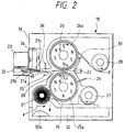
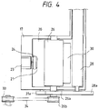
- a separating apparatus 18 will be explained with Figs. 2 to 5, 10 and 11.
- the separating apparatus 18 has a frame 19 within which a mesh filter 20 made of non-magnetic material (for example, non-magnetic stainless steel wires, non-magnetic brass wires, nylon fibers or the like) is arranged along a direction substantially perpendicular to a gravity acting direction (i.e., at an inclination angle of 0° with respect to a horizontal plane).
- a mesh filter 20 made of non-magnetic material (for example, non-magnetic stainless steel wires, non-magnetic brass wires, nylon fibers or the like) is arranged along a direction substantially perpendicular to a gravity acting direction (i.e., at an inclination angle of 0° with respect to a horizontal plane).
- Sleeves 25, 26 for example, made of aluminum
- each magnet roller 25a, 26a has N poles and S poles alternately arranged.
- the sleeves 25, 26 are rotated in directions shown by arrows a, b in Fig. 2. That is to say, the sleeves 25, 26 are rotated in opposite directions.
- the rotation of the sleeve 25 the residual matter adhered to a surface of the sleeve 25 is shifted in the same direction as the rotational direction of the sleeve 25.
- the rotation of the sleeve 26 the magnetic toner adhered to a surface of the sleeve 26 is shifted in the same direction as the rotational direction of the sleeve 26.
- a convey screws 27, 28 for conveying the residual matter serves to convey the magnetic toner and the foreign matters collected in the cleaning device 5 to the separating apparatus 18, and a convey screw 28 for conveying the toner serves to convey the magnetic toner (from which the foreign matters were removed) to the hopper portion 3 of the developing device 2.
- a doctor blade 29 serves to regulate a thickness of a layer of the residual matter adhered to the sleeve 25, and a scraper blade 30 serves to scrape the magnetic toner adhered to the sleeve 26 and to guide the scraped toner to the convey screw 28.
- the mixture of the magnetic toner and the foreign matters removed from the image bearing member 1 by the cleaning device 5 is supplied to the proximity of the sleeve 25 in the separating apparatus 18 by means of the convey screw 27. Then, the mixture is adhered to the surface of the sleeve 25 to be conveyed upwardly by the rotation of the sleeve 25. That is to say, the mixture is sent to the separating zone X.
- the foreign matter such as paper powder is non-magnetic
- the foreign matter since it is mixed with the magnetic toner when the residual matter is removed from the image bearing member, the foreign matter is adhered to the surface of the sleeve 25 together with the magnetic toner.
- a thickness of a layer of the mixture of the magnetic toner and the foreign matters adhered to the sleeve 18 is regulated by the doctor blade 29, and the mixture is sent to the separating zone X where the sleeves 25, 26 are opposed to each other.
- the relation between the magnetic poles S25 and N26 at the separating zone X is N26 > S25.
- the mixture sent to the separating zone X by the sleeve 25 is flying from the surface of the sleeve 25 toward the surface of the sleeve 26 under the action of magnetic fields formed by the magnet rollers 25a, 26a.
- the mesh filter 20 between the sleeves 25, 26 since there is the mesh filter 20 between the sleeves 25, 26, only the magnetic toner having small particle diameter can pass through the mesh of the mesh filter 20 , and the foreign matters such as paper powders each having particle diameter remarkably greater than that of the magnetic toner cannot pass through the mesh filter 20.
- the mesh of the mesh filter 20 (preferably, 150 ⁇ m (#100) to 37.5 ⁇ m (#400)) has an opening greater than the particle diameter of the magnetic toner (average particle diameter of 5 to 20 ⁇ m) by several times, the magnetic toner can smoothly pass through the mesh of the filter.
- the foreign matter caught by the mesh of the filter 20 since vibration is applied to the filter 20 by vibration applying means to be explained later.
- the foreign matter caught by the filter 20 can be dropped by the vibration.
- the magnetic toner which has been removed from the foreign matter is fed to the hopper 3 in which the non-used toner to be mixed with the non-used toner for reuse.
- the mesh filter 20 is pinched between flexible sheets 21 at its one end and is held together with the flexible sheets by the frame 19 of the separating apparatus 18 via a support member 22.
- a drive motor 23 to which an eccentric cam (vibration applying means) 24 for applying the vibration to the mesh filter 20 is connected is attached to the support member 22.
- the cam 24 connected to the drive motor 23 is contacted with one of the flexible sheets 21 so that the vibration is applied to the flexible sheets 21 by rotation of the eccentric cam 24 when the motor 23 is driven, with the result that the vibration is transmitted to the mesh filter 20 through the flexible sheets 21.
- Upper and lower sleeves 26, 25 incorporating magnets (magnetic force generating means) 26a, 25a therein are arranged above and below the mesh filter 20, respectively.
- the driving force from a drive source M of the image forming apparatus is transmitted to drive gears 26a, 25a of the upper and lower sleeves 26, 25 via a drive belt 34 extending between a drive pulley 33 of the image forming apparatus and a drive pulley 26b of the separating apparatus.
- the sleeves 25, 26 are rotated in directions shown by the arrows a, b in Fig. 2, respectively.
- a relation between magnetic poles N26 and S25 at the separating zone X where the upper sleeve 26 is opposed to the lower sleeve 25 with the interposition of the mesh filter 20 is set to N26 > S25.
- a magnet 35 opposed to a magnetic plate 36 with the interposition of the mesh filter 20 is arranged in a communication passage 45 between the separating zone X and a vibration applying portion 21a (i.e., contact portion between the flexible sheet 21 and the eccentric cam 24 connected to the drive motor 23), thereby creating a concentrated magnetic field.
- a vibration applying portion 21a i.e., contact portion between the flexible sheet 21 and the eccentric cam 24 connected to the drive motor 23
- the driving force from a drive source 40 of the image forming apparatus is transmitted to convey screws 27, 28 (for conveying the toner) via a screw drive gear (not shown) meshed with the sleeve drive gear 25a (Fig. 3) and a screw drive gear 28a (Fig. 4) meshed with the sleeve drive gear 26a.
- the convey screws 27, 28 are rotated in directions shown by the arrows c, d in Fig. 2, respectively.
- the convey screw 27 serves to convey the toner (including foreign matters such as paper powder, dust and the like) collected by the cleaning device 10 to the separating apparatus 18, and the convey screw 28 serves to convey the toner from which the foreign matters were separated to the developing device 7 including the hopper portion 8.
- a brush (foreign matter collecting means) 31 serves to scrape the foreign matter adhered to the surface of the lower sleeve 25 together with the residual toner into a collecting portion 32.
- the driving force from the drive source 40 of the image forming apparatus is transmitted to the brush 31 through a drive gear 31a drivingly connected to the sleeve drive gear 25a via an idler gear (not shown) so that the brush 31 is rotated in a direction shown by the arrow e in Fig. 2 (same as the rotational direction of the lower sleeve 25) at a low speed.
- the toner collected from the photosensitive drum 4 by the cleaning device 10 is supplied to the lower sleeve 25 of the separating apparatus 18 by means of the convey screw 27.
- the collected toner includes the foreign matters such as paper powder, dust and the like.
- the collected toner is adhered to the lower sleeve 25 by the magnetic force, so that, as the sleeve 25 is rotated, the toner is conveyed upwardly. Meanwhile, a thickness of the toner layer adhered to the lower sleeve is regulated by the doctor blade 29 to a predetermined thickness. In this way, the collected toner is sent to the separating zone X where the sleeves 25, 26 are opposed to each other with the interposition of the mesh filter 20.
- the magnetic relation between the magnetic pole N26 of the upper sleeve 26 and the magnetic pole S25 of the lower sleeve 25 at the separating zone X is N26 > S25.
- the collected toner (magnetic toner) sent to the separating zone X by the lower sleeve 25 is effectively attracted by the concentrated magnetic force extending from the magnetic pole S25 of the lower sleeve 25 to the magnetic pole N26 of the upper sleeve 26, with the result that only the magnetic toner is forcibly pulled upwardly toward the upper sleeve 26 through the mesh filter 20 in opposition to the gravity force, thereby adhering the toner to the upper sleeve 26. In this way, the magnetic toner is separated from the foreign matters.
- the mesh filter 20 has openings 20a each having a dimension greater than a diameter of the toner particle by several times (preferably, each opening has a size of 150 ⁇ m (#100) to 37.5 ⁇ m (#400)).
- each opening has a size of 150 ⁇ m (#100) to 37.5 ⁇ m (#400)).
- the toner can smoothly path through the mesh filter.
- the time goes on, since the aggregated toner lumps are accumulated in the openings of the mesh filter 20 not to pass through the filter (particularly, under a high humidity condition), thereby causing a so-called filter jam.
- the filter 20 is vibrated (preferably, with frequency of 50 Hz or more and amplitude of about 0.2 to 4.0 mm) in a substantially vertical direction through the thin flexible sheets 21 (21a, 21b) (preferably, having a thickness of about 0.05 to 0.2 mm) by the eccentric cam 24 connected to the drive motor 23.
- the toner lumps caught by the filter 20 are decomposed by the vibration of the filter to eliminate the filter jam, so that the toner can easily be separated from the filter 20 (refer to Figs. 10 and 11).
- the flexible sheets 21a, 21b pinching one end of the filter 20 near the vibration applying position are thin, they can be well restored from the flexure caused by the vibration.
- the flexible sheets 21 are finely vibrated to transmit the vibration to the filter 20, thereby effectively vibrating the mesh filter 20 without deforming the filter.
- the flexible sheets 21a, 21b are thin layers having a thickness of about 0.05 to 0.2 mm, even when the flexible sheets are vibrated, vibration noise is very small, and, thus, the noise does not leak to outside.
- the toner is forcibly separated and conveyed by the magnetic force in opposition to the gravity force, the toner particles deviated from the magnetic field during the conveyance of the toner are floating in the frame of the separating apparatus.
- the floating toner can be prevented from leaking to outside.
- the separating zone X is spatially communicated with the vibration applying portion 21c, there is a danger of entering the floating toner into the vibration applying portion 21c through the communication passage 45.
- the floating toner is caught by the concentrated magnetic field generated by the magnet 35 and the magnetic plate 36 opposed to each other with the interposition of the mesh filter 20 within the communication passage 45, the floating toner is prevented from reaching the vibration applying portion 21c. Further, as the separating time goes on, although an amount of the toner adhered to the magnet 35 and the magnetic plate 36 is gradually increased, since the toner consists of toner particles each having a diameter of about 10 ⁇ m, the connecting condition between the toner particles has versatility. Thus, even if the toner particles adhered to the magnet 35 or the magnetic plate 36 are contacted with the mesh filter 20, the vibration of the filter 20 is not damped, and, thus, the vibration generated by the drive motor 23 as the vibration applying means can effectively be transmitted to the mesh filter 20.
- the toner conveying force due to the magnetic force is sufficiently greater than the weight of the toner particle itself, the toner can easily be conveyed upwardly to be adhered to the upper sleeve 26.
- the toner including the foreign matters is conveyed upwardly in opposition to the gravity force through the mesh filter 20 to separate the foreign matters from the magnetic toner.
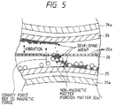
- the separated foreign matters 32a such as paper powder, dust and the like are adhered to the undersurface of the mesh filter 20.
- the mesh filter 20 is vibrated, the foreign matters are dropped from the filter by their own weights. Therefore, the foreign matters can effectively be separated from the toner, and the filter jam can be prevented continuously (Fig. 5).
- the toner (from which the foreign matters were separated) adhered to the upper sleeve 26 is conveyed downstreamly as the sleeve 26 is rotated, and is scraped from the surface of the sleeve 25 by the scraper blade 30, and the scraped toner is conveyed out of the separating apparatus 18 by the convey screw 28. Then, the toner is conveyed to the developing device 7 including the hopper portion 8 to be re-used in the development.
- the foreign matters separated from the magnetic toner at the separating zone X and dropped from the mesh filter are dropped onto the lower sleeve 25 and then are conveyed together with the residual toner (not flying toward the upper sleeve) as the lower sleeve is rotated. Then, the foreign matter is scraped from the lower sleeve 25 by the non-magnetic brush 31 arranged at a downstream side of the separating zone X in the toner conveying direction. Since the non-magnetic brush 31 is urged against the sleeve 25 with weak pressure, the foreign matters adhered to the sleeve 25 with a weak force can be scraped from the sleeve.
- the residual toner not separated at the separating zone X is adhered to the sleeve 25 by the magnetic force, the residual toner is not scraped by the brush 31 but is further conveyed downstreamly for preparation for the next separation. Thus, the toner is almost not collected in the collecting portion 32, and, only the foreign matters 32a are collected in the collecting portion 32.
- the filter 20 is formed as a stainless steel mesh filter, and each opening thereof has a dimension of about 75 ⁇ m (#200). Further, a widthwise length of the filter 20 is about 70 mm, a longitudinal length of the filter is about 40 mm, and a thickness of the filter is about 0.1 mm.
- the sleeves 25, 26 are made of aluminium and each has an outer diameter of about 20 mm.
- An outer diameter of each of the magnets 25a, 26a incorporated into the sleeves 25, 26 is 17.6 mm, and a distance between the sleeves 25 and 26 is about 3 mm.
- the S25 pole has about 650 gauss and N26 pole has about 1000 gauss. From the view point of developing ability and image quality, it is preferable that a weight average particle diameter (D4) of the toner is 3 to 12 ⁇ m (preferably, 3 to 10 ⁇ m, and more preferably, 3 to 8 ⁇ m).
- the grain size distribution of the toner can be measured by various method, in the present invention, it was measured by using a Coaltar counter.
- a Coaltar counter TA-II manufactured by Coaltar Co.
- interfaces manufactured by Nikkaki Co. in Japan
- a personal computer CX-l manufactured by Canon Co. in Japan
- Aqueous solution including NaCl of 1% prepared by using first class sodium chloride was used as electrolyte.
- surface-active agent preferably, alkyl benzene sulfonate
- sample to be measured of 2 to 20 mg was also added to the electrolytic solution.
- the electrolytic solution including the sample suspension was subjected to the dispersing treatment for about 1 to 3 minutes by using a supersonic dispersing device. Thereafter, the volume of the toner and the number of toner particles were measured by the Coaltar counter TA-II using an aperture of 100 ⁇ m, thereby calculating the volume distribution and number distribution of toner particles of 2 to 40 ⁇ m. Thereafter, regarding the present invention, the weight average diameter (central value of each channel is used as a representative value of each channel) of weight reference sought from the volume distribution and standard deviation thereof, and a length average diameter of number reference sought from the number distribution and standard deviation thereof were determined.
- a control portion 37 comprises a CPU, a ROM, a RAM and the like.
- the control portion 37 controls the drive motor (vibration applying means) 23 and the main motor 40 for driving the image forming apparatus via motor drivers 38, 39.
- the motors 23, 40 are controlled by the control portion 37 at timings shown in Fig. 7.
- the mesh filter 20 alone is vibrated by the drive motor 23, and the other portions of the separating apparatus 18 and the entire image forming apparatus are driven by the main motor 40.
- the collected toner which has already been conveyed to the separating zone X when the main motor 40 is stopped is pulled upwardly by the magnetic field generated by the sleeves 25, 26 (now stopped) opposed to each other with the interposition of the mesh filter 20.
- the drive motor 23 is controlled so that it is stopped when the predetermined time period is elapsed after the main motor 40 was stopped.
- the mesh filter 20 is vibrated by the drive motor 23 driven within the above-mentioned predetermined time period, thereby separating the upwardly pulled toner or decomposing the aggregated toner lumps. Accordingly, the toner is not accumulated on the mesh filter 20, and, thus, the filter jam does not occur even when the separating apparatus is left as it is for a long time.
- the control portion 37 will be further explained.
- the control portion 37 serves to control the entire image forming apparatus and includes a CPU such as a microprocessor, a ROM for storing a control program and various data, and a RAM for temporarily storing various data and adapted to be used as a work area for the CPU.
- the control portion 25 receives signals from a group 50 of sensors including a sheet jam detection sensor (jam sensor). Further, the control portion 25 can control various processes such as an exposure process 70 (optical reading system 8), charge process 71 (charge means 7), development process 72 (developing device 2), transferring process 73 (transfer means 7) and fixing process 74 (fixing device 12), conveyance system 75 (sheet supply portion 10, sheet re-supply portion 16), and the separating device 18.
- the image forming operation means an operation that the photosensitive drum 1 is being rotated. That is to say, the pre-rotation of the photosensitive drum 1 is normally effected by the main motor 40. Then, while the photosensitive drum 1 is being rotated, the photosensitive drum is subjected to the above-mentioned charge process, exposure process, development process, transferring process and cleaning process successively. Thereafter, the post-rotation of the photosensitive drum 1 is normally effected, and then, the drum is stopped.
- the image forming operation means the above continuous rotation of the photosensitive drum 1. Incidentally, the pre-rotation and the post-rotation are often omitted.
- the separating apparatus 18 (and accordingly, the sleeves 25, 26) except for the mesh filter 20 is driven and stopped in synchronous with the rotation of the photosensitive drum 1.
- the convey screws 27, 28 are driven by the main motor 40 in synchronous with the sleeves 25, 26.
- the driving of the mesh filter 20 of the separating apparatus 18 is started by the drive motor 23 simultaneously with the driving of the photosensitive drum 1 and the separating apparatus 18, the mesh filter 20 is stopped when the predetermined time period is elapsed after the photosensitive drum 1 and the separating apparatus 18 were stopped (for example, in the illustrated embodiment, the predetermined time period ⁇ shown in Fig. 7 is five seconds, and preferably, three seconds).
- the separating apparatus 18, mesh filter 20, photosensitive drum 1 and the like are controlled by the program stored in the ROM of the control portion 37.
- the present invention is not limited to this example, but may be applied to any separating apparatus and the image forming apparatus so long as the filter is stopped when the predetermined time period is elapsed after the separating apparatus was stopped.
- a drive motor 23 for applying the vibration to the mesh filter 20, a main motor 40 of the image forming apparatus, and a drive motor 42 for driving the separating apparatus other than the mesh filter 20 may be provided independently, and these motors 23, 40 and 42 may be controlled by the control portion 37 via respective motor drivers 38, 39 and 41.
- Such a control is effected by the program stored in the ROM of the control portion 37.
- the main motor 40 and the drive motors 23, 42 start to be driven in synchronous with each other in response to a signal from the control portion 37.
- the drive motor 23 is stopped when a predetermined time period (for example, about 1 to 5 seconds) is elapsed after the motors 40, 42 were stopped.
- a predetermined time period for example, about 1 to 5 seconds
- control portion 37 directly controls the exposure process 70, charge process 71, development process 72, transferring process 73, fixing process 74 and conveyance process 75 was illustrated, as mentioned above, it should be noted that these processes are performed by the main motor 40.
- the present invention is not limited to such an example, but may be applied to any cases wherein non-magnetic foreign matters are separated from magnetic toner.
- the present invention is not limited to such an example, but may be applied to color image forming apparatuses wherein a plurality of developing devices containing different color toners are provided and a plural color image (for example, two-color image, three-color image or full-color image) is formed.
- the present invention is not limited to such an example, but may be applied to color image forming apparatuses wherein the photosensitive drum and the process means are formed as a unit which can removably mounted on the image forming apparatus.
- the present invention is not limited to such a copying machine, but may be applied to other image forming apparatus such as a laser beam printer, a facsimile system or a word processor.
- the drive source for the vibration applying means for applying the vibration to the mesh filter is stopped when the predetermined time period is elapsed after the separating apparatus was stopped.
- the filter jam can surely be prevented, thereby always separating the foreign matters from the toner effectively.
- the present invention relates to a separating apparatus for separating a foreign matter from magnetic toner comprising a filter having at least one opening through which the magnetic toner can pass, a vibration generating means for vibrating the filter, a magnetic field generating means for generating a magnetic field for attracting the magnetic toner to pass it through the filter, and a stop means for stopping the vibration generating means when a predetermined time period is elapsed after the separating apparatus was stopped.
Landscapes
- Life Sciences & Earth Sciences (AREA)
- Engineering & Computer Science (AREA)
- Environmental & Geological Engineering (AREA)
- Sustainable Development (AREA)
- Physics & Mathematics (AREA)
- General Physics & Mathematics (AREA)
- Dry Development In Electrophotography (AREA)
- Cleaning In Electrography (AREA)
- Electrophotography Configuration And Component (AREA)
- Magnetic Brush Developing In Electrophotography (AREA)
Applications Claiming Priority (4)
| Application Number | Priority Date | Filing Date | Title |
|---|---|---|---|
| JP332687/93 | 1993-12-27 | ||
| JP33268793 | 1993-12-27 | ||
| JP6310554A JPH07234621A (ja) | 1993-12-27 | 1994-12-14 | 分離装置及び画像形成装置 |
| JP310554/94 | 1994-12-14 |
Publications (1)
| Publication Number | Publication Date |
|---|---|
| EP0660202A1 true EP0660202A1 (de) | 1995-06-28 |
Family
ID=26566367
Family Applications (1)
| Application Number | Title | Priority Date | Filing Date |
|---|---|---|---|
| EP94120458A Withdrawn EP0660202A1 (de) | 1993-12-27 | 1994-12-22 | Trenngerät und Bilderzeugungsgerät |
Country Status (3)
| Country | Link |
|---|---|
| US (1) | US5563697A (de) |
| EP (1) | EP0660202A1 (de) |
| JP (1) | JPH07234621A (de) |
Cited By (3)
| Publication number | Priority date | Publication date | Assignee | Title |
|---|---|---|---|---|
| DE19631095A1 (de) * | 1995-08-23 | 1997-04-30 | Fujitsu Ltd | Elektrophotographisches Bilderzeugungsgerät |
| FR2747807A1 (fr) * | 1996-04-22 | 1997-10-24 | Toshiba Kk | Appareil de formation d'image |
| CN107662966A (zh) * | 2017-11-18 | 2018-02-06 | 山东泾之渭环保设备工程有限公司 | 一种纵横交错式多级稀土磁辊 |
Families Citing this family (4)
| Publication number | Priority date | Publication date | Assignee | Title |
|---|---|---|---|---|
| US5722018A (en) * | 1996-08-27 | 1998-02-24 | Xerox Corporation | Vibration reducing mounting system for toner filters |
| JP2000029300A (ja) * | 1998-05-08 | 2000-01-28 | Ricoh Co Ltd | 現像装置およびこれを用いた画像形成装置 |
| US7239667B2 (en) * | 2003-03-18 | 2007-07-03 | Broadcom Corporation | 8 PSK rotationally invariant turbo trellis coded modulation without parallel transitions |
| JP4219358B2 (ja) * | 2005-08-31 | 2009-02-04 | シャープ株式会社 | クリーニング部材及びこれを用いた画像形成装置 |
Citations (6)
| Publication number | Priority date | Publication date | Assignee | Title |
|---|---|---|---|---|
| JPS5627186A (en) * | 1979-08-10 | 1981-03-16 | Canon Inc | Developer collecting unit |
| JPS5720767A (en) * | 1980-07-15 | 1982-02-03 | Iwatsu Electric Co Ltd | Developing apparatus used for copying machine or the like |
| JPS57118287A (en) * | 1981-01-14 | 1982-07-23 | Canon Inc | Regenerator for toner |
| US4389968A (en) * | 1980-05-26 | 1983-06-28 | Canon Kabushiki Kaisha | Toner regenerating device |
| JPH0211913B2 (de) * | 1980-10-30 | 1990-03-16 | Canon Kk | |
| EP0612002A1 (de) * | 1993-02-01 | 1994-08-24 | Canon Kabushiki Kaisha | Wiederaufbereitungsvorrichtung für Entwickler und eine sie verwendende Bilderzeugerungsvorrichtung |
Family Cites Families (4)
| Publication number | Priority date | Publication date | Assignee | Title |
|---|---|---|---|---|
| US4054381A (en) * | 1976-04-05 | 1977-10-18 | Xerox Corporation | Toner filter arrangement |
| CH674883A5 (de) * | 1988-05-06 | 1990-07-31 | Escher Wyss Gmbh | |
| JP3117284B2 (ja) * | 1991-09-08 | 2000-12-11 | 株式会社リコー | 現像装置及び異物除去装置 |
| US5455666A (en) * | 1993-06-29 | 1995-10-03 | Canon Kabushiki Kaisha | Developer extracting apparatus and image forming apparatus using it |
-
1994
- 1994-12-14 JP JP6310554A patent/JPH07234621A/ja not_active Withdrawn
- 1994-12-22 EP EP94120458A patent/EP0660202A1/de not_active Withdrawn
- 1994-12-23 US US08/363,007 patent/US5563697A/en not_active Expired - Fee Related
Patent Citations (6)
| Publication number | Priority date | Publication date | Assignee | Title |
|---|---|---|---|---|
| JPS5627186A (en) * | 1979-08-10 | 1981-03-16 | Canon Inc | Developer collecting unit |
| US4389968A (en) * | 1980-05-26 | 1983-06-28 | Canon Kabushiki Kaisha | Toner regenerating device |
| JPS5720767A (en) * | 1980-07-15 | 1982-02-03 | Iwatsu Electric Co Ltd | Developing apparatus used for copying machine or the like |
| JPH0211913B2 (de) * | 1980-10-30 | 1990-03-16 | Canon Kk | |
| JPS57118287A (en) * | 1981-01-14 | 1982-07-23 | Canon Inc | Regenerator for toner |
| EP0612002A1 (de) * | 1993-02-01 | 1994-08-24 | Canon Kabushiki Kaisha | Wiederaufbereitungsvorrichtung für Entwickler und eine sie verwendende Bilderzeugerungsvorrichtung |
Non-Patent Citations (3)
| Title |
|---|
| PATENT ABSTRACTS OF JAPAN vol. 5, no. 81 (P - 063) 27 May 1981 (1981-05-27) * |
| PATENT ABSTRACTS OF JAPAN vol. 6, no. 212 (P - 151)<1090> 26 October 1982 (1982-10-26) * |
| PATENT ABSTRACTS OF JAPAN vol. 6, no. 84 (P - 117)<962> 22 May 1982 (1982-05-22) * |
Cited By (3)
| Publication number | Priority date | Publication date | Assignee | Title |
|---|---|---|---|---|
| DE19631095A1 (de) * | 1995-08-23 | 1997-04-30 | Fujitsu Ltd | Elektrophotographisches Bilderzeugungsgerät |
| FR2747807A1 (fr) * | 1996-04-22 | 1997-10-24 | Toshiba Kk | Appareil de formation d'image |
| CN107662966A (zh) * | 2017-11-18 | 2018-02-06 | 山东泾之渭环保设备工程有限公司 | 一种纵横交错式多级稀土磁辊 |
Also Published As
| Publication number | Publication date |
|---|---|
| JPH07234621A (ja) | 1995-09-05 |
| US5563697A (en) | 1996-10-08 |
Similar Documents
| Publication | Publication Date | Title |
|---|---|---|
| US5734957A (en) | Image forming apparatus with toner re-use feature | |
| US5481351A (en) | Electrophotographic recording apparatus having improved residual toner cleaning function | |
| US5563697A (en) | Separating apparatus for separating foreign matter from a magnetic toner utilizing a vibration generator and a magnetic field generator | |
| JP2019128441A (ja) | 現像装置およびそれを備えた画像形成装置 | |
| EP0614132B1 (de) | Wiederaufbereitungsvorrichtung für Entwickler und eine diese Vorrichtung verwendende Bilderzeugungsvorrichtung | |
| JPS6022350B2 (ja) | 現像装置 | |
| JP3324723B2 (ja) | 画像形成装置 | |
| US5628406A (en) | Separating apparatus and image forming apparatus | |
| US5532800A (en) | Separating apparatus and electrophotographic image forming apparatus using the same | |
| HK1014768A (en) | Separating apparatus and image forming apparatus | |
| JP3363349B2 (ja) | 画像形成装置 | |
| US11841635B2 (en) | Developing device | |
| JPH1124337A (ja) | 画像形成条件設定方法 | |
| EP0612002B1 (de) | Wiederaufbereitungsvorrichtung für Entwickler und eine sie verwendende Bilderzeugungsvorrichtung | |
| JPH06258940A (ja) | 電子写真記録装置の現像装置 | |
| JPH0558195B2 (de) | ||
| JP3110596B2 (ja) | 分離装置及び画像形成装置 | |
| JPH09197828A (ja) | 現像装置 | |
| JPH04330474A (ja) | 現像装置 | |
| JP3674281B2 (ja) | 現像装置 | |
| JPH03175472A (ja) | 画像形成装置 | |
| JPH04330470A (ja) | 現像装置 | |
| JPH09166913A (ja) | 画像形成装置 | |
| JPH07163944A (ja) | 分離装置及び画像形成装置 | |
| JPH11282253A (ja) | クリーナレス画像形成装置 |
Legal Events
| Date | Code | Title | Description |
|---|---|---|---|
| PUAI | Public reference made under article 153(3) epc to a published international application that has entered the european phase |
Free format text: ORIGINAL CODE: 0009012 |
|
| AK | Designated contracting states |
Kind code of ref document: A1 Designated state(s): DE FR GB IT |
|
| 17P | Request for examination filed |
Effective date: 19951114 |
|
| 17Q | First examination report despatched |
Effective date: 19951219 |
|
| GRAP | Despatch of communication of intention to grant a patent |
Free format text: ORIGINAL CODE: EPIDOSNIGR1 |
|
| STAA | Information on the status of an ep patent application or granted ep patent |
Free format text: STATUS: THE APPLICATION IS DEEMED TO BE WITHDRAWN |
|
| 18D | Application deemed to be withdrawn |
Effective date: 20031118 |
|
| REG | Reference to a national code |
Ref country code: HK Ref legal event code: WD Ref document number: 1014768 Country of ref document: HK |