EP0660258A2 - Dispositif de pointage électronique - Google Patents
Dispositif de pointage électronique Download PDFInfo
- Publication number
- EP0660258A2 EP0660258A2 EP94309434A EP94309434A EP0660258A2 EP 0660258 A2 EP0660258 A2 EP 0660258A2 EP 94309434 A EP94309434 A EP 94309434A EP 94309434 A EP94309434 A EP 94309434A EP 0660258 A2 EP0660258 A2 EP 0660258A2
- Authority
- EP
- European Patent Office
- Prior art keywords
- pressure
- point
- elastic member
- contact surface
- pointing device
- Prior art date
- Legal status (The legal status is an assumption and is not a legal conclusion. Google has not performed a legal analysis and makes no representation as to the accuracy of the status listed.)
- Granted
Links
Images


Classifications
-
- G—PHYSICS
- G06—COMPUTING OR CALCULATING; COUNTING
- G06F—ELECTRIC DIGITAL DATA PROCESSING
- G06F3/00—Input arrangements for transferring data to be processed into a form capable of being handled by the computer; Output arrangements for transferring data from processing unit to output unit, e.g. interface arrangements
- G06F3/01—Input arrangements or combined input and output arrangements for interaction between user and computer
- G06F3/03—Arrangements for converting the position or the displacement of a member into a coded form
- G06F3/033—Pointing devices displaced or positioned by the user, e.g. mice, trackballs, pens or joysticks; Accessories therefor
- G06F3/038—Control and interface arrangements therefor, e.g. drivers or device-embedded control circuitry
-
- G—PHYSICS
- G04—HOROLOGY
- G04G—ELECTRONIC TIME-PIECES
- G04G21/00—Input or output devices integrated in time-pieces
-
- G—PHYSICS
- G06—COMPUTING OR CALCULATING; COUNTING
- G06F—ELECTRIC DIGITAL DATA PROCESSING
- G06F3/00—Input arrangements for transferring data to be processed into a form capable of being handled by the computer; Output arrangements for transferring data from processing unit to output unit, e.g. interface arrangements
- G06F3/01—Input arrangements or combined input and output arrangements for interaction between user and computer
- G06F3/03—Arrangements for converting the position or the displacement of a member into a coded form
- G06F3/041—Digitisers, e.g. for touch screens or touch pads, characterised by the transducing means
- G06F3/0414—Digitisers, e.g. for touch screens or touch pads, characterised by the transducing means using force sensing means to determine a position
-
- G—PHYSICS
- G06—COMPUTING OR CALCULATING; COUNTING
- G06F—ELECTRIC DIGITAL DATA PROCESSING
- G06F3/00—Input arrangements for transferring data to be processed into a form capable of being handled by the computer; Output arrangements for transferring data from processing unit to output unit, e.g. interface arrangements
- G06F3/01—Input arrangements or combined input and output arrangements for interaction between user and computer
- G06F3/048—Interaction techniques based on graphical user interfaces [GUI]
- G06F3/0487—Interaction techniques based on graphical user interfaces [GUI] using specific features provided by the input device, e.g. functions controlled by the rotation of a mouse with dual sensing arrangements, or of the nature of the input device, e.g. tap gestures based on pressure sensed by a digitiser
- G06F3/0488—Interaction techniques based on graphical user interfaces [GUI] using specific features provided by the input device, e.g. functions controlled by the rotation of a mouse with dual sensing arrangements, or of the nature of the input device, e.g. tap gestures based on pressure sensed by a digitiser using a touch-screen or digitiser, e.g. input of commands through traced gestures
Definitions
- the present invention relates to a device for generating a signal indicative of the position at a point on a surface to which pressure is applied. More particularly, but not exclusively, the invention relates to an electronic screen pointing device to assist in inputting data into personal computers, or to select a function in digital watches.
- PCs personal computers
- work stations are conventionally performed with the use of keyboards as a primary method of inputting data
- pointing devices as an assisting device for data entry.
- Pointing devices are used, for example, to specify a position of a cursor mark within a display screen, and fall broadly into the following two categories.
- These devices are primarily static devices.
- an external input member is needed to correspond with the positions on a display screen, and a position is specified by specifying an area on the external input member.
- Input operations are performed by touching a transparent electrode on the display screen in the touch screen type, and by contacting a plate type input device with a pen type device, in the tablet type.
- the device is able to move a cursor mark on a screen in terms of the pulsed data derived from planar movements of the pointing device, whose movement vectors (transfer vector per unit time) are input into a computer by transforming the linear movements into digitized pulse data.
- the first type of pointing devices suffers from the disadvantage that the device itself is complex and expensive, and is not easily made compact because of the nature of the device structure itself.
- the touch screen structure incorporates a transparent electrode on top of a display screen attached to a fixed size apparatus, thus it is not suitable for making the pointing device alone compact.
- the tablet type device operates on a one-to-one relationship between the screen and the touching area, and they too are not suitable for making a compact apparatus.
- a mouse requires a certain amount of space for moving of a mouse casing on a flat surface, as well as two encoders for detecting the x- and y-components of a movement vector.
- a tracker-ball has a moving ball and a fixed main body, so that the space for moving the main body is not required; however, it too requires two encoders for detecting the x- and y-components of a movement vector.
- wrist watches capable of not only displaying time but also capable of performing various computational tasks, and inputting, memorizing and displaying data.
- Such wrist watches are provided with a plurality of switch buttons for selecting a function, and keys for inputting data, and such function keys are becoming more numerous, as more functions are offered.
- a tracker ball as the pointing device for selecting a desired function from a screen menu of a computer, but such a device would require not only a rotation member but also two encoders for detecting the x- and y- components of the moving direction. Therefore, such a cursor moving device would not be applicable as a pointing device for such devices as a wrist watch which needs to be small.
- a switch device may also be possible to provide a switch device to display positive and negative directions on the x- and y-axes, and to move a cursor according to the display.
- a switch device would still require moving parts such as springs and contacts, and is vulnerable to loss of reliability when the parts are miniaturized or their numbers are increased.
- a general object of the present invention is to present an electronic pointing device having a long-term service reliability, and which can be miniaturized and operated without involving a mechanical rotating device.
- a device for generating a signal indicative of the position of a point on a surface to which pressure is applied the device being characterised by comprising a body having a protruding contact surface; pressure sensing means spaced apart from the contact surface and for sensing pressure applied to the contact surface; and computing means responsive to the pressure sensing means for generating a signal indicative of the position of the point on the contact surface to which pressure is applied.
- a first electronic pointing device for specifying a static position on a viewing screen of computing means comprising: an elastic member, having a protruding upper body and a planar bottom surface bonded to a base section by bonding means, for propagation of vibrational pressure signals generated from a pressed point on the protruding upper body; at least three pressure sensing means disposed in the base section for detecting vibrational pressure signals propagated from the pressed point, and outputting position indicator signals in accordance with detected pressure signals; and first computing means for computing projection coordinates of the pressed point, in accordance with the position indicator signals, to define coordinates of the pressed point in terms of a center of the planar bottom section.
- the first pointing device when an operator presses on an exposed surface of the elastic member, vibrational pressures are propagated from the pressed point as the center.
- the intensity of the propagating pressure signals is attenuated in proportion to the square of the distance travelled.
- the pressure signals are detected by the pressure sensing elements disposed in the bottom section.
- the coordinates of the pressed point projected on the bottom surface are computed from the ratios of signals received by the pressure sensors, according to specific formulas.
- the pressed point can then be specified in terms of the orthogonal x- and y- axis of the bottom surface with the origin taken at the center of the bottom surface, and a corresponding position on a display screen can be defined by a suitable marking such as a cursor mark.
- the device structure does not involve moving parts, therefore, a long-term service reliability may be assured. Since the operation of the device involves pressing on the elastic member and does not involve moving of the elastic member itself, the device does not require a large space for its operation. Computation of the projection coordinates can be performed repeatedly at specific time intervals so that the coordinates can be specified on a continual basis.
- a second electronic pointing device comprising: an elastic member, having a protruding upper body and a planar bottom surface bonded to a base section by bonding means, for propagation of vibrational pressure signals generated from a pressed point on the protruding upper body; at least three pressure sensing means disposed in the base section for detecting vibrational pressure signals propagated from the pressed point, and outputting position indicator signals in accordance with detected pressure signals; first computing means for computing projection coordinates of the pressed point, in accordance with the position indicator signals, to define coordinates of the pressed point in terms of a center of the planar bottom section; and second computing means for computing the position indicator signals at specified time intervals, and computing a movement vector for indicating a positional change of the surface point in a given time interval.
- the movement of a pressed point may be defined.
- An operator moves a pressing finger on the surface of the elastic member by an amount and in a direction to move a cursor mark on a display screen.
- vibration pressure signals are generated from the pressed point, and as the pressed point moves on the surface of the elastic member, so do the centers of the propagating signals on the surface.
- the computational process involves a series of pressure points in a given sampling interval. A movement vector is thus computed to move the cursor mark from one position on a display screen to another point on the display screen.
- the second pointing device is capable of specifying a series of moving points on the surface of the elastic body in terms of relative projection coordinates, without requiring moving parts. The long-term service reliability may be thus assured. It is obvious that the second pointing device may share other advantages of the first pointing device such as compactness and ease of operation.
- An optional aspect of the device is that the speed of the movement vector can be computed. If the pressed point is moving rapidly, then the sampling frequency is adjusted such that the movement vector is computed on a finer time scale by sampling the movement vector more frequently.
- the elastic member is adhesively bonded to the base section which houses the pressure sensing elements. This arrangement prevents the pressure being applied directly to the pressure sensing members, and provides higher accuracy of position indication.
- the number of pressure sensing elements can be increased from three to four, and the four elements may be disposed equidistantly from the origin in a four fold symmetry.
- the pressure signals detected by the four elements can be compensated so as to equal each other to define the position of the pressed point more precisely. Also, this arrangement enables the propagation distance along the orthogonal axis to be minimized, compared with the case of three pressure sensing elements, by computational method.
- the three or more pressure sensing elements can be fabricated on a common semiconductor base. This arrangement enables the use of semiconductor technology, and the device can be made small and precisely.
- the pressure signals can be detected by three or more pressure sensing elements housed in respective cavities with the opening facing towards the bottom surface. This arrangement of the elements increases the sensitivity of the device by enabling the detection of minute changes in the internal cavities.
- the cavities may be filled with a liquid like material. This will minimize the attenuation of the pressure signals through transmission in air, and increases the sensitivity of detection.
- each cavity may be connected through an associated pressure transmission means such as a tube to a position sensor so that each pressure sensing element can detect a pressure change within its own associated pressure transmission means, thereby making pressure detection independent of the placement of the position indicators.
- the cavities and the associated pressure transmission tubes may be filled with a liquid like material.
- the pressure transmission tubes may be made of an elastically rigid material, thereby increasing the sensitivity of detection of the pressure signals.
- the cavities and the rigid pressure transmission tubes can be filled with a liquid like material to further increase the sensitivity of detection of the pressure signals.
- the pressure transmission tubes can be directed towards a common point at the center of the bottom section. It is then possible to provide many pressure detection devices in a given area of the bottom section, and contributes to lowering the cost of the device.
- Still another optional aspect of the device is that the surface of the elastic member can be covered over with a material having a higher modulus of elasticity than the elastic member. It is then possible to minimize the propagation of surface pressure waves along the elastic member to increase the signals directed to the position indicators, resulting in higher intensities of the pressure signals at the pressure sensing elements.
- the higher modulus of elasticity surface covering may comprise a large number of small pieces which may be spaced apart.
- the pointing device can be disposed on a hand held casing of an apparatus so as to expose the elastic element on the top surface of the apparatus to form a control surface. This arrangement of the pointing device allows the user to specify coordinates by simply pressing on the elastic element on the pointing device.
- the device can be incorporated in an electronic device having a plurality of functions for performing computational tasks, and displaying the computed results on a display screen.
- the electronic device may be a portable electronic device worn by the user.
- the coordinate specification is achieved by the principle of defining the projection coordinates used in the first pointing device, by simply pressing on the exposed area of the elastic element.
- the pointing device is provided with pressure sensing elements which are biased elements so as to generate output signals in proportion to applied pressure.
- the biasing can be applied equally and/or continually to each of the pressure sensing elements so that the pressure signals detected are compared under the same operating conditions.
- Still another optional aspect of the device is that the biasing is applied periodically, instead of continually, only during a measuring period for achieving conservation of electrical power.
- Still another optional aspect of the device is that the biasing is applied to each of the resistance circuit periodically for achieving conservation of electrical power.
- the biasing is a current pulse for circuit simplicity and conservation of electrical power.
- the contact surface/surface of the elastic member is smaller than an adult's hand. It may be substantially the same size as an adult's index finger tip.
- the position of the point on the contact surface/surface of the elastic member which is pressed may be determined mathematically from the values of different pressures sensed by the sensors of the sensing means, or by a look-up table in which the pressure-representative values associated with each sensor for a given pressed point on the contact surface are stored, and with which the sensed values are compared to find the best match.
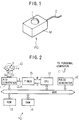
- Figure 1 is a perspective view of a first embodiment of the pointing device of the present invention.
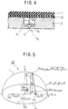
- Figure 2 is a block circuit diagram of the first embodiment.
- Figure 3A shows a perspective view of a partial cut-away section of the position sensor
- Figure 3B shows the position indicators in relation to the pressure sensing elements.
- Figure 4 is an enlarged cross sectional view of the planar bottom section having a position sensor including a bonding interface between an elastic rubber and a semiconductor base.
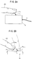
- Figure 5 is an illustration for explaining the principle of determination of the projection coordinate in terms of the position sensors disposed on the planar bottom section.
- Figure 6A illustrates a static position of the operation of the position sensor.
- Figure 6B shows a finger movement which defines a movement vector.
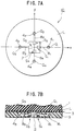
- Figure 7A shows a plan view of the planar bottom section of a variation of the first embodiment of the position sensor.
- Figure 7B shows the bonding interface between the elastic rubber and the semiconductor base.
- Figure 8 shows another variation of the first embodiment of the position sensor.
- Figure 9 shows another variation of the first embodiment of the position sensor.
- Figure 10 is a front view of a computer showing a cursor movement on a display screen in terms of the x- and y-components of a movement vector u.
- Figure 11 shows a second embodiment of the pointing device of the present invention.
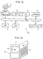
- Figure 12 is a block circuit diagram of the second embodiment.
- Figure 13 a perspective view of a third embodiment of the pointing device of the present invention.
- Figure 14A shows an off-center protruding body having a low height of a variation of the third embodiment.
- Figure 14B is an off-center protruding body having a high height.
- Figure 15 shows a fourth embodiment of the pointing device incorporated in a wrist watch.
- Figure 16 shows an example of a LCD menu display.
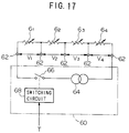
- Figure 17 is a block circuit diagram for biasing the pressure sensing elements in the fourth embodiment.
- Figure 18A is an example applying a constant biasing.
- Figure 18B is an example of a periodic application of biasing.
- Figure 18C is an example of a continual application of biasing during a measuring period.
- Figure 18D is an example of a periodic application of biasing during a measuring period.
- Figure 18E is an example of a continual application of biasing current pulses.
- Figure 18F is an example of a periodic application of biasing current pulses
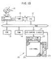
- Figure 19 is a block circuit diagram in the fourth embodiment of the pointing device applicable to a wrist watch.
- Figure 1 is an external view of a pointing device PD.
- the pointing device PD comprises a casing M and a roughly semi-spherical elastic member 1 disposed on a top surface of the casing M.
- a cord C is provided through a side surface of the casing M for transmitting operational data from the pointing device for specifying coordinates to a personal computer and other data processing devices. Details will be explained later.
- a position sensor 10 is provided on the base 2 of the semi-spherical elastic member 1, as shown in Figure 3, and performs a function of computing projection coordinates of a pressed point generated on the elastic member 1.
- a partial cut-away view of the position sensor 10 shows an interior configuration of the position sensor 10.
- the position sensor 10 comprises piezo-electric pressure sensing elements S1 to S4 and an elastic member 1 of a roughly semi-spherical shape.
- the elastic member 1 has a perfectly semi-spherical shape, although other shapes are possible.
- the piezo-electric pressure sensing elements (the elements, for short), S1 ⁇ S4 are disposed on the plane surface L of a semiconductor base 2 of the elastic member 1, and generate electrical voltages, V1 ⁇ V4 in proportion to the applied pressure. Further details of the pressure sensing device will be given later.
- the elements S1 ⁇ S4 correspond to position indicators Q1 ⁇ Q4, and their coordinates (x, y) are given with respect to the origin (0, 0) of the plane surface L and a radius r of the elastic member 1.
- Q1 ⁇ Q4 are represented by the following coordinates defined by x- and y-axes: (a, 0), (0, a), (-a, 0), and (0, -a) where r>a>0 and the positive directions are in the direction of the arrows on the x- and y-axes.
- the four points Q1 ⁇ Q4 are equidistant from the origin (0, 0) by an amount "a".
- a base section of the position indicator shown in Figure 4, comprises a semiconductor base 2 bonded to the elastic member 1 with an intervening bonding layer 3.
- the element S1 is fabricated within a small cavity 41 formed in the base 2 to correspond with the position indicator Q1.
- the element S1 comprises a diaphragm member (a thin film of several tens of ⁇ m thickness) 51, and a strain gage 61 fabricated on top of the diaphragm member 51.
- the element S1 is fabricated using a known semiconductor etching technique, and in particular, the strain gauge is a piezo-electric device having a p-type resistive layer made by selective diffusion of impurities (such as boron) in the base 2.
- impurities such as boron
- the elements S2 ⁇ S4 are fabricated on the base 2, and serve as position indicators Q2 ⁇ Q3 by generating a voltage proportional the applied pressure.
- the position sensor 10 generates position information as follows.
- pressure waves are generated and propagated through the elastic member 1 as elastic waves to apply vibrational forces on the cavities 41 ⁇ 44 corresponding to the position indicators Q1 ⁇ Q4.
- the strain gauges 61 ⁇ 64 experience strains in response to the pressure differentials (caused by the difference in the pressure in the cavity interior and the outside atmospheric pressure) exerted on the gauges 61 ⁇ 64 through the opening 7. Pressure variations cause the resistance of the gauges 61 ⁇ 64 to vary accordingly.
- the terminal ends of the gauges 61 ⁇ 64 are coated with vapor deposited aluminum for providing external electrical connections for processing the output resistance signals by known circuitry. The result is a generation of the voltages V1 ⁇ V4 in proportion to the signal strength from position indicators Q1 ⁇ Q4.
- the cavities 41 ⁇ 44 can be filled with a liquid medium having a low coefficient of thermal expansion (e.g. water, alcohol), or liquid-like material (e.g. gelatin).
- a liquid medium having a low coefficient of thermal expansion e.g. water, alcohol
- liquid-like material e.g. gelatin
- Figure 5 is a simplified version of the position sensor shown in Figure 3, and the details have been omitted for the purpose of illustrating only the principle of projection coordinates determination.
- vibrational forces are generated at a point P n of the elastic member 1 as a result of arterial blood pressures acting through the finger tip.
- the point P n is taken as the effective center point of the generation of vibrational forces.
- the point P n is taken as the center point of application of the pressed point generated by the finger 40.
- the vibrational forces are propagated as elastic pressure waves through the elastic member 1.
- the pressure waves are attenuated in proportion to a square of the distance travelled, and are detected by the elements S1 ⁇ S4 which produce corresponding electrical voltages V1 ⁇ V4.
- Equation (1) the point P n (x,y) on the spherical surface of the elastic member 1 is given from Equation (1) by: From Equations (1) and (2), the distances between the point Pn and the position indicators Q1 ⁇ Q4 are given respectively by the following equations.
- P n Q 1 ⁇ a 2-2 ax n + r 2
- P n Q 2 ⁇ a 2-2 ay n + r 2
- P n Q 3 ⁇ a 2+2 ax n + r 2
- P n Q 4 ⁇ a 2+2 ay n + r 2
- the voltages V1 ⁇ V4 generated by the elements S1 ⁇ S4 are inversely proportional to a square of the propagation distance.
- the voltages V1 ⁇ V4 are given by the equality equations as follows.
- Equation (4) the coordinates (x, y) of the point P n (x,y) are given by the following equations.
- x n ( V 1- V 3) ⁇ ( a 2+ r 2) 2 a(V 1+ V 3)
- y n ( V 2- V 4) ⁇ ( a 2+ r 2) 2 a(V 2+ V 4)
- the coordinates of the point Pn can be determined from the values of the output voltages V1 ⁇ V4 from the elements S1 ⁇ S4.
- the coordinates of the point P n thus obtained correspond, in effect, to the coordinates of point P' n , shown in Figure 5, which is a vertical projection of the point P n onto the plane surface L (corresponding to the position indicators Q1 ⁇ Q4 of the elements S1 ⁇ S4).
- the coordinate x n are calculated from the voltages V1 to V3 generated by the elements S1 to S3 located on the x-axis, independently of the coordinate y n calculated from the voltages V2, V4 generated by the elements S2, S4 located on the y-axis.
- the method of computation assure that there will be no mutual interference. This is explained further in the following.
- Equation (4) it can be seen by analyzing Equation (4) in detail that only three voltage values from the elements S1 ⁇ S4 are needed to obtain the coordinates x n , y n , but with this method, the computation of the last coordinate based on the remaining voltage value is affected by the preceding three voltage values. For example, to obtain the coordinates x n , y n based only on the output voltages from the elements S1 ⁇ S4, the coordinate x n is calculated first from the voltages V1, V3, then substituting this value of x n in Equation (4), and using the value of voltage V2, the value of y n can be calculated. But, this method of calculating the coordinate y n involves the voltages V1 ⁇ V3, and if there are differences in the output characteristics among the elements, accurate determination of the final coordinate cannot be performed.
- the roughly semi-spherical elastic member 1 is assumed to be a perfect semi-circular body, i.e., it is assumed that a sphere is sliced exactly in half through its center.
- the elastic member be a low protrusion shape as illustrated in Figure 14A.
- the position indicators Q1 ⁇ Q4 based on the elements S1 ⁇ S4 will be given as: Q1 (a, 0, ⁇ z) Q2 (0, a, ⁇ z) Q3 (-a, 0, ⁇ z) Q4 (0, -a, ⁇ z).
- the vibrational forces generated at the point P n are attenuated in proportion to a square of the distances, and the voltages V1 ⁇ V4 will be inversely proportional to the square of the distances between the point P n and the respective position indicators.
- a product of the square of a distance given in Equation (6) with the corresponding voltage is equal to that in other position indicators, and as before, the coordinates x n , y n of the point P n will be given by the following equations.
- Equation (8) if the value of ( ⁇ z) is small enough, the quantity ( ⁇ z)2 can be disregarded.
- Equation (8) if the value of (Z a ⁇ z) can be disregarded when the distance between the origin and the position indicators is made as large as possible within the dimension of the radius r.
- Equation (8) becomes virtually the same as Equation (5).
- the method involves a calibration experiment to prepare a table relating the ratios of the output voltages V1 ⁇ V4 generated by applying vibrational forces of known magnitude on a spot on the exposed surface of the elastic member 1. By repeating this process at different points on the exposed surface of the elastic member 1, it is possible to prepare a table relating the positions on the exposed surface to the generated voltages.
- the actual coordinates (x n , y n ) of the point Pn is obtained from the table by finding a ratio of the voltages generated from touching a spot on the exposed surface of the elastic member 1.
- the shape of the elastic member 1 is not restricted to a semi-spherical shape only. Other surface shapes suitable to the user can be chosen without invalidating the method of the present invention.
- the speed vector V ( x n+ 1 - x n ) 2+( y n+ 1 - y n )2 1 Fs
- the pointing device when an average value of the voltages V1 ⁇ V4 exceeds a specific threshold value, the pointing device recognizes that a "clicking" operation has been performed. This situation occurs when a finger 40 pressing on a point on the elastic element 1 increases the touching pressure further. It can be recognized from Equation (5) that the calculation of the coordinates is performed on the basis of the ratio of the voltages V1 ⁇ V4 rather than their absolute values, and therefore, the specified coordinates will not be changed unless the touching point is changed.
- the ability to detect a clicking operation can be used in the same way as is done with a conventional mouse (where clicking is performed by pressing a button on the mouse body). For example, applying relatively liight finger pressure to the elastic member 1 could act to position the cursor in a particular part of the display on a PC monitor which indicates a particular function. If clicking is then performed the function is activated.
- Figure 7A shows a plan view of another form of the position sensor 10.
- Figure 7B is a cross sectional view of the location indicator. Those parts which are the same as in the first embodiment will be given the same reference number, and their explanation will be omitted.
- the position sensor 10 comprises, as before, a cavity 41 associated with a position indicator Q1.
- a hollow tube 81 provided on a side surface of the cavity 41 extends towards the center of the plane surface L and joins with the base 2.
- the cavities 41-44 associated with the position indicators Q1-Q4 are provided which join with the base 2 via the hollow tubes 82 ⁇ 84 extending towards the center of the plane surface L.
- the base 2 has the elements S1-S4 which are connected to the openings of the hollow tubes 81-84.
- the cavities 41-44 and the hollow tubes 81-84 are made separately from the base 2 and should be made of an elastically rigid material 9 such as hard plastics or metals.
- an elastically rigid material 9 such as hard plastics or metals.
- the position indicators 10 illustrated has strain gauges bonded to the position indicators Q1 ⁇ Q4 on the plane surface L to detect the strains produced by the vibrations. But this construction is susceptible to strains produced by minute deformation produced, affecting the output signals directly when the elastic member 1 is pressed with a finger. Therefore, it is preferable to construct the device as shown in Figure 4 so that the elastic waves are detected via the bonding layer 3 and the cavities 4.
- the number of the elements in this embodiment was four, but the device will perform equally effectively with three elements, as mentioned previously.
- the need is to ascertain that the positions indicators are provided on the plane bottom section of a semi-spherical elastic member so as to enable the device to accurately correlate the positions of the elements with the positions on the surface of the elastic member 1.
- the elastic waves generated by the vibrations at point P n are propagated not only to position indicators Q1 ⁇ Q4 but are propagated uniformly in all directions within the elastic member 1. Therefore, there is a disadvantage that the pressure signal strengths V1 ⁇ V4 at the position indicators Q1 ⁇ Q4 are dependent on the magnitude of the vibrations generated at the location P n . Therefore, when the signal strengths are low, the S/N ratio is degraded, i.e. the noise becomes more noticeable.
- the following embodiments relate to devices having improved S/N ratios.
- the present inventors discovered that when a cover member 81 having a higher elastic modulus than that of the elastic member 1 (for example a hard plastic or metal) is used to cover the surface of the elastic member 1, as illustrated in Figure 8, the output voltages V1 ⁇ V4 from the elements S1 ⁇ S4 are increased over those without the covering.
- a cover member 81 having a higher elastic modulus than that of the elastic member 1 for example a hard plastic or metal
- Another advantage of this approach is that the presence of the cover member 81 eliminates direct finger contact on the elastic member 1, and the degradation of the elastic member 1 by finger oil is prevented.
- the propagation coefficient is higher for the elastic waves travelling from the small pieces 82 to the position indicators than those travelling from the exposed elastic surface of the elastic member 1 to the position indicators. Therefore, there is a tendency for the coordinates of the point P n to be selectively defined in favor of those positions of the small pieces 82 projected on the plane surface L. However, because the output signals are higher, this type of device would be effective for those applications where the resolution is not the prime requirement.
- An A/D converter 11 samples the output voltages V1 ⁇ V4 at the sample timing determined by the clock CLK, and converts the analogue voltage signals to digital signals.
- the sampled output voltages V1 ⁇ V4 are placed in sample hold at the clock rate, and are multiplexed with a multiplexer at a rate significantly faster than the clock rate, and converted into digital signals.
- the digital signals are supplied via an interface (not shown) and a bus to a CPU (central processing unit) 12.
- a ROM (random access Read Only Memory) 13 stores the programs and other instructions necessary for the CPU 12.
- a RAM (random access read and write memory) 14 memorizes a coordinate at every clock timing.
- a timer 15 generates the basic clock frequency ⁇ for supplying to CPU 12 as well as outputting a divided clock frequency based on the basic clock frequency ⁇ under the command of the control signal S from the CPU 12.
- a pulse generator 16 is used to generate count pulses corresponding to the movement vector computed by CPU 12 to generate signals to indicate clicking operation, and forwards the generated signals to an external device such as a PC (not shown) via a chord C (refer to Figure 1).
- This pulse generator 16 does not generate count pulses when it is used as the "absolute coordinates" detection type, and the information on the point P' n is supplied directly to the PC.
- CPU 12 computes the coordinates x n , y n in accordance with Equation (5) from the sampled voltages V1 ⁇ V4, and when applicable, subtracts the preceding coordinates x n-1 , y n-1 from the coordinates x n , y n to obtain the values of the x- and y-components for a movement vector during one cycle of the clock CLK.
- CPU 12 also controls the frequency of the clock CLK of the timer 15 by means of the control signal S so that the frequency is reduced to a half, for example, when the movement speed is faster than a specific value, or to double the frequency, for example, when the movement speed is slower than the specific value.
- This type is used to define a static point. It is assumed here that the screen coordinates on the PC screen and the coordinates on the plane surface L of the PD device have been correlated on a one to one basis when the pointing device PD is used as the absolute type.
- the operator places a finger 40 on the surface of the elastic member 1, as illustrated in Figure 6, and presses on the surface.
- the center of the pressed point is defined in terms of a vertical projection point of the pressed point on the plane surface L.
- the pressing operation causes the elastic member 1 to vibrate at the pressed point as the center, and the generated elastic waves are propagated towards the position indicators Q1 ⁇ Q4.
- the elastic waves are detected by the elements S1 ⁇ S4 and are converted into voltages V1 ⁇ V4 and digitized.
- the coordinates x n , y n are calculated on the basis of the digitized data by the CPU 12, and are forwarded towards a PC.
- This operation is repeated for every period of the clock CLK, and successive coordinates are determined.
- the coordinates x n , y n are generated by the position indicator Q1 ⁇ Q4 on the basis of the point on the plane surface L projected by the pressed point on the elastic member 1.
- the results are forwarded to the PC to specify a point on the screen coordinates.
- step 1 the operator presses on a point with a finger 40 (step 1), and moves the finger 40 along the surface in the direction of the vector u (step 2). While watching the PC screen, the operator repeats the steps 1, 2 so as to obtain coincidence between the current cursor mark 30 with the desired point 31.
- This operation performs an action similar to the rotation of the elastic member 1 in the direction of the vector u. It should be noted, however, that the elastic member 1 itself does not actually rotate.
- count pulses and the directional marks corresponding to each movement vector are generated, and are forwarded towards the PC.
- the count pulses indicate the absolute value of the vector
- the marks indicate the direction of the vector to define the magnitude and the direction of the movement needed for the coordinates x n , y n .
- the result is that the cursor mark 30 moves by the amount specified by the movement vectors from the preceding point and arrives at the first new point.
- the second new coordinates x n+2 - x n+1 y n+2 - y n+1 are calculated.
- the count pulses and directional marks are generated to correspond with the second new point, and are forwarded towards the PC. The result is that the cursor mark 30 moves from the first new point to the second new point by the amount and the direction specified by the second movement vectors.
- the operator moves the pressed point on the elastic member 1 so that the cursor mark 30 on the screen moves from one point to a desired point by repeatedly moving the pressed point on the elastic member 1, and thereby generating a number of appropriate movement vectors u to reach the desired point on the screen.
- CPU 12 further controls the frequency division of the clock CLK in the timer 15, by generating a control signal S in accordance with the speed V of the movement vector u obtained in Equation (9).
- the speed V is divided into three ranges such that: 0 ⁇ V ⁇ V min V min ⁇ V ⁇ V max V max ⁇ V where V represents the current speed and V min , V max represent pre-determined threshold speed values.
- CPU 12 determines in which speed range the current speed is operating, and generates the control signal S to control the clock rate of the timer 15. For example, if the current speed is in ( ⁇ ) range, the present clock cycle is doubled; if the speed is in ( ⁇ ) range, the present clock cycle is retained; and if the speed range is in ( ⁇ ) range, the clock cycle is halved.
- Various control techniques are used as needed.
- the above described method of controlling the sampling rate is used to enable following the movement of the pressed point in these embodiments.
- the pointing device PD was made to be a stand-alone device for use with a desk top PC, for example.
- the second embodiment relates to a different type of pointing device, and presents a case of incorporating the pointing device PD within the PC body.
- Figure 11 shows a perspective view of the second embodiment of the pointing device PD of the present invention.
- the pointing device PD is incorporated in a lap-top PC 50 having a display section 17.
- the elastic member 1 is disposed so as to protrude out from the front section of the keyboard 51.
- Figure 12 shows a block circuit diagram for the second embodiment.
- the difference in the circuit configuration between the first embodiment shown in Figure 2 and the second embodiment shown in Figure 12 is that an independent circuit device, a pulse generator 16, is not required, because this function can be provided by the PC 50.
- the cursor mark 30 is shown in the display section 17, and input data are inputted into PC 50 through the keyboards 51.
- CPU 12, ROM 13 and RAM 14 shown in Figure 12 are shared with PC 50. That is, PC 50 performs computations related to defining the coordinates in the first embodiment or the movement vector u in addition to the standard computational requirements of PC 50, thereby specifying the cursor mark 30.
- FIG. 13 is a perspective view of the external appearance according to the third embodiment.
- the pointing device PD is incorporated into a portable electronic device having a display device 17, such as an electronic memo 60.
- the elastic member 1 is provided in the upper section of the key switch assembly 61.
- the electrical configuration of this embodiment is the same as that shown in Figure 12.
- the second and third embodiments of the pointing device PS present an advantage that miniaturization of the pointing device PD has been made possible by eliminating the necessity for having a moving sphere.
- a fourth embodiment of the pointing device PD applied to a wrist watch 20 having a size even smaller than that in the foregoing embodiments will be explained with reference to Figures 15 to 17.
- Figure 15 is a perspective view of the wrist watch 20 having a pointing device PD of the fourth embodiment.
- the wrist watch 20 has a liquid crystal display (LCD) panel 24 (panel for short) which is disposed in the middle of a watch casing M.
- the panel 20 is viewed in the direction A and normally displays time of the day, but can also display a menu for selecting a function.
- An example of a menu is shown in Figure 16.
- the functions shown in this menu are listed in rows, and for any one function, subsequent information are stored in layers below the first layer. A desired function can be selected by means of the cursor mark 30, and a clicking operation brings out the subsequent information in rotation.
- Figure 15 shows an elastic member 1 which comprises a part of the position sensor 10, and is disposed below the panel 24.
- the screen coordinates are specified by pressing and clicking operations on the elastic member 1.
- the electrical configuration of the elements S1 ⁇ S4 of the position sensor 10 will be explained with reference to Figures 17 and 18.
- the strain gauges 61-64 are variable resistors to achieve balancing of the circuit.
- the strain gauges 61-64 correspond with the elements S1 ⁇ S4 and are connected in series, as shown in Figure 17, with output terminals 62 at both ends.
- the ends of the series resistances are connected to a biasing circuit 60.
- the biasing circuit 60 comprises a fixed current circuit 64; a switch 66 for turning an output signal from the circuit 64 on/off; and a switching circuit for turning the switch 66 on when a control signal T becomes a high H.
- the output signal from the fixed current circuit 64 is impressed on the strain gauges 61-64 when the control signal T becomes high H.
- the resistance of a strain gauge changes with changing strains, therefore, when a constant current is flowed through the strain gauges 61-64, the voltages V1 ⁇ V4 between the terminals 62 are proportional to the pressures exiting at the position indicators Q1 ⁇ Q4 and will represent the relative magnitude of the applied pressures.
- Figure 18A shows a constant signal 70 showing a high H during both measurement period and non-measurement period
- Figure 18B shows a pulsed signal 72 during both measurement period and non-measurement period
- Figure 18C shows a signal 72 which shows a constant high H during measurement period
- Figure 18D shows a pulsed signal 76 which becomes high only during measurement period.
- the measurement period refers to a period of detection of elastic vibrations.
- the signal 70 is suitable for high accuracy of position detection.
- the pulsed signal 76 will be suitable.
- signals 72 or 74 would be suitable.
- the strain gauges 61-64 have a constant current flowing, and there is some generation of heat. Therefore, there is a temperature difference when the biasing is applied and when it is not. The temperature difference leads to a slight difference in the resistances, and can cause an error in pressure determinations. If the signal 70 is chosen for the control signal T, the current is flowing through the strain gauges 61-64 even during non-measurement periods, and if measurements are made allowing sometime to elapse for thermal stabilization of the circuit, measurement errors stemming from temperature differences will be extremely low.
- the signal 76 is chosen for the control signal T, the current flows intermittently only during the measurement period, and the thermal generation effect is minimized and power conservation can also be achieved. Further power conservation would be possible by operating the position sensor 10 and its associated circuitry (A/D converter and amplifiers and so on) synchronously with the measurement operation. It can be arranged so that the power is applied to the measuring circuit only when the pulsed signal 76 is high H for further savings in power consumption.
- the constant biasing current from the constant current output circuit 64 can have various waveforms.
- the signals can have sufficiently higher frequencies than either the pulsed signals 72 or 76, as shown in Figure 18E.
- various combinations of signals 70, 72 and 76 can be chosen.
- the pulsed signal 76 is chosen, the period of application of the biasing voltage on the stain gauges 61-64 will be very brief, and the power consumption is also very low.
- the position sensor 10 and its measuring circuits can be operated synchronously with the application of the biasing voltage for power conservation, and only during the duration of the bias application.
- biasing waveform should be compatible with the vibrational pressure changes so as to be within the sampling capability, and also that the central processor is capable of handling the output data.
- FIG 19 shows an electrical configuration of the wrist watch 20.
- the watch circuit has no keyboard 51, and a LCD panel 24 is used instead of the display section 17.
- the control signal T for the biasing circuit 60 shown in Figure 17 is generated by a clock CLK. Therefore, in the biasing circuit 60 in this embodiment, the biasing voltage is applied to the strain gauges 61-64 synchronously with the clock CLK signals.
- a LCD control circuit 21 generates timing signals and display data (to be displayed on the LCD display panel 24) based on the data supplied via bus from CPU 12, and supplies them to the vertical line control circuit 22 and the horizontal line control circuit 23.
- the vertical line control circuit 22 and the horizontal line control circuit 23 are connected to each electrode of the panel 24, and controls the respective vertical or horizontal electrode. The data supplied by CPU 12 are thus displayed on the LCD panel 24.
- the basic clock ⁇ is counted by CPU 12, and the accumulated count is displayed on the panel 24 as time of the day.
- the technique is conventional and will not be described.
- the cursor mark is moved to a desired function according a pre-selected absolute mode or the relative mode.
- the selected function is operated with the use of the position sensor 10.
- the position sensor 10 is capable of performing all the operations required of any electronic devices regardless of the size of the complexity of functions.
- the technique is based on determining a position with three elements. First, three elements are selected from the four elements, and coordinates x n , y n are determined for a point. Next, another three elements are chosen to obtain the coordinates x n , y n . The number of ways of selecting three elements from four elements is four ways given by 4C3, and the remaining two ways will also produce two sets of coordinates x n , y n . The four sets of coordinates thus obtained independently will all be the same if all the elements S1 ⁇ S4 have the same characteristics.
Landscapes
- Engineering & Computer Science (AREA)
- General Engineering & Computer Science (AREA)
- Theoretical Computer Science (AREA)
- Physics & Mathematics (AREA)
- General Physics & Mathematics (AREA)
- Human Computer Interaction (AREA)
- Position Input By Displaying (AREA)
Applications Claiming Priority (6)
| Application Number | Priority Date | Filing Date | Title |
|---|---|---|---|
| JP5320582A JPH07175584A (ja) | 1993-12-20 | 1993-12-20 | ポインティング・デバイス |
| JP32058393A JPH07175586A (ja) | 1993-12-20 | 1993-12-20 | ポインティング・デバイス |
| JP32058293 | 1993-12-20 | ||
| JP320582/93 | 1993-12-20 | ||
| JP320583/93 | 1993-12-20 | ||
| JP32058393 | 1993-12-20 |
Publications (3)
| Publication Number | Publication Date |
|---|---|
| EP0660258A2 true EP0660258A2 (fr) | 1995-06-28 |
| EP0660258A3 EP0660258A3 (fr) | 1998-08-12 |
| EP0660258B1 EP0660258B1 (fr) | 2000-03-08 |
Family
ID=26570134
Family Applications (1)
| Application Number | Title | Priority Date | Filing Date |
|---|---|---|---|
| EP94309434A Expired - Lifetime EP0660258B1 (fr) | 1993-12-20 | 1994-12-16 | Dispositif de pointage électronique |
Country Status (3)
| Country | Link |
|---|---|
| US (1) | US5691747A (fr) |
| EP (1) | EP0660258B1 (fr) |
| DE (1) | DE69423313T2 (fr) |
Cited By (11)
| Publication number | Priority date | Publication date | Assignee | Title |
|---|---|---|---|---|
| EP0782274A1 (fr) * | 1995-12-29 | 1997-07-02 | Eta SA Fabriques d'Ebauches | Unité réceptrice portable avec dispositif de commande actionné à la main |
| WO1998039730A3 (fr) * | 1997-03-03 | 1998-12-23 | Ericsson Telefon Ab L M | Dispositif pour commander un indicateur de position sur un affichage visuel |
| EP1011066A1 (fr) * | 1997-11-21 | 2000-06-21 | Yang Tai-Her | Dispositif de contrôle manuel en forme d'anneau |
| EP1176480A1 (fr) * | 2000-07-27 | 2002-01-30 | Asulab S.A. | Dispositif d'introduction de données dans un objet portable |
| EP1282018A1 (fr) * | 2001-08-03 | 2003-02-05 | Nokia Corporation | Dispositif électronique portable |
| EP1293928A3 (fr) * | 2001-09-17 | 2004-05-12 | Alps Electric Co., Ltd. | Dispositif d'entrée de coordonnées avec surface d'opération non-plate et appareil électronique |
| WO2007026293A3 (fr) * | 2005-08-30 | 2008-05-08 | Koninkl Philips Electronics Nv | Procede de mesure du mouvement relatif d'un objet et d'un dispositif d'entree optique sur une plage de vitesses |
| EP2538306A1 (fr) * | 2011-06-20 | 2012-12-26 | Research In Motion Limited | Dispositif d'entrée par l'utilisateur détectant la pression |
| WO2015123120A1 (fr) * | 2014-02-13 | 2015-08-20 | Microsoft Technology Licensing, Llc | Bouton de pointage ultraplat |
| US9874945B2 (en) | 2014-02-13 | 2018-01-23 | Microsoft Technology Licensing, Llc | Low-profile pointing stick |
| US10627918B2 (en) | 2014-02-13 | 2020-04-21 | Microsoft Technology Licensing, Llc | Low-profile pointing stick |
Families Citing this family (119)
| Publication number | Priority date | Publication date | Assignee | Title |
|---|---|---|---|---|
| US5889670A (en) | 1991-10-24 | 1999-03-30 | Immersion Corporation | Method and apparatus for tactilely responsive user interface |
| US6239785B1 (en) * | 1992-10-08 | 2001-05-29 | Science & Technology Corporation | Tactile computer input device |
| US5734373A (en) | 1993-07-16 | 1998-03-31 | Immersion Human Interface Corporation | Method and apparatus for controlling force feedback interface systems utilizing a host computer |
| US5666138A (en) | 1994-11-22 | 1997-09-09 | Culver; Craig F. | Interface control |
| US6166723A (en) | 1995-11-17 | 2000-12-26 | Immersion Corporation | Mouse interface device providing force feedback |
| US6025832A (en) * | 1995-09-29 | 2000-02-15 | Kabushiki Kaisha Toshiba | Signal generating apparatus, signal inputting apparatus and force-electricity transducing apparatus |
| US5825308A (en) * | 1996-11-26 | 1998-10-20 | Immersion Human Interface Corporation | Force feedback interface having isotonic and isometric functionality |
| US6100874A (en) | 1995-11-17 | 2000-08-08 | Immersion Corporation | Force feedback mouse interface |
| US6061004A (en) * | 1995-11-26 | 2000-05-09 | Immersion Corporation | Providing force feedback using an interface device including an indexing function |
| US6147674A (en) | 1995-12-01 | 2000-11-14 | Immersion Corporation | Method and apparatus for designing force sensations in force feedback computer applications |
| US6028593A (en) | 1995-12-01 | 2000-02-22 | Immersion Corporation | Method and apparatus for providing simulated physical interactions within computer generated environments |
| US6219032B1 (en) | 1995-12-01 | 2001-04-17 | Immersion Corporation | Method for providing force feedback to a user of an interface device based on interactions of a controlled cursor with graphical elements in a graphical user interface |
| US8508469B1 (en) | 1995-12-01 | 2013-08-13 | Immersion Corporation | Networked applications including haptic feedback |
| US6300936B1 (en) | 1997-11-14 | 2001-10-09 | Immersion Corporation | Force feedback system including multi-tasking graphical host environment and interface device |
| US6078308A (en) | 1995-12-13 | 2000-06-20 | Immersion Corporation | Graphical click surfaces for force feedback applications to provide user selection using cursor interaction with a trigger position within a boundary of a graphical object |
| GB2308486A (en) * | 1995-12-21 | 1997-06-25 | Nokia Mobile Phones Ltd | Display apparatus for hand held equipment |
| US6374255B1 (en) | 1996-05-21 | 2002-04-16 | Immersion Corporation | Haptic authoring |
| KR100260760B1 (ko) * | 1996-07-31 | 2000-07-01 | 모리 하루오 | 터치패널을 병설한 정보표시장치 |
| US8120579B2 (en) * | 1996-09-26 | 2012-02-21 | Giv, Llc | Textured cushion for cursor control stick |
| US20070063974A1 (en) * | 1996-09-26 | 2007-03-22 | Slotta Mark R | Textured cushion for cursor control stick |
| US6724369B2 (en) * | 1996-09-26 | 2004-04-20 | Giv, Llc | Textured cushion for keyboard cursor control stick |
| US6956558B1 (en) | 1998-03-26 | 2005-10-18 | Immersion Corporation | Rotary force feedback wheels for remote control devices |
| US6686911B1 (en) | 1996-11-26 | 2004-02-03 | Immersion Corporation | Control knob with control modes and force feedback |
| US6154201A (en) * | 1996-11-26 | 2000-11-28 | Immersion Corporation | Control knob with multiple degrees of freedom and force feedback |
| US6636197B1 (en) | 1996-11-26 | 2003-10-21 | Immersion Corporation | Haptic feedback effects for control, knobs and other interface devices |
| US7489309B2 (en) | 1996-11-26 | 2009-02-10 | Immersion Corporation | Control knob with multiple degrees of freedom and force feedback |
| US6128006A (en) * | 1998-03-26 | 2000-10-03 | Immersion Corporation | Force feedback mouse wheel and other control wheels |
| US5907318A (en) * | 1997-01-17 | 1999-05-25 | Medina; Carlos A. | Foot-controlled computer mouse |
| JP3247630B2 (ja) * | 1997-03-07 | 2002-01-21 | インターナショナル・ビジネス・マシーンズ・コーポレーション | ポインティング・デバイス、携帯用情報処理装置、及び情報処理装置の操作方法 |
| JPH10326146A (ja) * | 1997-05-23 | 1998-12-08 | Wacom Co Ltd | 座標入力用器具 |
| US6292174B1 (en) | 1997-08-23 | 2001-09-18 | Immersion Corporation | Enhanced cursor control using limited-workspace force feedback devices |
| US6252579B1 (en) | 1997-08-23 | 2001-06-26 | Immersion Corporation | Interface device and method for providing enhanced cursor control with force feedback |
| US6243078B1 (en) | 1998-06-23 | 2001-06-05 | Immersion Corporation | Pointing device with forced feedback button |
| US6211861B1 (en) | 1998-06-23 | 2001-04-03 | Immersion Corporation | Tactile mouse device |
| US6088019A (en) * | 1998-06-23 | 2000-07-11 | Immersion Corporation | Low cost force feedback device with actuator for non-primary axis |
| US6256011B1 (en) | 1997-12-03 | 2001-07-03 | Immersion Corporation | Multi-function control device with force feedback |
| US6509890B1 (en) * | 1998-03-31 | 2003-01-21 | International Business Machines Corporation | Mini-TrackPoint IV pointing device |
| US6300938B1 (en) * | 1998-04-13 | 2001-10-09 | Immersion Corporation | Multiple-cylinder control device for computers and other electronic apparatus |
| US6697043B1 (en) | 1999-12-21 | 2004-02-24 | Immersion Corporation | Haptic interface device and actuator assembly providing linear haptic sensations |
| US6184868B1 (en) | 1998-09-17 | 2001-02-06 | Immersion Corp. | Haptic feedback control devices |
| US6707443B2 (en) * | 1998-06-23 | 2004-03-16 | Immersion Corporation | Haptic trackball device |
| US6717573B1 (en) | 1998-06-23 | 2004-04-06 | Immersion Corporation | Low-cost haptic mouse implementations |
| US6429846B2 (en) | 1998-06-23 | 2002-08-06 | Immersion Corporation | Haptic feedback for touchpads and other touch controls |
| JP3627791B2 (ja) * | 1998-08-10 | 2005-03-09 | 富士通株式会社 | 他端末操作装置 |
| US6515651B1 (en) * | 1998-09-24 | 2003-02-04 | International Business Machines Corporation | Reversible wireless pointing device |
| US7038667B1 (en) | 1998-10-26 | 2006-05-02 | Immersion Corporation | Mechanisms for control knobs and other interface devices |
| US7469381B2 (en) | 2007-01-07 | 2008-12-23 | Apple Inc. | List scrolling and document translation, scaling, and rotation on a touch-screen display |
| US6320569B1 (en) | 1999-04-07 | 2001-11-20 | Sony Corporation | Miniature track ball pointer with built-in selector |
| US6373468B1 (en) * | 1999-05-18 | 2002-04-16 | Micron Technology, Inc. | Reversible ergonomic pointer device |
| US7561142B2 (en) | 1999-07-01 | 2009-07-14 | Immersion Corporation | Vibrotactile haptic feedback devices |
| US8169402B2 (en) | 1999-07-01 | 2012-05-01 | Immersion Corporation | Vibrotactile haptic feedback devices |
| US6693622B1 (en) | 1999-07-01 | 2004-02-17 | Immersion Corporation | Vibrotactile haptic feedback devices |
| EP1079325B1 (fr) * | 1999-08-25 | 2006-04-05 | Swatch Ag | Montre comprenant un dispositif de commande sans contact d'un curseur d'ordinateur |
| DE20080209U1 (de) | 1999-09-28 | 2001-08-09 | Immersion Corp | Steuerung von haptischen Empfindungen für Schnittstellenvorrichtungen mit Vibrotaktiler Rückkopplung |
| US6693626B1 (en) | 1999-12-07 | 2004-02-17 | Immersion Corporation | Haptic feedback using a keyboard device |
| US6822635B2 (en) | 2000-01-19 | 2004-11-23 | Immersion Corporation | Haptic interface for laptop computers and other portable devices |
| US6445284B1 (en) | 2000-05-10 | 2002-09-03 | Juan Manuel Cruz-Hernandez | Electro-mechanical transducer suitable for tactile display and article conveyance |
| US7084854B1 (en) | 2000-09-28 | 2006-08-01 | Immersion Corporation | Actuator for providing tactile sensations and device for directional tactile sensations |
| US7193618B2 (en) * | 2000-12-01 | 2007-03-20 | Hewlett-Packard Development Company, L.P. | Electronic ink ball point pen with memory |
| US7567232B2 (en) * | 2001-03-09 | 2009-07-28 | Immersion Corporation | Method of using tactile feedback to deliver silent status information to a user of an electronic device |
| US6943774B2 (en) * | 2001-04-02 | 2005-09-13 | Matsushita Electric Industrial Co., Ltd. | Portable communication terminal, information display device, control input device and control input method |
| CN1571989B (zh) | 2001-10-23 | 2012-04-04 | 伊梅森公司 | 利用触觉反馈向电子设备使用者传递无声状态信息的方法 |
| EP1440414B1 (fr) | 2001-10-30 | 2016-08-17 | Immersion Corporation | Procede et appareil pour assurer une retroaction haptique dans l'interaction avec les animaux de compagnie virtuels |
| AU2002336708A1 (en) | 2001-11-01 | 2003-05-12 | Immersion Corporation | Method and apparatus for providing tactile sensations |
| US7535454B2 (en) | 2001-11-01 | 2009-05-19 | Immersion Corporation | Method and apparatus for providing haptic feedback |
| US6879316B2 (en) * | 2001-12-11 | 2005-04-12 | Logitech Europe, S.A. | Pointing device with pressure sensitive resistor |
| US7071917B2 (en) * | 2002-01-09 | 2006-07-04 | Sony Corporatiom | Electronic apparatus and method and program of controlling the same |
| US6904823B2 (en) | 2002-04-03 | 2005-06-14 | Immersion Corporation | Haptic shifting devices |
| JP2004038368A (ja) * | 2002-07-01 | 2004-02-05 | Matsushita Electric Ind Co Ltd | 光学式トラックボール装置およびこれを用いた電子機器 |
| AU2003285886A1 (en) | 2002-10-15 | 2004-05-04 | Immersion Corporation | Products and processes for providing force sensations in a user interface |
| US8059088B2 (en) | 2002-12-08 | 2011-11-15 | Immersion Corporation | Methods and systems for providing haptic messaging to handheld communication devices |
| US7769417B2 (en) | 2002-12-08 | 2010-08-03 | Immersion Corporation | Method and apparatus for providing haptic feedback to off-activating area |
| WO2004052193A1 (fr) | 2002-12-08 | 2004-06-24 | Immersion Corporation | Procede et systemes permettant de fournir une messagerie haptique a des dispositifs de communication portables |
| US8830161B2 (en) | 2002-12-08 | 2014-09-09 | Immersion Corporation | Methods and systems for providing a virtual touch haptic effect to handheld communication devices |
| JP2004227222A (ja) * | 2003-01-22 | 2004-08-12 | Toshiba Corp | 電子機器 |
| GB2418475B (en) | 2003-06-09 | 2007-10-24 | Immersion Corp | Interactive gaming systems with haptic feedback |
| US6937227B2 (en) * | 2003-07-14 | 2005-08-30 | Iowa State University Research Foundation, Inc. | Hand-held pointing device |
| US20050264528A1 (en) * | 2004-05-26 | 2005-12-01 | Burry Stephen W | Low profile pointing device with tactile feedback |
| WO2005119356A2 (fr) | 2004-05-28 | 2005-12-15 | Erik Jan Banning | Systeme interactif de pointage direct et de controle de presentation facile a deployer et procede d'etalonnage correspondant |
| JP4303167B2 (ja) * | 2004-06-11 | 2009-07-29 | アルプス電気株式会社 | 入力装置 |
| US20060001657A1 (en) * | 2004-07-02 | 2006-01-05 | Logitech Europe S.A. | Scrolling device |
| TWI267772B (en) * | 2005-06-24 | 2006-12-01 | Transpacific Plasma Llc | Pointing device |
| US7719519B2 (en) | 2005-06-24 | 2010-05-18 | Hewlett-Packard Development Company, L.P. | Input device which emits and/or reflects optical electromagnetic radiation for use on a display screen |
| US9285897B2 (en) | 2005-07-13 | 2016-03-15 | Ultimate Pointer, L.L.C. | Easily deployable interactive direct-pointing system and calibration method therefor |
| JP4882540B2 (ja) * | 2006-06-23 | 2012-02-22 | 富士通株式会社 | 移動指示装置、入力方法、入力プログラム |
| US8157650B2 (en) | 2006-09-13 | 2012-04-17 | Immersion Corporation | Systems and methods for casino gaming haptics |
| JP4897411B2 (ja) * | 2006-09-26 | 2012-03-14 | 任天堂株式会社 | 情報処理プログラムおよび情報処理装置 |
| US8766910B2 (en) * | 2007-07-04 | 2014-07-01 | Cypress Semiconductor Corporation | Capacitive sensing control knob |
| US9486292B2 (en) | 2008-02-14 | 2016-11-08 | Immersion Corporation | Systems and methods for real-time winding analysis for knot detection |
| US9104791B2 (en) | 2009-05-28 | 2015-08-11 | Immersion Corporation | Systems and methods for editing a model of a physical system for a simulation |
| US8542105B2 (en) | 2009-11-24 | 2013-09-24 | Immersion Corporation | Handheld computer interface with haptic feedback |
| US9582178B2 (en) | 2011-11-07 | 2017-02-28 | Immersion Corporation | Systems and methods for multi-pressure interaction on touch-sensitive surfaces |
| US9891709B2 (en) | 2012-05-16 | 2018-02-13 | Immersion Corporation | Systems and methods for content- and context specific haptic effects using predefined haptic effects |
| US8826944B1 (en) * | 2012-06-11 | 2014-09-09 | Whirlpool Corporation | Built in appliance with a water line tube |
| EP2917753B1 (fr) | 2012-11-12 | 2023-07-26 | Image Insight, Inc. | Etalonnage de matériel participatif |
| US10691230B2 (en) | 2012-12-29 | 2020-06-23 | Apple Inc. | Crown input for a wearable electronic device |
| US10275117B2 (en) | 2012-12-29 | 2019-04-30 | Apple Inc. | User interface object manipulations in a user interface |
| US9904394B2 (en) | 2013-03-13 | 2018-02-27 | Immerson Corporation | Method and devices for displaying graphical user interfaces based on user contact |
| US9866924B2 (en) | 2013-03-14 | 2018-01-09 | Immersion Corporation | Systems and methods for enhanced television interaction |
| US12287962B2 (en) | 2013-09-03 | 2025-04-29 | Apple Inc. | User interface for manipulating user interface objects |
| US11068128B2 (en) | 2013-09-03 | 2021-07-20 | Apple Inc. | User interface object manipulations in a user interface |
| US10503388B2 (en) | 2013-09-03 | 2019-12-10 | Apple Inc. | Crown input for a wearable electronic device |
| EP3042271B1 (fr) | 2013-09-03 | 2020-03-18 | Apple Inc. | Manipulations d'un objet sur une interface utilisateur |
| US10545657B2 (en) | 2013-09-03 | 2020-01-28 | Apple Inc. | User interface for manipulating user interface objects |
| WO2015096566A1 (fr) | 2013-12-24 | 2015-07-02 | 上海华勤通讯技术有限公司 | Montre-bracelet et procédé d'exploitation pour un programme d'application associé |
| EP4036685A1 (fr) | 2014-06-27 | 2022-08-03 | Apple Inc. | Interface utilisateur de taille réduite |
| EP2966517A1 (fr) * | 2014-07-10 | 2016-01-13 | The Swatch Group Research and Development Ltd. | Dispositif électronique portable d'affichage d'une information |
| TW201610758A (zh) | 2014-09-02 | 2016-03-16 | 蘋果公司 | 按鈕功能性 |
| US10073590B2 (en) | 2014-09-02 | 2018-09-11 | Apple Inc. | Reduced size user interface |
| TWI676127B (zh) | 2014-09-02 | 2019-11-01 | 美商蘋果公司 | 關於電子郵件使用者介面之方法、系統、電子器件及電腦可讀儲存媒體 |
| WO2016036510A1 (fr) | 2014-09-02 | 2016-03-10 | Apple Inc. | Interface utilisateur de musique |
| US10365807B2 (en) | 2015-03-02 | 2019-07-30 | Apple Inc. | Control of system zoom magnification using a rotatable input mechanism |
| WO2017196868A1 (fr) * | 2016-05-09 | 2017-11-16 | Image Insight, Inc. | Dispositif médicaux pour l'imagerie diagnostique |
| CN110114743B (zh) | 2016-12-30 | 2022-11-11 | 微软技术许可有限责任公司 | 指点设备 |
| US20210165509A1 (en) * | 2018-05-22 | 2021-06-03 | Hewlett-Packard Development Company, L.P. | Pressure sensors and non-planar surfaces |
| DK179896B1 (en) | 2018-09-11 | 2019-08-30 | Apple Inc. | CONTENT-BASED TACTILE OUTPUTS |
| US11435830B2 (en) | 2018-09-11 | 2022-09-06 | Apple Inc. | Content-based tactile outputs |
| EP3835885B1 (fr) * | 2019-12-10 | 2023-12-06 | The Swatch Group Research and Development Ltd | Montre pourvue d'un organe de commande |
| US12567415B2 (en) | 2023-05-09 | 2026-03-03 | Apple Inc. | Providing and controlling immersive three-dimensional environments |
Family Cites Families (10)
| Publication number | Priority date | Publication date | Assignee | Title |
|---|---|---|---|---|
| US4302011A (en) * | 1976-08-24 | 1981-11-24 | Peptek, Incorporated | Video game apparatus and method |
| IL99232A0 (en) * | 1990-08-20 | 1992-07-15 | Univ Columbia | Methods for producing rna viruses from cdna |
| US5267566A (en) * | 1991-03-07 | 1993-12-07 | Maged Choucair | Apparatus and method for blood pressure monitoring |
| US5341133A (en) * | 1991-05-09 | 1994-08-23 | The Rowland Institute For Science, Inc. | Keyboard having touch sensor keys for conveying information electronically |
| JPH06511340A (ja) * | 1991-10-04 | 1994-12-15 | マイクロメッド・システムズ・インコーポレイテッド | ポケット大のコンピュータ入力装置および方法 |
| JPH0536536U (ja) * | 1991-10-09 | 1993-05-18 | ミツミ電機株式会社 | ポインテイングデバイス |
| US5349263A (en) * | 1991-10-09 | 1994-09-20 | Mitsumi Electric Co., Ltd. | Pointing device suitable for miniaturization |
| US5262777A (en) * | 1991-11-16 | 1993-11-16 | Sri International | Device for generating multidimensional input signals to a computer |
| US5448263A (en) * | 1991-10-21 | 1995-09-05 | Smart Technologies Inc. | Interactive display system |
| US5335557A (en) * | 1991-11-26 | 1994-08-09 | Taizo Yasutake | Touch sensitive input control device |
-
1994
- 1994-12-16 DE DE69423313T patent/DE69423313T2/de not_active Expired - Lifetime
- 1994-12-16 EP EP94309434A patent/EP0660258B1/fr not_active Expired - Lifetime
- 1994-12-19 US US08/359,753 patent/US5691747A/en not_active Expired - Fee Related
Cited By (19)
| Publication number | Priority date | Publication date | Assignee | Title |
|---|---|---|---|---|
| US5923265A (en) * | 1995-12-29 | 1999-07-13 | Eta Sa Fabriques D'ebauches | Portable receiver comprising a manually actuable control device |
| EP0782274A1 (fr) * | 1995-12-29 | 1997-07-02 | Eta SA Fabriques d'Ebauches | Unité réceptrice portable avec dispositif de commande actionné à la main |
| WO1998039730A3 (fr) * | 1997-03-03 | 1998-12-23 | Ericsson Telefon Ab L M | Dispositif pour commander un indicateur de position sur un affichage visuel |
| US6094190A (en) * | 1997-03-03 | 2000-07-25 | Telefonaktiebolaget Lm Ericsson | Device for controlling a position indicator on a visual display |
| EP1011066A1 (fr) * | 1997-11-21 | 2000-06-21 | Yang Tai-Her | Dispositif de contrôle manuel en forme d'anneau |
| EP1176480A1 (fr) * | 2000-07-27 | 2002-01-30 | Asulab S.A. | Dispositif d'introduction de données dans un objet portable |
| WO2002010865A1 (fr) * | 2000-07-27 | 2002-02-07 | Asulab S.A. | Dispositif d'introduction de donnees dans un objet portable |
| US7193606B2 (en) | 2001-08-03 | 2007-03-20 | Nokia Corporation | Wearable electronic device |
| EP1282018A1 (fr) * | 2001-08-03 | 2003-02-05 | Nokia Corporation | Dispositif électronique portable |
| EP1293928A3 (fr) * | 2001-09-17 | 2004-05-12 | Alps Electric Co., Ltd. | Dispositif d'entrée de coordonnées avec surface d'opération non-plate et appareil électronique |
| US7321361B2 (en) | 2001-09-17 | 2008-01-22 | Alps Electric Co., Ltd. | Coordinate input device having non-flat operation surface and electronic apparatus |
| WO2007026293A3 (fr) * | 2005-08-30 | 2008-05-08 | Koninkl Philips Electronics Nv | Procede de mesure du mouvement relatif d'un objet et d'un dispositif d'entree optique sur une plage de vitesses |
| CN101310247B (zh) * | 2005-08-30 | 2013-01-02 | 皇家飞利浦电子股份有限公司 | 测量对象和光学输入设备在一速度范围中的相对运动的方法 |
| KR101303371B1 (ko) * | 2005-08-30 | 2013-09-03 | 코닌클리즈케 필립스 일렉트로닉스 엔.브이. | 소정 범위의 속도들에 걸친 객체와 광 입력 장치의 상대이동을 측정하는 방법 |
| EP2538306A1 (fr) * | 2011-06-20 | 2012-12-26 | Research In Motion Limited | Dispositif d'entrée par l'utilisateur détectant la pression |
| WO2015123120A1 (fr) * | 2014-02-13 | 2015-08-20 | Microsoft Technology Licensing, Llc | Bouton de pointage ultraplat |
| US9874945B2 (en) | 2014-02-13 | 2018-01-23 | Microsoft Technology Licensing, Llc | Low-profile pointing stick |
| US10528155B2 (en) | 2014-02-13 | 2020-01-07 | Microsoft Technology Licensing, Llc | Low-profile pointing stick |
| US10627918B2 (en) | 2014-02-13 | 2020-04-21 | Microsoft Technology Licensing, Llc | Low-profile pointing stick |
Also Published As
| Publication number | Publication date |
|---|---|
| US5691747A (en) | 1997-11-25 |
| DE69423313T2 (de) | 2000-07-13 |
| EP0660258A3 (fr) | 1998-08-12 |
| DE69423313D1 (de) | 2000-04-13 |
| EP0660258B1 (fr) | 2000-03-08 |
Similar Documents
| Publication | Publication Date | Title |
|---|---|---|
| EP0660258B1 (fr) | Dispositif de pointage électronique | |
| US7121147B2 (en) | Force detection device | |
| JP5821322B2 (ja) | 検出装置、電子機器及びロボット | |
| US9658698B2 (en) | Using measurement of lateral force for a tracking input device | |
| US5159321A (en) | Pen-type computer input device | |
| US6995752B2 (en) | Multi-point touch pad | |
| US5113041A (en) | Information processing | |
| US20070070046A1 (en) | Sensor-based touchscreen assembly, handheld portable electronic device having assembly, and method of determining touch location on a display panel | |
| US7158122B2 (en) | Calibration of force based touch panel systems | |
| US10139959B2 (en) | Self-calibration of force sensors and inertial compensation | |
| CA1226643A (fr) | Dispositif de saisie de donnees de position | |
| US20120092250A1 (en) | Finger-operated input device | |
| US20130096849A1 (en) | Force Sensitive Interface Device and Methods of Using Same | |
| US20080238884A1 (en) | Edge sensors forming a touchscreen | |
| US20080143675A1 (en) | Inertial Sensing Method and System | |
| US8279175B2 (en) | Slim mouse for mobile appliance and method for manufacturing the same | |
| US5704363A (en) | Pressure sensor, pressure fluctuation detector and pulse detector using the pressure sensor | |
| US20140253503A1 (en) | Touch system configured on metal surface with x-y and force detection | |
| US20070222767A1 (en) | Glide touch sensor based interface for navigation infotainment systems | |
| US20070222764A1 (en) | Glide touch sensor based interface for navigation infotainment systems | |
| JP2012073051A (ja) | 検出装置、電子機器、及びロボット | |
| JP2013108754A (ja) | 力検出器、検出装置、電子機器及びロボット | |
| JPH07175586A (ja) | ポインティング・デバイス | |
| US20090153484A1 (en) | Mouse and method for cursor control | |
| JP2013113760A (ja) | 検出装置、電子機器及びロボット |
Legal Events
| Date | Code | Title | Description |
|---|---|---|---|
| PUAI | Public reference made under article 153(3) epc to a published international application that has entered the european phase |
Free format text: ORIGINAL CODE: 0009012 |
|
| AK | Designated contracting states |
Kind code of ref document: A2 Designated state(s): DE FR GB |
|
| PUAL | Search report despatched |
Free format text: ORIGINAL CODE: 0009013 |
|
| AK | Designated contracting states |
Kind code of ref document: A3 Designated state(s): DE FR GB |
|
| 17P | Request for examination filed |
Effective date: 19990205 |
|
| GRAG | Despatch of communication of intention to grant |
Free format text: ORIGINAL CODE: EPIDOS AGRA |
|
| 17Q | First examination report despatched |
Effective date: 19990504 |
|
| GRAG | Despatch of communication of intention to grant |
Free format text: ORIGINAL CODE: EPIDOS AGRA |
|
| GRAG | Despatch of communication of intention to grant |
Free format text: ORIGINAL CODE: EPIDOS AGRA |
|
| GRAH | Despatch of communication of intention to grant a patent |
Free format text: ORIGINAL CODE: EPIDOS IGRA |
|
| GRAH | Despatch of communication of intention to grant a patent |
Free format text: ORIGINAL CODE: EPIDOS IGRA |
|
| GRAA | (expected) grant |
Free format text: ORIGINAL CODE: 0009210 |
|
| AK | Designated contracting states |
Kind code of ref document: B1 Designated state(s): DE FR GB |
|
| REF | Corresponds to: |
Ref document number: 69423313 Country of ref document: DE Date of ref document: 20000413 |
|
| ET | Fr: translation filed | ||
| PLBE | No opposition filed within time limit |
Free format text: ORIGINAL CODE: 0009261 |
|
| STAA | Information on the status of an ep patent application or granted ep patent |
Free format text: STATUS: NO OPPOSITION FILED WITHIN TIME LIMIT |
|
| 26N | No opposition filed | ||
| REG | Reference to a national code |
Ref country code: GB Ref legal event code: IF02 |
|
| PGFP | Annual fee paid to national office [announced via postgrant information from national office to epo] |
Ref country code: DE Payment date: 20121213 Year of fee payment: 19 |
|
| PGFP | Annual fee paid to national office [announced via postgrant information from national office to epo] |
Ref country code: GB Payment date: 20121212 Year of fee payment: 19 |
|
| PGFP | Annual fee paid to national office [announced via postgrant information from national office to epo] |
Ref country code: FR Payment date: 20130107 Year of fee payment: 19 |
|
| REG | Reference to a national code |
Ref country code: DE Ref legal event code: R119 Ref document number: 69423313 Country of ref document: DE |
|
| GBPC | Gb: european patent ceased through non-payment of renewal fee |
Effective date: 20131216 |
|
| REG | Reference to a national code |
Ref country code: FR Ref legal event code: ST Effective date: 20140829 |
|
| PG25 | Lapsed in a contracting state [announced via postgrant information from national office to epo] |
Ref country code: DE Free format text: LAPSE BECAUSE OF NON-PAYMENT OF DUE FEES Effective date: 20140701 |
|
| REG | Reference to a national code |
Ref country code: DE Ref legal event code: R079 Ref document number: 69423313 Country of ref document: DE Free format text: PREVIOUS MAIN CLASS: G06K0011180000 Ipc: G06F0003033000 |
|
| PG25 | Lapsed in a contracting state [announced via postgrant information from national office to epo] |
Ref country code: FR Free format text: LAPSE BECAUSE OF NON-PAYMENT OF DUE FEES Effective date: 20131231 Ref country code: GB Free format text: LAPSE BECAUSE OF NON-PAYMENT OF DUE FEES Effective date: 20131216 |
|
| REG | Reference to a national code |
Ref country code: DE Ref legal event code: R119 Ref document number: 69423313 Country of ref document: DE Effective date: 20140701 Ref country code: DE Ref legal event code: R079 Ref document number: 69423313 Country of ref document: DE Free format text: PREVIOUS MAIN CLASS: G06K0011180000 Ipc: G06F0003033000 Effective date: 20141104 |