EP0660622A2 - Communication de paires de lignes symmétriques dans un réseau de gestion de câbles avec un nombre réduit de commutateurs de croisement - Google Patents
Communication de paires de lignes symmétriques dans un réseau de gestion de câbles avec un nombre réduit de commutateurs de croisement Download PDFInfo
- Publication number
- EP0660622A2 EP0660622A2 EP94308319A EP94308319A EP0660622A2 EP 0660622 A2 EP0660622 A2 EP 0660622A2 EP 94308319 A EP94308319 A EP 94308319A EP 94308319 A EP94308319 A EP 94308319A EP 0660622 A2 EP0660622 A2 EP 0660622A2
- Authority
- EP
- European Patent Office
- Prior art keywords
- lines
- line
- termination unit
- service
- unit circuit
- Prior art date
- Legal status (The legal status is an assumption and is not a legal conclusion. Google has not performed a legal analysis and makes no representation as to the accuracy of the status listed.)
- Withdrawn
Links
Images




Classifications
-
- H—ELECTRICITY
- H04—ELECTRIC COMMUNICATION TECHNIQUE
- H04Q—SELECTING
- H04Q3/00—Selecting arrangements
Definitions
- An advantage of the invention is achieved by converting the differential signal on each of the balanced line-pairs to a signal on an individual line before entering a switching matrix and then switching the individual lines within the matrix. The signals on the switched individual lines are then converted back to differential signals on balanced line-pairs after exiting the switching matrix.
- a single switch suffices for each balanced line-pair crosspoint and only two switches are necessary for each four-wire Ethernet circuit.
- the cable management system with which the present invention is concerned is contained within an enclosure 10 illustrated as having media-specific connectors on both its front surface 12 and its rear surface (not shown).
- the cable management system within the enclosure 10 serves as a flexible electronic patching, or cross-connecting, hub for automated cable management of communications circuits.
- Various services such as LAN'S, telephone, computer I/O channels and peripherals, and video distribution links are connected to the cable management system through media-specific connectors on the rear surface of the enclosure 10.
- these will be aggregated multi-pair cables or high bandwidth cables, such as coax and fiber, common in riser and horizontal distribution subsystems.
- such services include Ethernet, telephone, video and token ring.
- Matrix switch modules are installed within the enclosure 10.
- Media-specific connectors corresponding to the media selected for each user's work station subsystem wiring are installed on the front surface 12 and have cables which are attached and then run to the user's location.
- at the user's location there may be one or more telephones, computer work stations, facsimile machines, or television sets. Once wired in this fashion, each user can be electronically connected to any combination of services that is required. All future changes in each user's service complement can be accomplished electronically.
- the cable management system within the enclosure 10 maintains a data base of the location, source and destination for each cable.
- the system is configured by a management station 14 (FIG. 2).
- the cable management system contained within the enclosure 10 is connected to the service lines 16, which may be telephone lines, video lines, etc., which come to the system from the various service providers.
- the cable management system is also connected to the user lines 18 which extend to various user locations.
- the user lines 18 are each connected to a respective port on one of a plurality of line termination unit circuit cards 20-1,...,20-n.
- the service lines 16 are each connected to a respective port on one of a plurality of service termination unit circuit cards 22-1,...,22-p.
- the switching matrix for connecting the service lines 16 to the user lines 18 is distributed among the service termination unit circuit cards 22-1,...,22-p so that each of the service termination unit circuit cards 22-1,...,22-p includes thereon a plurality of service termination units for connection to a group of the service lines 16 and a portion of the overall switch matrix.
- the line termination unit circuit cards 20-1,...,20-n and the service termination unit circuit cards 22-1,...,22-p are installed on opposite sides of a centerplane board 24, represented schematically in FIG.
- a controller circuit card 26 which is mounted to the centerplane board 24 on the same side thereof as the service termination unit circuit cards 22-1,...,22-p.
- the controller circuit card 26 is connected to the management station 14 in a suitable manner, such as through an RS-232 link or a modem.
- a multi-line communications bus is provided on the centerplane board 24.
- Each of the controller circuit card 26, the line termination unit circuit cards 20-1,...,20-n, and the service termination unit circuit cards 22-1,...,22-p, is provided with a respective transceiver 28, 30 and 32 which is coupled to the communications bus when the respective circuit card is mounted to the centerplane board 24.
- the circuitry on the controller circuit card 26 places each appropriate command onto the communications bus on the centerplane board 24, from which it is received by the transceiver 32 on the specified one of the service termination unit circuit cards 22-1,...,22-p, which then controls its respective switch matrix portion in accordance with the received command to either make or open the specified connection.
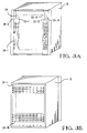
- FIG. 3A there are illustratively sixteen service termination unit circuit cards 22-1,...,22-16 which are installed vertically in the enclosure 10 from the rear thereof.
- the controller circuit card 26 which is comprised of two half-cards 26-1 and 26-2, is also installed vertically.
- FIG. 3B there are illustratively sixteen line termination unit circuit cards 20-1,...,20-16 which are installed horizontally in the enclosure 10 from the front thereof.
- Each of the line termination unit circuit cards 20-1,...,20-16 and the service termination unit circuit cards 22-1,...,22-16 has eight ports terminated by a respective media-specific connector on the visible edge of the circuit card away from the centerplane board 24 for connection to a respective user or service line.
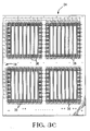
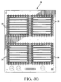
- FIGS. 3C and 3D illustrate opposite sides of the centerplane board 24.
- FIG. 3C shows the side of the centerplane board 24 on which the service termination unit circuit cards and the controller circuit cards are mounted
- FIG. 3D shows the side of the centerplane board 24 on which the line termination unit circuit cards are mounted.
- a pair of vertically oriented card edge connectors 36 for each of the service termination unit circuit cards and the controller circuit cards there is provided a pair of vertically oriented card edge connectors 36.
- FIG. 3D on the other side of the centerplane board 24 there is provided for each of the line termination unit circuit cards a pair of horizontally oriented card edge connectors 36.
- Each of the card edge connectors 36 has within it nine fields, each of which includes thirty six pins arranged in a square 6x6 matrix. The pins extend through the centerplane board 24 to a corresponding field in one of the card edge connectors 36 on the other side of the board 24, thereby interconnecting the connectors 36 on both sides of the board 24.
- each service termination unit circuit card's switch matrix portion are eight 4-wire bundles which are each connected to four pins of each of sixteen of the pin fields of the connector 36 associated with that service termination unit circuit card. Again, that accounts for thirty-two of the thirty-six pins in each of those sixteen pin fields, with the remaining four pins being reserved for the same power, ground and control signals.
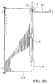
- FIG. 3E illustrates how the line termination unit circuit card 20-1 is connected to a pin field of the service termination unit circuit card 22-16, as well as to all corresponding pin fields of all the other fifteen service termination unit circuit cards.
- the pins 37 (a square 6x6 array) connect the card edge connectors 36 on the two sides of the centerplane board 24 at their intersections (i.e., at their common pin fields).
- the line termination unit circuit cards 20-1,...,20-16 take up the second through the seventeenth rows of the horizontal connectors 36 on their side of the centerplane board 24. The top and bottom rows are vacant.
- the service termination unit circuit cards 22-1,...,22-16 take up the third through the eighteenth columns of the vertical connectors 36 on their side of the board 24.
- any one of the service lines 16 can be connected to any one of the user lines 18.
- Each switch matrix portion on a service termination unit circuit card is an eight port by 128 port (32 by 512 lines) matrix of crosspoints.
- each of the 128 service lines can be connected to each of the 128 user ports.
- the bus 38 extends parallel to the leftmost column of the vertical connectors 36 and parallel to the upper row of the horizontal connectors 36 (not shown in FIG. 3C) on the other side of the board 24.
- the bus 38 is terminated at the pin fields in the second through seventeenth rows of the leftmost column for connection to the transceivers 30 on all of the line termination unit circuit cards 20-1,...,20-16; at the upper pin fields in the third through eighteenth columns for connection to the transceivers 32 on all of the service termination unit circuit cards 22-1,...,22-16; and at the upper pin field of the first column for connection to the transceiver 28 of the controller circuit card 26.
- the non-volatile RAM 108 may be an electrically erasable PROM or a "flash" PROM which saves its contents even when power is lost. Since it takes a relatively long time to write information into the non-volatile RAM 108, the RAM 106 is used to temporarily store the map until such time as it is written into the non-volatile RAM 108.
- the line termination unit circuit card 20 illustrated in FIG. 5 includes the transceiver 30 coupled to the bus lines 38 on the centerplane board 24.
- the transceiver 30 is a Neuron® chip manufactured by Echelon Corp.
- the function of the line termination unit circuit card 20 is to provide interfaces between the user lines 18 and the switch matrices on the service termination unit circuit cards 22-1,...,22-16 mounted on the other side of the centerplane board 24. This interfacing takes place via user line circuit paths which include the cable drivers (amplifiers) 110.
- the cable drivers 110 are selectively controllable to pass signals either from individual ones of the service lines 16 to individual ones of the user lines 18 or in the reverse direction from individual ones of the user lines 18 to individual ones of the service lines 16, as determined by the settings of respective ones of the control relays 112.
- the control relays 112 are controlled by the relay drivers 114 which are operated on the basis of instructions received via the transceiver 30 from the microprocessor 102 of the controller 26 over the bus lines 38 on the centerplane board 24. Initially, all the cable drivers 110 are set to pass signals in the direction from the user lines 18 to the service lines 16, with the cable drivers being bypassed. This is for safety reasons so that upon system start-up dangerously high amplified signals are not inadvertently transmitted to the user lines 18, where they could damage sensitive equipment.
- FIG. 6 illustrates the circuitry 22 on one of the service termination unit circuit cards 22-1,...,22-16.
- This circuitry includes a microprocessor 116 having associated therewith three types of memory.
- These memories function similarly to the memories 104, 106 and 108, respectively, associated with the microprocessor 102 of the controller 26, but are specifically for the particular one of the service termination unit circuit cards 22-1,...,22-16 with which they are associated.
- the microprocessor 116 is coupled to the transceiver 32, which is illustratively a Neuron® chip manufactured by Echelon Corp.
- the transceiver 32 is coupled to the bus lines 38 on the centerplane board 24 and is utilized for communications between the microprocessor 116 and the microprocessor 102 on the controller circuit card 26. Instructions received by the microprocessor 116 via the transceiver 32 over the bus 38 from the microprocessor 102 are utilized to control the relay drivers 124 and the switch matrix 126.
- the relay drivers 124 set the control relays 128 so that the cable drivers 130 interposed between the service lines 16 and the switch matrix 126 are "pointing" in the proper directions. At system start-up, for safety reasons the cable drivers 130 are initially bypassed.
- the switch matrix 126 is connected to all of the line termination unit circuit cards 20-1,...,20-16 mounted on the other side of the centerplane board 24, as previously described, so that any one of the service lines 16 entering that particular service termination unit circuit card may be connected to any one of the user lines 18.
- the microprocessor 116 controls the switch matrix 126 to make an appropriate physical electrical connection therethrough between a specified one of the service lines 16 entering that card and a specified one of the user lines 18 entering any one of the line termination unit circuit cards 20-1,...,20-16 on the other side of the centerplane board 24.
- each of the Ethernet circuits 202, 204, 206, 208 includes two balanced line-pairs each individually adapted for directional signal transmission, the number of crosspoint switches shown in Figure 7 may be reduced by the arrangement shown in Figure 8.
- the balanced line-pair 218 of the circuit 202 on which signals are transmitted into the matrix 220 is to be connected to the balanced line-pair 222 of the circuit 206, on which signals are transmitted out of the matrix 220.
- the balanced line-pair 224 of the circuit 202, on which signals are transmitted out of the matrix 220 is connected to the balanced line-pair 226 of the circuit 206, on which signals are transmitted into the matrix 220.
- pairs of wires are connected to pairs of wires through the matrix 220, only four crosspoint switches are necessary for making the connection between the four-wire Ethernet circuit 202 and the four-wire Ethernet circuit 206, as shown in Figure 8.
- the row and column lines are separated into first and second pluralities in order to account for the directivity of signal transmission of the balanced line-pairs.
- a first plurality of individual lines 240 are each connected to a respective one of either the first plurality of row lines 230 or the first plurality of column lines 234.
- a second plurality of individual lines 242 are each connected to a respective one of either the second plurality of row lines 232 or the second plurality of column lines 236.
- each of the four-wire Ethernet circuits is made up of two balanced line-pairs, the signals on a balanced line-pair which are entering the switching matrix 228 must be converted to signals on one of the individual lines 240 and, conversely, the signals on the individual lines 242 which are leaving the switching matrix 228 must be converted to differential signals on a balanced line-pair. Accordingly, such conversion is effected by providing a first plurality of transformers 244 and a second plurality of transformers 246.
- the first plurality of transformers 244 converts the differential signals on the balanced line-pairs to signals on respective ones of the individual lines 240
- the second plurality of transformers 246 converts the signals on the individual lines 242 to differential signals on respective balanced line-pairs.
- each of the first plurality of transformers has a first winding 248 and a second winding 250.
- the first winding 248 is connected to a respective balanced line-pair, illustratively the line-pair 218.
- a first end of the second winding 250 is connected to a respective individual line 240 and the second end of the second winding 250 is connected to a reference potential, illustratively ground.
- each of the second plurality of transformers 246 includes a first winding 252 and a second winding 254.
- the first winding 252 of the transformer 246 is connected to a respective balanced line-pair, illustratively the line-pair 224.
- a first end of the second winding 254 is connected to a respective one of the individual lines 242 and the other end of the second winding 254 is connected to a reference potential, illustratively ground.
- the crosspoint switches 238 are capacitive in nature, there is provided in series with each of the individual lines 240 an amplification means 256 for driving all of the crosspoint switches 238 associated with that line 240. Similarly, for the signals leaving the crosspoint switches 238, there is provided an amplification means 258 which is serially connected in each of the individual lines 242 for driving the line-pair connected to the respective transformer 246.
- the amplifiers and transformers associated with the user lines are mounted on the line termination unit circuit cards.
- Figure 10 shows an arrangement according to a second embodiment of the present invention where, as with Figure 9, the number of crosspoint switches is reduced by a factor of two from that shown in Figure 8.
- the embodiment of Figure 10 differs from that of Figure 9 in that signal conversion is effected by means of differential input operational amplifiers and differential output operational amplifiers, instead of by transformers.
- Each of the first plurality of amplifiers 270 is a differential input operational amplifier having a pair of differential inputs 274 and 276 and a single ended output 278.
- Each of the second plurality of amplifiers 272 has a single ended input 280 and a pair of differential outputs 282 and 284.
- Each of the first plurality of amplifiers 270 has its differential inputs 274, 276 connected to a respective balanced line-pair carrying signals entering the switching matrix 228 (e.g., the balanced line-pairs 218 and 226) and has its single ended output 278 connected to a respective one of the individual lines 240.
- each of the second plurality of amplifiers 272 has its differential outputs 282, 284 connected to a respective one of the balanced line-pairs carrying signals exiting the switching matrix 228 (e.g., the balanced line-pairs 224 and 222) and has its single ended input 280 connected to a respective one of the individual lines 242.
- the first plurality of amplifiers 270 provide sufficient amplification for driving the crosspoint switches 238, and the second plurality of amplifiers 272 provide sufficient amplification for driving their associated balanced line-pairs.
- the embodiment illustrated in Figure 10 does not require the additional amplification means required by the embodiment illustrated in Figure 9.
- the amplifiers of the embodiment shown in Figure 10 associated with the user lines are preferably mounted on the line termination unit circuit cards.
- the present invention recognizes that, when dealing with balanced line-pairs, such pairs are always connected to other such pairs. Further, the differential signal on each of the balanced line-pairs is converted to a single-ended signal on an individual line, which is then switched by a switch matrix and converted back to a differential signal on a balanced line-pair, with suitable amplifiers/drivers for driving the crosspoint switches and the line-pairs exiting the switch matrix.
- suitable amplifiers/drivers for each four-wire circuit which comprises two balanced line-pairs, only two crosspoint switches are required to make a connection to a similar such four-wire circuit.
Landscapes
- Engineering & Computer Science (AREA)
- Computer Networks & Wireless Communication (AREA)
- Use Of Switch Circuits For Exchanges And Methods Of Control Of Multiplex Exchanges (AREA)
- Data Exchanges In Wide-Area Networks (AREA)
- Small-Scale Networks (AREA)
- Structure Of Telephone Exchanges (AREA)
Applications Claiming Priority (2)
| Application Number | Priority Date | Filing Date | Title |
|---|---|---|---|
| US17343393A | 1993-12-23 | 1993-12-23 | |
| US173433 | 1993-12-23 |
Publications (2)
| Publication Number | Publication Date |
|---|---|
| EP0660622A2 true EP0660622A2 (fr) | 1995-06-28 |
| EP0660622A3 EP0660622A3 (fr) | 1997-05-14 |
Family
ID=22631997
Family Applications (1)
| Application Number | Title | Priority Date | Filing Date |
|---|---|---|---|
| EP94308319A Withdrawn EP0660622A3 (fr) | 1993-12-23 | 1994-11-10 | Communication de paires de lignes symmétriques dans un réseau de gestion de câbles avec un nombre réduit de commutateurs de croisement. |
Country Status (7)
| Country | Link |
|---|---|
| EP (1) | EP0660622A3 (fr) |
| JP (1) | JPH07240948A (fr) |
| CN (1) | CN1112319A (fr) |
| CA (1) | CA2135264A1 (fr) |
| CZ (1) | CZ314694A3 (fr) |
| HU (1) | HU214431B (fr) |
| PL (1) | PL306248A1 (fr) |
Cited By (1)
| Publication number | Priority date | Publication date | Assignee | Title |
|---|---|---|---|---|
| GB2345216A (en) * | 1998-12-22 | 2000-06-28 | Maddox Broadcast Ltd | Signal handling apparatus |
Family Cites Families (6)
| Publication number | Priority date | Publication date | Assignee | Title |
|---|---|---|---|---|
| US3885117A (en) * | 1974-04-03 | 1975-05-20 | Kenneth Owen | Balanced line switch system |
| JPS5917595B2 (ja) * | 1979-11-29 | 1984-04-21 | 岩崎通信機株式会社 | 通話路スイツチ回路網 |
| NL8000529A (nl) * | 1980-01-29 | 1981-08-17 | Philips Nv | Schakelmatrix. |
| JPH01216630A (ja) * | 1988-02-24 | 1989-08-30 | Matsushita Electric Works Ltd | ノイズ除去回路 |
| JP2741384B2 (ja) * | 1988-06-27 | 1998-04-15 | 日通工株式会社 | 平衡‐不平衡変換回路 |
| JPH04142824A (ja) * | 1990-10-03 | 1992-05-15 | Nec Corp | データ伝送方式 |
-
1994
- 1994-11-07 CA CA 2135264 patent/CA2135264A1/fr not_active Abandoned
- 1994-11-10 EP EP94308319A patent/EP0660622A3/fr not_active Withdrawn
- 1994-11-15 HU HU9403274A patent/HU214431B/hu not_active IP Right Cessation
- 1994-12-12 PL PL30624894A patent/PL306248A1/xx unknown
- 1994-12-14 CZ CZ943146A patent/CZ314694A3/cs unknown
- 1994-12-22 CN CN 94119173 patent/CN1112319A/zh active Pending
- 1994-12-22 JP JP33651994A patent/JPH07240948A/ja active Pending
Cited By (2)
| Publication number | Priority date | Publication date | Assignee | Title |
|---|---|---|---|---|
| GB2345216A (en) * | 1998-12-22 | 2000-06-28 | Maddox Broadcast Ltd | Signal handling apparatus |
| GB2345216B (en) * | 1998-12-22 | 2002-12-31 | Maddox Broadcast Ltd | Signal handling apparatus |
Also Published As
| Publication number | Publication date |
|---|---|
| CN1112319A (zh) | 1995-11-22 |
| PL306248A1 (en) | 1995-06-26 |
| CZ314694A3 (en) | 1995-07-12 |
| JPH07240948A (ja) | 1995-09-12 |
| EP0660622A3 (fr) | 1997-05-14 |
| HUT69826A (en) | 1995-09-28 |
| HU214431B (hu) | 1998-03-30 |
| CA2135264A1 (fr) | 1995-06-24 |
| HU9403274D0 (en) | 1995-01-30 |
Similar Documents
| Publication | Publication Date | Title |
|---|---|---|
| US5541586A (en) | Visual outlet identification in a cable management system | |
| US5432505A (en) | Cable management system with automatic mapping | |
| US5523747A (en) | Asset management in a cable management system | |
| US5515037A (en) | Wire selection in a cable management system | |
| US3978291A (en) | Automated main distributing frame system | |
| US4670626A (en) | Cross connect frame for digital signals | |
| EP0624043A1 (fr) | Système de gestion de câbles | |
| WO2007103462A1 (fr) | Dispositif de distribution de télécommunication equipé d'une carte à circuits multiples | |
| CA2135264A1 (fr) | Commutation de paires de lignes symetriques dans un systeme de gestion de cables a nombre restreint de commutateurs de croisement | |
| WO1995027379A1 (fr) | Systeme de gestion de cables par controle de ligne a distance | |
| US7746983B2 (en) | Distributor with a test access | |
| EP0654674A2 (fr) | Système de gestion de câbles avec test des lignes de service et d'abonné | |
| EP0657741A2 (fr) | Système de gestion de câbles avec test à distance des lignes par l'intermédiaire d'un commutateur | |
| US4661971A (en) | Digital signal cross-connection system | |
| US20070211740A1 (en) | Telecommunications distribution system with line sharing | |
| US6535602B1 (en) | Telecommunications wiring device | |
| JP2823023B2 (ja) | リンク配線用マトリクスプリント板におけるコネクタ接続方法 | |
| US2485986A (en) | Automatic telephone system | |
| KR940027614A (ko) | 케이블 관리 시스템 | |
| GB2132445A (en) | Main distribution frame arrangement | |
| CZ280094A3 (en) | Device for controlling cable network with testing order-wire and subscriber's circuits | |
| US20080291898A1 (en) | Provision of Telecommunication Services | |
| CZ210795A3 (en) | Apparatus for controlling a cable network with testing an order-wire circuit and subscriber's line user- | |
| JPH0993622A (ja) | 自動主配線盤装置の大規模リンク構造 | |
| JPH0993621A (ja) | 自動主配線盤装置の3段リンク構造 |
Legal Events
| Date | Code | Title | Description |
|---|---|---|---|
| PUAI | Public reference made under article 153(3) epc to a published international application that has entered the european phase |
Free format text: ORIGINAL CODE: 0009012 |
|
| AK | Designated contracting states |
Kind code of ref document: A2 Designated state(s): DE FR GB IT NL |
|
| PUAL | Search report despatched |
Free format text: ORIGINAL CODE: 0009013 |
|
| AK | Designated contracting states |
Kind code of ref document: A3 Designated state(s): DE FR GB IT NL |
|
| STAA | Information on the status of an ep patent application or granted ep patent |
Free format text: STATUS: THE APPLICATION IS DEEMED TO BE WITHDRAWN |
|
| 18D | Application deemed to be withdrawn |
Effective date: 19971115 |