EP0660631A2 - Système de l'allocation d'un canal pour des systèmes de communication et appareil pour la mise en oeuvre - Google Patents
Système de l'allocation d'un canal pour des systèmes de communication et appareil pour la mise en oeuvre Download PDFInfo
- Publication number
- EP0660631A2 EP0660631A2 EP94120693A EP94120693A EP0660631A2 EP 0660631 A2 EP0660631 A2 EP 0660631A2 EP 94120693 A EP94120693 A EP 94120693A EP 94120693 A EP94120693 A EP 94120693A EP 0660631 A2 EP0660631 A2 EP 0660631A2
- Authority
- EP
- European Patent Office
- Prior art keywords
- base station
- wireless terminal
- channel
- sector
- communication
- Prior art date
- Legal status (The legal status is an assumption and is not a legal conclusion. Google has not performed a legal analysis and makes no representation as to the accuracy of the status listed.)
- Granted
Links
Images



Classifications
-
- H—ELECTRICITY
- H04—ELECTRIC COMMUNICATION TECHNIQUE
- H04W—WIRELESS COMMUNICATION NETWORKS
- H04W16/00—Network planning, e.g. coverage or traffic planning tools; Network deployment, e.g. resource partitioning or cells structures
- H04W16/02—Resource partitioning among network components, e.g. reuse partitioning
- H04W16/10—Dynamic resource partitioning
-
- H—ELECTRICITY
- H04—ELECTRIC COMMUNICATION TECHNIQUE
- H04W—WIRELESS COMMUNICATION NETWORKS
- H04W16/00—Network planning, e.g. coverage or traffic planning tools; Network deployment, e.g. resource partitioning or cells structures
- H04W16/02—Resource partitioning among network components, e.g. reuse partitioning
- H04W16/12—Fixed resource partitioning
-
- H—ELECTRICITY
- H04—ELECTRIC COMMUNICATION TECHNIQUE
- H04W—WIRELESS COMMUNICATION NETWORKS
- H04W16/00—Network planning, e.g. coverage or traffic planning tools; Network deployment, e.g. resource partitioning or cells structures
- H04W16/24—Cell structures
-
- H—ELECTRICITY
- H04—ELECTRIC COMMUNICATION TECHNIQUE
- H04W—WIRELESS COMMUNICATION NETWORKS
- H04W24/00—Supervisory, monitoring or testing arrangements
- H04W24/10—Scheduling measurement reports ; Arrangements for measurement reports
-
- H—ELECTRICITY
- H04—ELECTRIC COMMUNICATION TECHNIQUE
- H04W—WIRELESS COMMUNICATION NETWORKS
- H04W72/00—Local resource management
- H04W72/20—Control channels or signalling for resource management
- H04W72/21—Control channels or signalling for resource management in the uplink direction of a wireless link, i.e. towards the network
-
- H—ELECTRICITY
- H04—ELECTRIC COMMUNICATION TECHNIQUE
- H04W—WIRELESS COMMUNICATION NETWORKS
- H04W72/00—Local resource management
- H04W72/50—Allocation or scheduling criteria for wireless resources
- H04W72/54—Allocation or scheduling criteria for wireless resources based on quality criteria
- H04W72/541—Allocation or scheduling criteria for wireless resources based on quality criteria using the level of interference
-
- H—ELECTRICITY
- H04—ELECTRIC COMMUNICATION TECHNIQUE
- H04W—WIRELESS COMMUNICATION NETWORKS
- H04W72/00—Local resource management
- H04W72/50—Allocation or scheduling criteria for wireless resources
- H04W72/54—Allocation or scheduling criteria for wireless resources based on quality criteria
- H04W72/542—Allocation or scheduling criteria for wireless resources based on quality criteria using measured or perceived quality
Definitions
- the present invention relates to channel allocation systems for cellular mobile communications systems covering several zones by using base stations for each zone, in particular, channel allocation systems for mobile communications systems that divide the above-mentioned zones into fan-shaped cell (sector cells) for each directional gain of sector antennas (antennas having different horizontal plane directivity), by contacting these sector antennas to each of the above-mentioned base stations.
- channel allocation systems for mobile communications systems that divide the above-mentioned zones into fan-shaped cell (sector cells) for each directional gain of sector antennas (antennas having different horizontal plane directivity), by contacting these sector antennas to each of the above-mentioned base stations.
- Cellular mobile communications system such as car telephone systems repeatedly use the same wireless channels (channels) between zones that do not interfere with one another.
- Configuration of the above-mentioned zones in these mobile communications systems can be either omni zone configuration or sector zone configuration.
- omni zone configuration one antenna with no horizontal plane directivity (omni antenna) is installed at each base station to cover one zone centered around the base station supported by this omni antenna.
- sector zone configuration one base station is equipped with a number of sector antennas having directivity within fan-shaped horizontal planes and each of the above-mentioned sector antennas covers a fan-shaped area (sector cell) corresponding to directional gain of that antenna.
- the above-mentioned mobile communications system also includes a number of fixed or mobile wireless terminals in the above-mentioned zones. These wireless terminals communicate with different wireless terminals or public communications nets via wireless channels (communication channels) between the wireless terminals and base stations of the zones to which they belong.
- Allocation systems for communications channels of the above-mentioned mobile communications systems are classified as fixed channel allocation systems and dynamic channel allocation systems.
- Fixed channel allocation systems allocate channels for communications beforehand in a fixed way for each zone, taking into account mutual interference conditions between zones.
- the dynamic channel allocation system does not allocate channels in a fixed manner to each zone.
- the base station sequentially selects a channel from among all channels for each communication request and certain allocation preconditions (communication quality) are satisfied at a channel, for example, the ratio between received power (desired wave power) of the signal from the other end of the communication link (one wireless terminal) and interference wave power (hereafter, this ratio is abbreviated as "CIR") exceeds certain threshold values for both uplink (transmission from wireless terminal, with base station the reception circuit) and downlink (transmission from base station, with the wireless terminal the reception circuit), the channel that satisfies those conditions is allocated as the communication channel.
- This dynamic channel allocation system makes effective use of channels through the collective use of all channels by all base stations.
- the same channel can be re-used as long as the CIR threshold value is satisfied, the same channels can be re-used within shorter distances than with the fixed channel allocation system, making even more efficient use of channels.
- the dynamic channel allocation system higher frequency (channel) usage efficiency than with the fixed channel allocation system is obtainable.
- One conceivable way of obtaining high-frequency (channel) usage efficiency is to use a combination of sector cell zone configuration and dynamic channel allocation.
- a sector cell zone configured dynamic channel allocation system there is an allocation system that prioritizes the same channels for sector cells in the same direction (Japanese Patent Laid-Open No.081101 (1993)).
- Japanese Patent Laid-Open No.081101 (1993) Japanese Patent Laid-Open No.081101 (1993)
- the mobile communications system in Fig.5 uses a sector zone configuration.
- a base station (BS) 11 is established in the first zone and base stations 12 and 13 are established in the second and third zones, respectively.
- This mobile communications system has many other zones as well, but, as explanations of these zones are unnecessary, they are not included in the figures.
- a sector antennas 31 (31a, 31b, 31c, 31d, 31e and 31f), whose horizontal plane directivity has a 60° half-value width angle (the angular width that encompasses the point where directional gain is just 3 dB smaller than directional gain in the central direction, where direction of maximum emission intensity is the center) are established.
- the sector antennas 31a, 31b, 31c, 31d, 31e and 31f are positioned in correspondence with the above-mentioned horizontal plane directivity to cover 6 equal sector cells 41 (41a, 41b, 41c, 41d, 41e and 41f), respectively around the base station 11.
- the 6 sector antennas each of antennas 32 and 33 of the base stations 12 and 13 cover sector cells 42 and 43, respectively.
- a wireless terminal 21 is located in sector cell 41f
- wireless terminal 22 is located in the sector cell 42f
- the wireless terminal 23 is located in the sector cell 43a.
- the base station 12 is currently using channel CH2 to communicate with the wireless terminal 22
- the base station 13 is using channel CH3 to communicate with the wireless terminal 23 and the base station 11 allocates a new channel to the wireless terminal 21.
- channel CH3 is the channel in which difference between the arrival direction of desired wave and that of interference wave in the wireless terminal 21 downlink becomes smaller, but in the wireless terminal 21 the allocated channel is channel CH2, for which the difference between the arrival directions of desired wave and interference wave becomes greater.
- the prior channel allocation system that the sector cells of the same direction are preferentially allocated involves a problem of not adequately obtaining the above-mentioned benefit in downlinks from the correlations of locational variation of desired waves to locational variation of interference waves.
- the object of the present invention is achieved by a channel allocation system for communication systems, by which a proper communication channel between a wireless terminal and a base station is allocated when a communication request has arisen between said wireless terminal and said base station to which said wireless terminal belongs, where the channel allocation system for communication systems comprising: a step of measuring a received level of a desired wave from the wireless terminal in each sector cell of the base station and calculating an arrival direction of the desired wave, in the base station; a step of measuring a received level of an interference wave from a channel that is used by other base stations and other wireless terminals in each sector cell of the base station and calculating an arrival direction of the interference wave, in the base station; and a step of allocating a communication channel of which angle difference in a horizontal plane between the arrival direction of the desired wave and the arrival direction of the interference wave is closest to 180° for communication between the wireless terminal and the base station.
- the present invention makes possible reduction of the probability of reduced quality during communication in mobile communications systems using the sector zone configuration and dynamic allocation system by prioritized allocation of channels for which the differences in angles of arrival directions of desired and interference waves in downlinks are small, thereby increasing correlations of reception levels of desired waves and interference waves on downlinks to locational variation as wireless terminals are moved.
- Fig.1 is a conceptual system diagram of the first embodiment of the present invention.
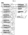
- Fig.2 is a block diagram explaining the first embodiment.
- Fig.3 is a block diagram explaining the second embodiment.
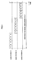
- Fig.4 is a figure for explaining operations of identification signal call in the second embodiment.
- Fig.5 is a conceptual system diagram of a prior mobile communications system.
- Fig.1 is a conceptual system diagram of an embodiment of the present invention. The first embodiment is configured by the system shown in Fig.1.
- This cellular mobile communications system provides 3 zones, held respectively by base stations (BS) 11, 12 and 13.
- the 6 sector antennas 31 (31a, 31b, 31c, 31d, 31e and 31f), each having a horizontal plane directivity whose half-value width angle is 60° are connected to the input terminals of the reception section of the base station 11.
- These sector antennas 31a, 31b, 31c, 31d, 31e and 31f cover sector cells 41 (41a, 41b, 41c, 41d, 41e and 41f), respectively, which divide the area around base station 11 into 6 equal parts corresponding to above-mentioned horizontal plane directivity.
- the input terminals of the reception sections of base stations 12 and 13 each are connected to 6 sector antennas 32 (32a, 32b, 32c, 32d 32e and 32f) and 33 (33a, 33b, 33c, 33d, 33e and 33f), and these sector antennas 32a, 32b, 32c, 32d, 32e, 32f, 33a, 33b, 33c, 33d, 33e and 33f each cover sector cells 42 (42a, 42b, 42c, 42d, 42e and 42f) and 43 (43a, 43b, 43c, 43d, 43e and 43f), which divide the area around the base stations 11 and 12 into 6 equal parts, respectively.
- base stations 11, 12 and 13 are located as shown in the figure.
- respective sector cells noted by using the same lower case alphabetic letters are arranged in the same direction centering around corresponding base stations.
- respective sector antennas noted by using the same lower case alphabetic letters are provided in the same direction centering around corresponding base stations.
- the directivity direction of sector antennas 31a, 32a and 33a is given as 0°, of sector antennas 31b, 32b and 33b, 60°, of sector antennas 31c, 32c and 33c, 120°, of sector antennas 31d, 32d and 33d, 180°, of sector antennas 31e, 32e and 33e, 240° and of sector antennas 31f, 32f and 33f, 300°.
- the wireless terminal 21 is located in the sector cell 41f
- the wireless terminal 22 is located in the sector cell 42f
- the wireless terminal 23 is located in the sector cell 43a
- the wireless terminal 24 is located in the sector cell 43f.
- this mobile communications system has one control channel used for controlling connection and three communication channels CH1 to CH3.
- Fig.2 is a block diagram showing an internal configuration of the base station 11.
- explanation for the other base stations such as 11 or 12 is omitted, because the configurations of the base stations 12 and 13 are the same as that of the base station 11.
- Numbers 1a to 1f are desired wave level measurement sections corresponding to each sector antenna. They measures a received level of a desired wave from a wireless terminal.
- Numbers 2a to 2f are interference wave level measurement sections corresponding to each sector antenna. They measures a level of an interference wave of a channel used by other base stations and other wireless terminals.
- Number 3 is a desired wave arrival direction estimator for receiving received levels of the desired wave level measurement sections 1a to 1f and calculating a maximum received level. Then it outputs a direction of a sector antenna corresponding to the maximum received level as an arrival direction of a desired wave.
- Number 4 is an interference wave arrival direction estimator for receiving received levels of the desired wave level measurement sections 1a to 1f and calculating a maximum received level. Then it outputs a direction of a sector antenna corresponding to the maximum received level as an arrival direction of an interference wave.
- Number 5 is a channel selection sequence deciding section. It receives an arrival direction of a desired wave from the desired wave arrival direction estimator 3 and an arrival direction of an interference wave from the interference wave arrival direction estimator 4, and decides communication channel selection sequence in order so as a channel of which angle difference between the arrival direction of an interference wave and the arrival direction of a desired wave is closest to 180° is first.
- Number 6 is a channel allocating section. It checks communication quality in the order decided by the channel selection sequence deciding section 5, and allocates the best channel for communication with a wireless terminal.
- the base station 12 is using channel CH2 to communicate with wireless terminal 22.
- the base station 13 is using channel CH3 to communicate with the wireless terminal 23 and using channel CH1 to communicate with the wireless terminal 24.
- the wireless terminal 21 uses the control channel to transmit the signal.
- the base station 11 uses all sector antennas 31 connected to it to measure reception level (desired wave level) of the signal from wireless terminal 21.
- the base station 11 in turn, also measures interference wave levels of channels CH1, CH2 and CH3.
- desired wave levels received by the desired wave level measurement sections 1a to 1f of the base station 11 from sector antennas 31a, 31b, 31c, 31d, 31e and 31f are given as Da, Db, Dc, Dd, De and Df.
- the interference wave levels of CH1 received by the interference wave level measurement sections 2a to 2f of the base station 11 from sector antennas 31a, 31b, 31c, 31d, 31e and 31f are given as U1a, U1b, U1c, U1d, U1e and U1f, respectively
- the interference wave levels of channel CH2 are given as U2a, U2b, U2c, U2d, U2e and U2f
- the interference wave levels of channel CH3 are given as U3a, U3b, U3c, U3d, U3e and U3f, respectively.
- Df has the maximum value of the desired wave levels from the wireless terminal 21 among Da, Db, Dc, Dd, De and Df, which are measured by each sector antenna. It is determined by the desired wave arrival direction estimator 3 that arrival direction of the desired waves is 300°, the directivity direction of sector antenna 31f.
- interference wave level U1c is maximum among interference wave levels U1a, U1b, U1c, U1d, U1e and U1f from the wireless terminal 24 measured by each sector antenna. It is, therefore, determined that arrival direction of channel CH1 interference wave is 120°, the directivity direction of sector antenna 31c.
- interference wave level U2d is maximum among interference wave levels U2a, U2b, U2c, U2d, U2e and U2f from the wireless terminal 24 measured by each sector antenna. It is, therefore, determined that arrival direction of channel CH2 interference wave is 180°, the directivity direction of sector antenna 31d.
- interference wave level U3c is maximum among interference wave levels U3a, U3b, U3c, U3d, U3e and U3f from the wireless terminal 23 measured by each sector antenna. It is, therefore, determined that arrival direction of channel CH3 interference wave is 120°, the directivity direction of sector antenna 31c.
- the identifier transmitter 5 of the base station 11 determines channel selection sequence, using desired wave arrival directions and arrival directions of interference waves to channels CH1, Ch2 and CH3.
- the arrival directions of interference waves to channels CH1, CH2 and CH3 are 120°, 180° and 120°, respectively. Since the arrival direction of the desired wave is 300°, the differences between the angles of the arrival directions of the interference waves and the desired waves are 180°, 120° and 180°, respectively.
- channels are selected starting with those for which the difference between angles of arrival direction of interference waves and desired waves are closest to 180°.
- the sequence of selection is "CH1, CH3, CH2" or "CH3, CH1, CH2".
- the sequence can be decided optionally.
- the channel selection sequence is "CH1, CH3, CH2".
- this base station 11 uses the sector antenna 31f to communicate with the wireless terminal 21.
- channel CH1 is selected, and channel interference ratio (CIR) for desired waves to this channel and the electric power of interference waves, that is, the ratio of desired wave level Df to interference wave level U1f at the sector antenna 31f, is calculated. If this exceeds a certain fixed value, the base station 11 indicates a quality evaluation on the usability (or unusability) of the channel CH1 with the wireless terminal 21.
- the wireless terminal 21 measures the level of the interference waves to channel CH1 and calculates the ratio of desired wave level or reception level of the signal from the base station 11 to interference wave level.
- the base station 13 determines whether or not it exceeds a certain fixed value.
- the base station 13 is using channel CH1 via the sector antenna 33f, whose directivity direction includes the location of wireless terminal 21, there is a high level of interference waves to the wireless terminal 21, so channel CH1 cannot be allocated.
- the wireless terminal 21 notifies the base station 11 that channel CH1 cannot be used.
- the base station 11 selects channel CH3, and in the same way, calculates the ratio of desired wave level Df to interference wave level U3f on channel CH3. If this ratio exceeds the above-mentioned fixed value, it determines that the wireless terminal 21 cannot use channel CH3. At this time, because the base station 13 is using channel CH3 via the sector antenna 33a, whose directivity direction does not include the location of the wireless terminal 21, interference wave level to the wireless terminal 21 is small enough that channel CH3 can be used. Thus, the wireless terminal notifies the base station 11 that channel CH3 can be used, and, using channel CH3, begins communication with the base station 11.
- a identification signal announcing channel is further provided.
- an estimating method of an arrival direction of a desired wave when a communication request occurs between the base station 11 and the wireless terminal 21 in the movable communication system shown in Fig.1 is explained, because the configuration of the second embodiment is the same as that of the first embodiment other than the part of estimating an arrival direction of a desired wave.
- Fig.3 is a block diagram of the base station 11 of the second embodiment.
- Number 7 is a identification signal transmitter for transmitting a identification signal described later.
- Numbers 1 to 18 in Fig.4 are the slot numbers for the identification signal announcing channel.
- the base station 11 uses slots 1 to 6 of identification signal announcing channels to report a identification signal having each identifier for each sector antenna via the sector antennas 31a, 31b, 31c, 31d, 31e and 31f.
- the base station 12 uses slots 7-12 to report via the sector antennas 32a, 32b, 32c, 32d, 32e and 32f
- the base station 13 uses slots 13-18 to report via the sector antenna 33a, 33b, 33c, 33d, 33e and 33f their respective identification signals.
- the base station 11 again begins reporting, repeating the same cycle.
- the wireless terminal 21 receives identification signal announcing channels in order, measuring their respective levels.
- reception levels of the reported signal are referred to as S1a, S1b, S1c, S1d, S1e and S1f, respectively received by the reception section of the wireless terminal via the sector antennas 31a, 31b, 31c, 31d, 31e and 31f.
- reported signals are received via the sector antennas 32 and 33.
- reception level S1f becomes maximum of the received signals reported from the sector antenna 31f.
- the wireless terminal 21 reports identifier of the sector antenna 31f to the base station 11.
- the base station 11 estimates the arrival direction of the desired wave as 300°, because the directivity direction of sector antenna 31f is 300°. Following this, estimation of arrival direction of interference waves, determination of channel selection sequence, etc. are the same as in the first embodiment, their explanations are thus omitted.
- giving priority to channels for selection to those for which the differences between the angles of the arrival directions of the desired waves and the interference waves to the base station gives a small difference between the angles of the arrival direction of the desired waves and interference waves to the wireless terminal.
- the present invention is not limited to these embodiments only.
- accuracy of estimation of arrival directions is determined by the number of sector cells to base stations. Accuracy of estimation can be increased by establishing other antennas top be used in estimation of arrival direction. The use of antennas for estimation of arrival direction in this way does not hinder the use of the present invention.
Landscapes
- Engineering & Computer Science (AREA)
- Computer Networks & Wireless Communication (AREA)
- Signal Processing (AREA)
- Mobile Radio Communication Systems (AREA)
Applications Claiming Priority (3)
| Application Number | Priority Date | Filing Date | Title |
|---|---|---|---|
| JP330209/93 | 1993-12-27 | ||
| JP5330209A JP2661533B2 (ja) | 1993-12-27 | 1993-12-27 | 移動通信システムのチャネル割当方式 |
| JP33020993 | 1993-12-27 |
Publications (3)
| Publication Number | Publication Date |
|---|---|
| EP0660631A2 true EP0660631A2 (fr) | 1995-06-28 |
| EP0660631A3 EP0660631A3 (fr) | 1996-01-03 |
| EP0660631B1 EP0660631B1 (fr) | 2002-08-28 |
Family
ID=18230071
Family Applications (1)
| Application Number | Title | Priority Date | Filing Date |
|---|---|---|---|
| EP94120693A Expired - Lifetime EP0660631B1 (fr) | 1993-12-27 | 1994-12-27 | Procédé d'allocation de canal pour des systèmes de communication, et station de base et système de communication correspondants |
Country Status (5)
| Country | Link |
|---|---|
| US (1) | US5603082A (fr) |
| EP (1) | EP0660631B1 (fr) |
| JP (1) | JP2661533B2 (fr) |
| AU (1) | AU697509B2 (fr) |
| DE (1) | DE69431235T2 (fr) |
Cited By (3)
| Publication number | Priority date | Publication date | Assignee | Title |
|---|---|---|---|---|
| WO1997044982A3 (fr) * | 1996-05-20 | 1997-12-31 | Metawave Communications Corp | Systeme et procede pour la gestion du spectre de faisceaux dans un systeme cellulaire |
| US7489282B2 (en) | 2005-01-21 | 2009-02-10 | Rotani, Inc. | Method and apparatus for an antenna module |
| US9496930B2 (en) | 2006-02-28 | 2016-11-15 | Woodbury Wireless, LLC | Methods and apparatus for overlapping MIMO physical sectors |
Families Citing this family (52)
| Publication number | Priority date | Publication date | Assignee | Title |
|---|---|---|---|---|
| FR2736781B1 (fr) * | 1995-07-13 | 1997-09-26 | Sgs Thomson Microelectronics | Circuit de transmission de donnees binaires sur le reseau electrique utilisant plusieurs canaux de transmission |
| FR2736780B1 (fr) | 1995-07-13 | 1997-09-26 | Sgs Thomson Microelectronics | Circuit d'affectation d'un canal de transmission sur le reseau electrique |
| US5740537A (en) * | 1996-01-30 | 1998-04-14 | Telefonaktiebolaget L M Ericsson (Publ) | Method and circuitry for selectively permitting communication in a multi-user communication system |
| US5870676A (en) * | 1996-02-16 | 1999-02-09 | Hughes Electronics Corporation | Method and apparatus for monitoring killer channels in a cellular system |
| US5852633A (en) * | 1996-06-07 | 1998-12-22 | Motorola, Inc. | Method for allocating data in a data communication system |
| US6463295B1 (en) | 1996-10-11 | 2002-10-08 | Arraycomm, Inc. | Power control with signal quality estimation for smart antenna communication systems |
| US7035661B1 (en) | 1996-10-11 | 2006-04-25 | Arraycomm, Llc. | Power control with signal quality estimation for smart antenna communication systems |
| US6275543B1 (en) | 1996-10-11 | 2001-08-14 | Arraycomm, Inc. | Method for reference signal generation in the presence of frequency offsets in a communications station with spatial processing |
| US5886988A (en) * | 1996-10-23 | 1999-03-23 | Arraycomm, Inc. | Channel assignment and call admission control for spatial division multiple access communication systems |
| US5875180A (en) * | 1997-02-06 | 1999-02-23 | Globalstar L.P. | Satellite telephone interference avoidance system |
| US5867766A (en) * | 1997-04-25 | 1999-02-02 | Lucent Technologies Inc. | Technique for performing an automatic channel search and switch during talk-time in mobile transceivers |
| SE509776C2 (sv) * | 1997-07-04 | 1999-03-08 | Ericsson Telefon Ab L M | Anordning och förfarande vid antennlobsstyrning i radiokommunikationssystem |
| US6130882A (en) | 1997-09-25 | 2000-10-10 | Motorola, Inc. | Method and apparatus for configuring a communication system |
| US7299071B1 (en) | 1997-12-10 | 2007-11-20 | Arraycomm, Llc | Downlink broadcasting by sequential transmissions from a communication station having an antenna array |
| US6259746B1 (en) | 1998-01-14 | 2001-07-10 | Motorola Inc. | Method for allocating data and power in a discrete multi-tone communication system |
| US6275522B1 (en) | 1998-01-14 | 2001-08-14 | Motorola, Inc. | Method for allocating data and power in a discrete, multi-tone communication system |
| US5966054A (en) * | 1998-01-29 | 1999-10-12 | Motorola, Inc. | Method and apparatus for providing a clocking signal |
| US6094584A (en) * | 1998-03-26 | 2000-07-25 | Lucent Technologies, Inc. | Method for operating a wireless telecommunications system |
| US6615024B1 (en) | 1998-05-01 | 2003-09-02 | Arraycomm, Inc. | Method and apparatus for determining signatures for calibrating a communication station having an antenna array |
| US6542484B1 (en) * | 1998-05-15 | 2003-04-01 | Telefonaktiebolaget Lm Ericsson (Publ) | Code allocation for radiocommunication systems |
| JP3407671B2 (ja) | 1998-06-01 | 2003-05-19 | 三菱電機株式会社 | 無線通信システム及びその基地局 |
| US6452907B1 (en) | 1998-10-15 | 2002-09-17 | Motorola, Inc. | Method for monitoring unused bins in a discrete multi-toned communication system |
| JP3229864B2 (ja) * | 1999-03-24 | 2001-11-19 | 三洋電機株式会社 | 伝送チャネルの割当方法およびそれを用いた無線装置 |
| US6418327B1 (en) * | 1999-04-06 | 2002-07-09 | Spike Broadband Systems, Inc. | Methods and determining an optimum sector distribution within a coverage area of a wireless communication system |
| JP2000308124A (ja) | 1999-04-26 | 2000-11-02 | Mitsubishi Electric Corp | 制御チャネル配置方法 |
| US6600914B2 (en) | 1999-05-24 | 2003-07-29 | Arraycomm, Inc. | System and method for emergency call channel allocation |
| US6141567A (en) | 1999-06-07 | 2000-10-31 | Arraycomm, Inc. | Apparatus and method for beamforming in a changing-interference environment |
| US7139592B2 (en) * | 1999-06-21 | 2006-11-21 | Arraycomm Llc | Null deepening for an adaptive antenna based communication station |
| EP1079578A3 (fr) * | 1999-08-23 | 2001-11-07 | Motorola, Inc. | Allocation de données dans des systèmes multiporteuses |
| WO2001018996A1 (fr) * | 1999-09-08 | 2001-03-15 | Motorola Inc. | Procede de transmission par paquets |
| US20050009528A1 (en) * | 1999-10-21 | 2005-01-13 | Mikio Iwamura | Channel identifier assigning method and mobile communications system |
| JP3764612B2 (ja) * | 1999-10-21 | 2006-04-12 | 株式会社エヌ・ティ・ティ・ドコモ | チャネル識別子の割り当て方法および移動通信システム |
| US6985466B1 (en) | 1999-11-09 | 2006-01-10 | Arraycomm, Inc. | Downlink signal processing in CDMA systems utilizing arrays of antennae |
| US6640104B1 (en) * | 1999-12-28 | 2003-10-28 | Lucent Technologies Inc. | Dynamic channel assignment for intelligent antennas |
| JP2001196975A (ja) | 2000-01-17 | 2001-07-19 | Nec Corp | Cdma方式無線基地局用の同期捕捉回路 |
| US6982968B1 (en) | 2000-09-29 | 2006-01-03 | Arraycomm, Inc. | Non-directional transmitting from a wireless data base station having a smart antenna system |
| US7062294B1 (en) | 2000-09-29 | 2006-06-13 | Arraycomm, Llc. | Downlink transmission in a wireless data communication system having a base station with a smart antenna system |
| US6795409B1 (en) | 2000-09-29 | 2004-09-21 | Arraycomm, Inc. | Cooperative polling in a wireless data communication system having smart antenna processing |
| JP3543764B2 (ja) | 2000-12-21 | 2004-07-21 | 日本電気株式会社 | 無線通信システム及び干渉波監視方法 |
| TWI493914B (zh) | 2002-05-13 | 2015-07-21 | Interdigital Tech Corp | 使用波束之有槽分碼多重存取系統中分配資源於使用者 |
| US7046655B2 (en) * | 2002-08-15 | 2006-05-16 | Interdigital Technology Corporation | Wireless communication method and system for minimizing interference by determining mobile station zone locations and potential conflicts between cell zones |
| US7302278B2 (en) * | 2003-07-03 | 2007-11-27 | Rotani, Inc. | Method and apparatus for high throughput multiple radio sectorized wireless cell |
| US20060067269A1 (en) * | 2004-09-27 | 2006-03-30 | Enrico Jugl | Method of scheduling users in wireless communication networks |
| KR101239796B1 (ko) * | 2005-12-14 | 2013-03-06 | 삼성전자주식회사 | 공간 분할 다중 접속 통신 장치 및 방법 |
| GB2440982A (en) * | 2006-08-18 | 2008-02-20 | Fujitsu Ltd | Wireless multi-hop communication system |
| WO2009094264A2 (fr) * | 2008-01-24 | 2009-07-30 | Firetide, Inc. | Attribution de canal pour des réseaux d'accès sans fil |
| EP2129178A1 (fr) * | 2008-05-06 | 2009-12-02 | Alcatel Lucent | Procédé pour affecter des subcanaux de fréquences sur une interface radio d'un système de communications sans fil et module d'affectation de ressources radio correspondante |
| US9917669B2 (en) * | 2013-08-26 | 2018-03-13 | National Chiao Tung University | Access point and communication system for resource allocation |
| GB2558587B (en) | 2017-01-08 | 2020-12-09 | Ocado Innovation Ltd | Wireless communication system with detectors for extraneous received signals |
| FR3105672A1 (fr) | 2019-12-20 | 2021-06-25 | Orange | Procédé d’allocation de fréquences d’émission de signaux radio entre une ou plusieurs entités de communication, permettant une réduction des interférences entre ces entités de communication utilisant 5 le même canal en fréquence |
| FR3105671A1 (fr) | 2019-12-20 | 2021-06-25 | Orange | Procédé d’allocation de fréquences d’émission de signaux radio entre une ou plusieurs entités de communication, permettant une réduction des interférences entre ces entités de communication utilisant le même canal en fréquence |
| CN114499616B (zh) * | 2022-01-29 | 2024-10-15 | 重庆邮电大学 | 一种缓解蜂窝网络干扰的资源分配方法 |
Family Cites Families (7)
| Publication number | Priority date | Publication date | Assignee | Title |
|---|---|---|---|---|
| DE3607687A1 (de) * | 1986-03-08 | 1987-09-10 | Philips Patentverwaltung | Verfahren und schaltungsanordnung zum weiterschalten einer funkverbindung in eine andere funkzelle eines digitalen funkuebertragungssystems |
| US5038399A (en) * | 1990-05-21 | 1991-08-06 | Motorola, Inc. | Method for assigning channel reuse levels in a multi-level cellular system |
| CA2032325C (fr) * | 1990-12-14 | 1998-07-07 | Leo Strawczynski | Transfert intracellulaire des appels dans les systemes de radiocommunication a affectation dynamique des canaux |
| JP3040870B2 (ja) * | 1991-07-17 | 2000-05-15 | 富士通株式会社 | ディジタル移動電話システム |
| US5448750A (en) * | 1992-04-22 | 1995-09-05 | Telefonaktiebolaget Lm Ericsson | Segregation method of dynamic channel allocation in a mobile radio system |
| JP2518156B2 (ja) * | 1993-07-19 | 1996-07-24 | 日本電気株式会社 | 無線通信システムのチャネル割当方式 |
| JP2636718B2 (ja) * | 1993-12-27 | 1997-07-30 | 日本電気株式会社 | 移動通信システム |
-
1993
- 1993-12-27 JP JP5330209A patent/JP2661533B2/ja not_active Expired - Lifetime
-
1994
- 1994-12-27 DE DE69431235T patent/DE69431235T2/de not_active Expired - Fee Related
- 1994-12-27 EP EP94120693A patent/EP0660631B1/fr not_active Expired - Lifetime
- 1994-12-27 US US08/364,082 patent/US5603082A/en not_active Expired - Fee Related
- 1994-12-29 AU AU81820/94A patent/AU697509B2/en not_active Ceased
Cited By (12)
| Publication number | Priority date | Publication date | Assignee | Title |
|---|---|---|---|---|
| WO1997044982A3 (fr) * | 1996-05-20 | 1997-12-31 | Metawave Communications Corp | Systeme et procede pour la gestion du spectre de faisceaux dans un systeme cellulaire |
| US7489282B2 (en) | 2005-01-21 | 2009-02-10 | Rotani, Inc. | Method and apparatus for an antenna module |
| US9496930B2 (en) | 2006-02-28 | 2016-11-15 | Woodbury Wireless, LLC | Methods and apparatus for overlapping MIMO physical sectors |
| US9503163B2 (en) | 2006-02-28 | 2016-11-22 | Woodbury Wireless, LLC | Methods and apparatus for overlapping MIMO physical sectors |
| US9525468B2 (en) | 2006-02-28 | 2016-12-20 | Woodbury Wireless, LLC | Methods and apparatus for overlapping MIMO physical sectors |
| US9584197B2 (en) | 2006-02-28 | 2017-02-28 | Woodbury Wireless, LLC | Methods and apparatus for overlapping MIMO physical sectors |
| US10063297B1 (en) | 2006-02-28 | 2018-08-28 | Woodbury Wireless, LLC | MIMO methods and systems |
| US10069548B2 (en) | 2006-02-28 | 2018-09-04 | Woodbury Wireless, LLC | Methods and apparatus for overlapping MIMO physical sectors |
| US10211895B2 (en) | 2006-02-28 | 2019-02-19 | Woodbury Wireless Llc | MIMO methods and systems |
| US10516451B2 (en) | 2006-02-28 | 2019-12-24 | Woodbury Wireless Llc | MIMO methods |
| US11108443B2 (en) | 2006-02-28 | 2021-08-31 | Woodbury Wireless, LLC | MIMO methods and systems |
| US12015457B2 (en) | 2006-02-28 | 2024-06-18 | Woodbury Wireless, LLC | MIMO methods and systems |
Also Published As
| Publication number | Publication date |
|---|---|
| JPH07193857A (ja) | 1995-07-28 |
| EP0660631A3 (fr) | 1996-01-03 |
| AU697509B2 (en) | 1998-10-08 |
| EP0660631B1 (fr) | 2002-08-28 |
| DE69431235D1 (de) | 2002-10-02 |
| AU8182094A (en) | 1995-07-06 |
| US5603082A (en) | 1997-02-11 |
| JP2661533B2 (ja) | 1997-10-08 |
| DE69431235T2 (de) | 2003-01-02 |
Similar Documents
| Publication | Publication Date | Title |
|---|---|---|
| US5603082A (en) | Channel allocation system for communication systems and an apparatus thereof | |
| EP0544095B1 (fr) | Réduction d'interférence par partage de fréquences dans des systèmes de communication cellulaire | |
| US5375123A (en) | Allocation of channels using interference estimation | |
| CN100380992C (zh) | 码分多址的分时双工通信系统的无线网络控制器及其操作方法 | |
| KR100957314B1 (ko) | 셀룰라 무선 이동 통신 시스템에서 역방향 트래픽 로드 제어 시스템 및 방법 | |
| KR100319309B1 (ko) | 이동통신시스템 | |
| US5548807A (en) | Mobile communication system comprising base stations each having omnidirectional antenna for reception of interference wave | |
| JP6824429B2 (ja) | 無線通信ネットワークにおけるサイドリンク干渉調整のための無線通信デバイスおよび方法 | |
| US20040203857A1 (en) | Apparatus, and associated method, for allocating channels in a radio communication system responsive to mobile station movement | |
| CN112889324A (zh) | 基于接收器的侧行链路资源选择设备和方法 | |
| JPH08508865A (ja) | 異なる容量を有する2クラスのチャネルの使用 | |
| WO2000057658A1 (fr) | Attribution de canaux utilisant des estimations de pertes de trajectoires ameliorees | |
| EP0569559A1 (fr) | Selection de bande d'interference gsm amelioree et commutation de puissance reduite | |
| JP2001507889A (ja) | 空間分割多重アクセス通信システムのためのチャネル割り当て及び通話進入許可制御 | |
| KR20130101477A (ko) | 무선 통신 시스템에서 상향링크 신호 송수신 방법 및 장치 | |
| EP1075157B1 (fr) | Procede de jugement de l'attribution d'une liaison radio dans un systeme mobile de communication et controleur de liaison radio | |
| JP2002530958A (ja) | チャンネル割り当て方法及びセルラー無線システム | |
| KR101196670B1 (ko) | 무선 통신 네트워크에서 디바이스를 클러스터링하는 방법 | |
| So et al. | Excluded channel selection scheme for dynamic spectrum sharing in various interference environments | |
| CA2139294C (fr) | Methode et appareil d'attribution de canaux de systemes de communication | |
| CN1248435C (zh) | 在一个频道内测量蜂窝间干扰的方法 | |
| KR101307532B1 (ko) | 이동통신 시스템에서의 전송 모드 결정 방법 | |
| KR101415194B1 (ko) | 광대역 무선통신 시스템에서 이동 중계기를 위한 자원할당방법 및 장치 | |
| EP4514025A1 (fr) | Planification d'intervalles de temps dans un réseau d'accès sans fil fixe | |
| US20250071792A1 (en) | Scheduling of time slots in a fixed wireless access network |
Legal Events
| Date | Code | Title | Description |
|---|---|---|---|
| PUAI | Public reference made under article 153(3) epc to a published international application that has entered the european phase |
Free format text: ORIGINAL CODE: 0009012 |
|
| AK | Designated contracting states |
Kind code of ref document: A2 Designated state(s): DE GB SE |
|
| PUAL | Search report despatched |
Free format text: ORIGINAL CODE: 0009013 |
|
| AK | Designated contracting states |
Kind code of ref document: A3 Designated state(s): DE GB SE |
|
| 17P | Request for examination filed |
Effective date: 19951123 |
|
| 17Q | First examination report despatched |
Effective date: 20001010 |
|
| GRAG | Despatch of communication of intention to grant |
Free format text: ORIGINAL CODE: EPIDOS AGRA |
|
| RTI1 | Title (correction) |
Free format text: CHANNEL ALLOCATION METHOD FOR COMMUNICATION SYSTEMS, AS WELL AS CORRESPONDING BASE STATION AND COMMUNICATION SYSTEM |
|
| GRAG | Despatch of communication of intention to grant |
Free format text: ORIGINAL CODE: EPIDOS AGRA |
|
| GRAG | Despatch of communication of intention to grant |
Free format text: ORIGINAL CODE: EPIDOS AGRA |
|
| GRAH | Despatch of communication of intention to grant a patent |
Free format text: ORIGINAL CODE: EPIDOS IGRA |
|
| GRAH | Despatch of communication of intention to grant a patent |
Free format text: ORIGINAL CODE: EPIDOS IGRA |
|
| GRAA | (expected) grant |
Free format text: ORIGINAL CODE: 0009210 |
|
| AK | Designated contracting states |
Kind code of ref document: B1 Designated state(s): DE GB SE |
|
| REG | Reference to a national code |
Ref country code: GB Ref legal event code: FG4D |
|
| REF | Corresponds to: |
Ref document number: 69431235 Country of ref document: DE Date of ref document: 20021002 |
|
| PGFP | Annual fee paid to national office [announced via postgrant information from national office to epo] |
Ref country code: SE Payment date: 20021203 Year of fee payment: 9 |
|
| PGFP | Annual fee paid to national office [announced via postgrant information from national office to epo] |
Ref country code: GB Payment date: 20021224 Year of fee payment: 9 |
|
| PGFP | Annual fee paid to national office [announced via postgrant information from national office to epo] |
Ref country code: DE Payment date: 20021230 Year of fee payment: 9 |
|
| PLBE | No opposition filed within time limit |
Free format text: ORIGINAL CODE: 0009261 |
|
| STAA | Information on the status of an ep patent application or granted ep patent |
Free format text: STATUS: NO OPPOSITION FILED WITHIN TIME LIMIT |
|
| 26N | No opposition filed |
Effective date: 20030530 |
|
| PG25 | Lapsed in a contracting state [announced via postgrant information from national office to epo] |
Ref country code: GB Free format text: LAPSE BECAUSE OF NON-PAYMENT OF DUE FEES Effective date: 20031227 |
|
| PG25 | Lapsed in a contracting state [announced via postgrant information from national office to epo] |
Ref country code: SE Free format text: LAPSE BECAUSE OF NON-PAYMENT OF DUE FEES Effective date: 20031228 |
|
| PG25 | Lapsed in a contracting state [announced via postgrant information from national office to epo] |
Ref country code: DE Free format text: LAPSE BECAUSE OF NON-PAYMENT OF DUE FEES Effective date: 20040701 |
|
| EUG | Se: european patent has lapsed | ||
| GBPC | Gb: european patent ceased through non-payment of renewal fee |
Effective date: 20031227 |