EP0661464A1 - Elément de fixation - Google Patents
Elément de fixation Download PDFInfo
- Publication number
- EP0661464A1 EP0661464A1 EP94120474A EP94120474A EP0661464A1 EP 0661464 A1 EP0661464 A1 EP 0661464A1 EP 94120474 A EP94120474 A EP 94120474A EP 94120474 A EP94120474 A EP 94120474A EP 0661464 A1 EP0661464 A1 EP 0661464A1
- Authority
- EP
- European Patent Office
- Prior art keywords
- attachment
- face
- bolt
- fastening element
- element according
- Prior art date
- Legal status (The legal status is an assumption and is not a legal conclusion. Google has not performed a legal analysis and makes no representation as to the accuracy of the status listed.)
- Withdrawn
Links
- 239000000463 material Substances 0.000 claims abstract description 9
- 238000000576 coating method Methods 0.000 claims abstract description 8
- 239000011248 coating agent Substances 0.000 claims abstract description 6
- 238000003466 welding Methods 0.000 claims description 29
- 230000000712 assembly Effects 0.000 claims description 14
- 238000000429 assembly Methods 0.000 claims description 14
- 235000001674 Agaricus brunnescens Nutrition 0.000 claims description 10
- 239000013013 elastic material Substances 0.000 claims description 5
- 239000000853 adhesive Substances 0.000 claims 1
- 230000001070 adhesive effect Effects 0.000 claims 1
- 238000000034 method Methods 0.000 abstract description 9
- 238000004519 manufacturing process Methods 0.000 abstract description 5
- 239000003973 paint Substances 0.000 abstract description 3
- 239000004922 lacquer Substances 0.000 description 3
- 238000004026 adhesive bonding Methods 0.000 description 2
- 241000233866 Fungi Species 0.000 description 1
- 238000010276 construction Methods 0.000 description 1
- 230000007797 corrosion Effects 0.000 description 1
- 238000005260 corrosion Methods 0.000 description 1
- 238000005553 drilling Methods 0.000 description 1
- 239000003292 glue Substances 0.000 description 1
- 238000011031 large-scale manufacturing process Methods 0.000 description 1
- 230000002093 peripheral effect Effects 0.000 description 1
- 230000002028 premature Effects 0.000 description 1
Images

Classifications
-
- F—MECHANICAL ENGINEERING; LIGHTING; HEATING; WEAPONS; BLASTING
- F16—ENGINEERING ELEMENTS AND UNITS; GENERAL MEASURES FOR PRODUCING AND MAINTAINING EFFECTIVE FUNCTIONING OF MACHINES OR INSTALLATIONS; THERMAL INSULATION IN GENERAL
- F16B—DEVICES FOR FASTENING OR SECURING CONSTRUCTIONAL ELEMENTS OR MACHINE PARTS TOGETHER, e.g. NAILS, BOLTS, CIRCLIPS, CLAMPS, CLIPS OR WEDGES; JOINTS OR JOINTING
- F16B35/00—Screw-bolts; Stay-bolts; Screw-threaded studs; Screws; Set screws
- F16B35/04—Screw-bolts; Stay-bolts; Screw-threaded studs; Screws; Set screws with specially-shaped head or shaft in order to fix the bolt on or in an object
- F16B35/041—Specially-shaped shafts
- F16B35/044—Specially-shaped ends
-
- F—MECHANICAL ENGINEERING; LIGHTING; HEATING; WEAPONS; BLASTING
- F16—ENGINEERING ELEMENTS AND UNITS; GENERAL MEASURES FOR PRODUCING AND MAINTAINING EFFECTIVE FUNCTIONING OF MACHINES OR INSTALLATIONS; THERMAL INSULATION IN GENERAL
- F16B—DEVICES FOR FASTENING OR SECURING CONSTRUCTIONAL ELEMENTS OR MACHINE PARTS TOGETHER, e.g. NAILS, BOLTS, CIRCLIPS, CLAMPS, CLIPS OR WEDGES; JOINTS OR JOINTING
- F16B35/00—Screw-bolts; Stay-bolts; Screw-threaded studs; Screws; Set screws
Definitions
- the invention relates to a fastening element for assembling assemblies or components in surface-coated or finish-painted car bodies of vehicles or in other housings, by means of bolt-shaped elements, such as screws, welding screws, grub screws, or the like, which are fastened on one side to the assemblies, for the production of Detachable connections after threading the bolt-shaped elements into corresponding openings in the body or the housing and screwing the same.
- bolt-shaped elements such as screws, welding screws, grub screws, or the like
- the completely preassembled axle assemblies with the motor-gear unit are lifted into the body from the underside, or the body is lowered onto these assemblies and screwed to appropriate fastening points.
- the preassembled modules are usually already provided with fastening elements such as screws, studs, pins or the like at the intended fastening points. provided, which must be passed through holes or holes in the body at the same time during assembly, in order to subsequently establish the screw connection.
- the assembly to be fastened is moved, e.g. by shaking or similar manipulation until the screws or bolts slip into the holes provided.
- damage to the surface protection of the bodywork, which has already been finished, for example, cannot be avoided.
- the invention is therefore based on the object of considerably facilitating the threading-in of the fastening elements and of completely avoiding the risk of damaging the surface protection of body or machine parts using simple, particularly inexpensive and therefore suitable means for large-scale production.
- the object on which the invention is based is achieved in the case of a fastening element of the type mentioned at the outset in that the bolt-shaped element is provided on the end face of its free end with an attachment made of a material whose hardness is lower than the coating material located in the region of the openings and that the header at least partially covers the end face.
- the configuration of the fastening element according to the invention considerably improves the assembly of assemblies in car bodies, since on the one hand an easy threading of the fastening elements is made possible and on the other hand the risk of damage to lacquer layers or surface coatings is completely eliminated.
- the attachment is attached to the end face of the bolt-shaped element in such a way that it protrudes at least partially from the end face, it being advantageous if the attachment is designed to be rotationally symmetrical.
- a mode of action comparable to that of a point occurs when the end face of the attachment is rounded off at least in the central area.
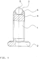
- a particularly advantageous development of the invention is characterized in that the attachment is designed as a ball, which is non-positively inserted in a central bore in the end face of the bolt-shaped element and that the ball partially protrudes from the end face of the element.
- the non-positive attachment of the ball in the hole can be done simply by choosing the diameter of the ball slightly larger than the diameter of the hole and the ball is simply pressed into the hole. The depth of the hole should be over half the ball diameter so that the ball partially protrudes from the hole after being pressed in. The ball is thus securely attached without additional means for securing its position being necessary.
- a particularly good attachment the ball is not required anyway, since it only has to be ensured that it cannot fall out during assembly of the screw on an assembly or a component and its transport to the assembly site.
- the ball is mainly loaded in the axial direction during the assembly of the assembly in the body, that is, the acting forces push the ball into the bore.
- end face of the bolt-shaped element is provided with a circumferential bevel, threading is further facilitated and at the same time it is prevented that the edge of the end face could possibly cause damage to the lacquer.
- the attachment is designed as a cap with a spherical front and an adjoining cylindrical region, the diameter of the cap and the cylindrical region being expediently chosen such that it corresponds at most to the diameter of the bolt-shaped element.
- the cap In order to be able to mount the cap easily, it is fastened non-positively and / or positively to a mandrel protruding from the end face of the bolt-shaped element.
- a further variant of the invention is characterized in that the attachment is designed as a mushroom, which is fixed in a bore in the end face of the bolt-shaped element in a force-locking manner or by gluing. It is expedient if the largest diameter of the mushroom corresponds at most to the diameter of the bolt-shaped element, so that, just as with the cap, the threading of the bolt-shaped elements into the openings in the Body is facilitated, it being advantageous if the end face of the attachment is curved in the shape of a truncated cone.
- the attachment consists of a plastic or a rubber-elastic material, whereby other materials can also be used, provided their elasticity is greater and / or their hardness is lower than that of the lacquer layer or the surface coating.
- welding screws 1 which are designed such that they can be fastened, for example, to assemblies of motor vehicles by welding.
- a rotationally symmetrical base plate 2 is formed on one end of the welding screw 1, which is either welded flat onto the assembly, or preferably by first passing the welding screw 1 through a hole in the assembly and then welding it.
- the end face 3 of the welding screw 1, which lies opposite the base plate 2 is provided with a central bore 4, into which a ball 5 is inserted in a non-positive manner in such a way that the ball partially protrudes from the end face 3.
- the ball 5 consists of a material which has a lower hardness than the coating material which surrounds an opening or bore into which the welding screw 1 is to be inserted during a later assembly process. For example, these can be holes in body parts that have already been painted. This means that the ball 5 can advantageously consist of a plastic or a rubber-elastic material.
- the frictional attachment of the ball 5 in the bore 4 can be done simply by choosing the diameter of the ball 5 slightly larger than the diameter of the bore 4 and the ball 5 is only pressed into it.
- the depth of the bore 4 should be over half the diameter of the ball 5, so that the ball 5 partially protrudes from the bore 4 after being pressed in. In this way, the ball 5 is securely attached without additional means for securing its position would be necessary.
- a particularly good attachment of the ball is not necessary anyway, since it only has to be ensured that it cannot fall out during assembly of the welding screw 1 on an assembly and its transport to the assembly site.
- the ball 5 is mainly loaded in the axial direction during the assembly of the assembly in the body, i.e. the acting forces push the ball 5 into the bore.
- the end face 3 of the welding screw 1 is provided with a peripheral chamfer 6.
- the diameter of the ball 5 is smaller than the outer diameter of the welding screw 1, at the beginning of the threading process, there is a greater scope which considerably facilitates the so-called "snapping" of a large number of welding screws 1 to be passed simultaneously through bores.
- the welding screws 1 provided with balls 5 can thus be used particularly advantageously in the assembly of complicated assemblies with a large number of fastening points, as is the case, for example, in automobile construction.
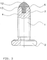
- FIG. 2 A variant of the invention can be seen from FIG. 2, in which the end face 3 opposite the base plate 2 of the welding screw 1 is provided with a cap 7 made of a plastic or a rubber-elastic material.
- the cap 7 has a spherical front 8 and an adjoining cylindrical region 9, the diameter of the cap 7 and the cylindrical region 9 being expediently chosen such that it corresponds at most to the diameter of the welding screw 1.
- This variant of the invention increases the scope when threading the welding screws 1 into the associated openings in the body and thereby facilitates the entire assembly process, as in the preferred variant with the ball 5.
- the end face 3 of the welding screw 1 is provided with a centrally projecting mandrel 10 which is to be inserted into a blind bore 11 within the cap 7.
- the diameter of the blind bore 11 is selected to be slightly smaller than the diameter of the mandrel 10.
- the mandrel can be provided with a collar which is to be snapped into an annular groove within the blind bore 11.
- the cap 7 does not necessarily have to be rotationally symmetrical with the cylindrical region 9 and the blind bore 11, since other shapes, such as e.g. a truncated cone, a pyramid or e.g. Longitudinal grooves in the blind bore 11 can be used with the same advantages.
- FIG. 3 Another variant of the invention is shown in Fig. 3, in which a mushroom 12 made of a plastic or a rubber-elastic material in the bore 4 in the end face 3 of the welding screw 1 is non-positively or by gluing.
- the attachment of the mushroom 12 takes place here only by the fact that its shaft 13 is pressed into the bore 4 in a force-fitting manner, it being possible to additionally glue the shaft 13.
- the largest diameter of the mushroom 12 should at most correspond to the diameter of the welding screw 1, so that the threading of the welding screws 1 into bores in the body is made easier, just like when the ball 5 or the cap 7 is used. It is advantageous if the mushroom 12 is frustoconical or spherical.
- the configuration of the welding screws 1 according to the invention greatly improves the assembly of prefabricated assemblies in car bodies, since on the one hand easy threading is made possible and on the other hand the risk of damage to paint layers or surface coatings is completely eliminated.
- the invention can also be used in a corresponding manner for connecting bolts with or without thread, welding bolts, fastening screws, centering pins or the like. be applied.
Landscapes
- Engineering & Computer Science (AREA)
- General Engineering & Computer Science (AREA)
- Mechanical Engineering (AREA)
- Connection Of Plates (AREA)
Applications Claiming Priority (2)
| Application Number | Priority Date | Filing Date | Title |
|---|---|---|---|
| DE4344626 | 1993-12-24 | ||
| DE19934344626 DE4344626A1 (de) | 1993-12-24 | 1993-12-24 | Befestigungselement |
Publications (1)
| Publication Number | Publication Date |
|---|---|
| EP0661464A1 true EP0661464A1 (fr) | 1995-07-05 |
Family
ID=6506330
Family Applications (1)
| Application Number | Title | Priority Date | Filing Date |
|---|---|---|---|
| EP94120474A Withdrawn EP0661464A1 (fr) | 1993-12-24 | 1994-12-22 | Elément de fixation |
Country Status (2)
| Country | Link |
|---|---|
| EP (1) | EP0661464A1 (fr) |
| DE (1) | DE4344626A1 (fr) |
Cited By (5)
| Publication number | Priority date | Publication date | Assignee | Title |
|---|---|---|---|---|
| FR2926045A1 (fr) * | 2008-01-09 | 2009-07-10 | Peugeot Citroen Automobiles Sa | Structure pour airbag et vehicule equipe de cette structure. |
| CN102720744A (zh) * | 2012-06-05 | 2012-10-10 | 宁波市北仑华申紧固件有限公司 | 一种紧固螺钉 |
| US9334894B2 (en) | 2012-08-29 | 2016-05-10 | Audi Ag | Fastening element with multiple joining directions and corresponding fastening arrangement for the fastening of an attachment part on a vehicle body |
| CN106122234A (zh) * | 2016-06-17 | 2016-11-16 | 浙江吉利罗佑发动机有限公司 | 一种双头螺柱防松措施及安装方法 |
| FR3050243A1 (fr) * | 2016-04-13 | 2017-10-20 | Snecma | Vis d’extraction pour le demontage de pieces assemblees |
Families Citing this family (3)
| Publication number | Priority date | Publication date | Assignee | Title |
|---|---|---|---|---|
| DE102007025888A1 (de) | 2007-06-01 | 2008-12-04 | Abc Umformtechnik Gmbh & Co. Kg | Anordnung zur Verbindung von Bauteilen durch Schrauben und Schweißen und Verfahren zur Herstellung einer solchen Verbindung |
| DE202011101557U1 (de) * | 2011-06-08 | 2012-09-13 | Erika Jankus Patent- Und Lizenzverwaltungs Gmbh | Flügelschraube |
| DE102024200246A1 (de) * | 2024-01-11 | 2025-07-17 | Volkswagen Aktiengesellschaft | Drehkopfeinheit für ein Drehkopfwerkzeug, Drehkopfwerkzeug und Verfahren zum Ausführen eines Bearbeitungsvorgangs an einer Öffnung eines Werkstücks sowie Zentrierschraubelement |
Citations (3)
| Publication number | Priority date | Publication date | Assignee | Title |
|---|---|---|---|---|
| GB953794A (en) * | 1959-12-12 | 1964-04-02 | G K N Screws And Fasteners Ltd | Improvements relating to screws |
| GB2017250A (en) * | 1978-03-22 | 1979-10-03 | Bosch Gmbh Robert | A Set Screw for a Speed Governor for a Fuel Injection Pump |
| FR2577286A3 (fr) * | 1985-02-12 | 1986-08-14 | Renault | Vis a bout pilote |
Family Cites Families (3)
| Publication number | Priority date | Publication date | Assignee | Title |
|---|---|---|---|---|
| DE1798509U (de) * | 1959-08-19 | 1959-10-22 | Markus Schmidt Tychsen Derrick | Verbindungselement fuer baukonstruktionen, insbesondere fuer kraene. |
| DD268745A1 (de) * | 1988-02-19 | 1989-06-07 | Fuerstenwalde Chem Tankanlagen | Selbstzentrierendes einschraubstueck |
| DE9209715U1 (de) * | 1992-07-20 | 1992-11-26 | Langer, Georg, 5828 Ennepetal | Spannschraube |
-
1993
- 1993-12-24 DE DE19934344626 patent/DE4344626A1/de not_active Withdrawn
-
1994
- 1994-12-22 EP EP94120474A patent/EP0661464A1/fr not_active Withdrawn
Patent Citations (3)
| Publication number | Priority date | Publication date | Assignee | Title |
|---|---|---|---|---|
| GB953794A (en) * | 1959-12-12 | 1964-04-02 | G K N Screws And Fasteners Ltd | Improvements relating to screws |
| GB2017250A (en) * | 1978-03-22 | 1979-10-03 | Bosch Gmbh Robert | A Set Screw for a Speed Governor for a Fuel Injection Pump |
| FR2577286A3 (fr) * | 1985-02-12 | 1986-08-14 | Renault | Vis a bout pilote |
Cited By (6)
| Publication number | Priority date | Publication date | Assignee | Title |
|---|---|---|---|---|
| FR2926045A1 (fr) * | 2008-01-09 | 2009-07-10 | Peugeot Citroen Automobiles Sa | Structure pour airbag et vehicule equipe de cette structure. |
| CN102720744A (zh) * | 2012-06-05 | 2012-10-10 | 宁波市北仑华申紧固件有限公司 | 一种紧固螺钉 |
| CN102720744B (zh) * | 2012-06-05 | 2014-11-19 | 宁波市北仑华申紧固件有限公司 | 一种紧固螺钉 |
| US9334894B2 (en) | 2012-08-29 | 2016-05-10 | Audi Ag | Fastening element with multiple joining directions and corresponding fastening arrangement for the fastening of an attachment part on a vehicle body |
| FR3050243A1 (fr) * | 2016-04-13 | 2017-10-20 | Snecma | Vis d’extraction pour le demontage de pieces assemblees |
| CN106122234A (zh) * | 2016-06-17 | 2016-11-16 | 浙江吉利罗佑发动机有限公司 | 一种双头螺柱防松措施及安装方法 |
Also Published As
| Publication number | Publication date |
|---|---|
| DE4344626A1 (de) | 1995-07-13 |
Similar Documents
| Publication | Publication Date | Title |
|---|---|---|
| DE69307077T2 (de) | Kugelgelenk und Herstellungsverfahren dafür | |
| EP0694465B1 (fr) | Carrosserie de véhicule automobile comportant une traverse structurelle | |
| DE69202484T2 (de) | Verfahren und Vorrichtung zur Befestigung von Platten an Raumfachwerken. | |
| DE202007011491U1 (de) | Vorrichtung zur Befestigung von Kunststoffteilen an einer Kraftfahrzeugkarosserie | |
| EP2019765B1 (fr) | Dispositif et procédé pour fixer un moteur d'essuie-glace sur une tringlerie d'essuie-glace | |
| DE2919411A1 (de) | Bremsscheibe fuer rad eines kraftfahrzeugs | |
| DE10155312A1 (de) | Verfahren zum Verbinden zweier Werkstücke | |
| EP0149492A2 (fr) | Charnière pour porte de véhicule automobile | |
| EP0661464A1 (fr) | Elément de fixation | |
| DE102014006088B4 (de) | Toleranzausgleichselement | |
| DE102020216324A1 (de) | Vorrichtung zum Ausgleichen von Toleranzen zwischen einem ersten Bauteil und einem zweiten Bauteil und Anordnung zum Ausgleichen von Toleranzen | |
| DE10219245B4 (de) | Verfahren zum Trennen einer Geberwelle eines Drehgebers von einer Antriebswelle | |
| DE102016013700A1 (de) | Schweißmutter | |
| DE68903826T2 (de) | Vorrichtung zum befestigen eines ausruestungsstueckes auf einem teil des innenaufbaus eines fahrzeuges in einer relativen stellung zum aussenaufbau. | |
| DE102019203051A1 (de) | Befestigungselement zum Reibschweißen sowie Verfahren zum Reibschweißen eines Befestigungselements an ein flächiges Werkstück | |
| EP1612432B1 (fr) | Dispositif de fixation pour habillage et méthode de fixation | |
| DE602005000697T2 (de) | Haltemittel und zugehöriges Fahrzeug | |
| EP0509355B1 (fr) | Ensemble pour charnière de portière de véhicule | |
| DE102023207479A1 (de) | Vorrichtung zum Ausgleichen von Toleranzen | |
| DE3510300A1 (de) | Befestigungsschraube, insbesondere fuer stossfaenger von kraftfahrzeugen | |
| DE19853411A1 (de) | Geteilter Stabilisator | |
| DE3836372C2 (fr) | ||
| DE10341033B4 (de) | Vorrichtung und Arbeitsverfahren zum Verbinden und Einstellen von mit Abstand zueinanderliegenden Bauteilen | |
| DE4223609A1 (de) | Vorrichtung zum Verbinden eines Lenkerarmes mit einem Lager | |
| DE102016222352A1 (de) | Schraubverbindung mit Toleranzausgleich, Kraftfahrzeug mit Schraubverbindung, Verfahren zum Verbinden zweier Bauteile mittels Schraubverbindung und Schraubvorrichtung |
Legal Events
| Date | Code | Title | Description |
|---|---|---|---|
| PUAI | Public reference made under article 153(3) epc to a published international application that has entered the european phase |
Free format text: ORIGINAL CODE: 0009012 |
|
| AK | Designated contracting states |
Kind code of ref document: A1 Designated state(s): DE FR GB NL |
|
| 17P | Request for examination filed |
Effective date: 19950809 |
|
| 17Q | First examination report despatched |
Effective date: 19961022 |
|
| STAA | Information on the status of an ep patent application or granted ep patent |
Free format text: STATUS: THE APPLICATION HAS BEEN WITHDRAWN |
|
| 18W | Application withdrawn |
Withdrawal date: 19970122 |