EP0663526A2 - Dispositif d'allumage pour un moteur à combustion interne - Google Patents
Dispositif d'allumage pour un moteur à combustion interne Download PDFInfo
- Publication number
- EP0663526A2 EP0663526A2 EP95100375A EP95100375A EP0663526A2 EP 0663526 A2 EP0663526 A2 EP 0663526A2 EP 95100375 A EP95100375 A EP 95100375A EP 95100375 A EP95100375 A EP 95100375A EP 0663526 A2 EP0663526 A2 EP 0663526A2
- Authority
- EP
- European Patent Office
- Prior art keywords
- voltage
- ignition
- set forth
- ignition coil
- ignition system
- Prior art date
- Legal status (The legal status is an assumption and is not a legal conclusion. Google has not performed a legal analysis and makes no representation as to the accuracy of the status listed.)
- Granted
Links
- 238000002485 combustion reaction Methods 0.000 title claims abstract description 12
- 238000004804 winding Methods 0.000 claims abstract description 63
- 230000015556 catabolic process Effects 0.000 claims abstract description 16
- 230000003247 decreasing effect Effects 0.000 description 9
- 238000010586 diagram Methods 0.000 description 7
- 238000010304 firing Methods 0.000 description 7
- 230000003321 amplification Effects 0.000 description 4
- 238000003199 nucleic acid amplification method Methods 0.000 description 4
- 239000000446 fuel Substances 0.000 description 3
- 238000012986 modification Methods 0.000 description 3
- 230000004048 modification Effects 0.000 description 3
- 230000006835 compression Effects 0.000 description 2
- 238000007906 compression Methods 0.000 description 2
- 230000000694 effects Effects 0.000 description 2
- 238000009434 installation Methods 0.000 description 2
- 238000000034 method Methods 0.000 description 2
- XEEYBQQBJWHFJM-UHFFFAOYSA-N Iron Chemical group [Fe] XEEYBQQBJWHFJM-UHFFFAOYSA-N 0.000 description 1
- 238000006243 chemical reaction Methods 0.000 description 1
- 230000000593 degrading effect Effects 0.000 description 1
- 230000001419 dependent effect Effects 0.000 description 1
- 230000006698 induction Effects 0.000 description 1
- 230000000977 initiatory effect Effects 0.000 description 1
- 238000004519 manufacturing process Methods 0.000 description 1
- 238000005259 measurement Methods 0.000 description 1
- 230000000116 mitigating effect Effects 0.000 description 1
- 230000002035 prolonged effect Effects 0.000 description 1
- 238000007493 shaping process Methods 0.000 description 1
Images


Classifications
-
- F—MECHANICAL ENGINEERING; LIGHTING; HEATING; WEAPONS; BLASTING
- F02—COMBUSTION ENGINES; HOT-GAS OR COMBUSTION-PRODUCT ENGINE PLANTS
- F02P—IGNITION, OTHER THAN COMPRESSION IGNITION, FOR INTERNAL-COMBUSTION ENGINES; TESTING OF IGNITION TIMING IN COMPRESSION-IGNITION ENGINES
- F02P3/00—Other installations
- F02P3/02—Other installations having inductive energy storage, e.g. arrangements of induction coils
- F02P3/04—Layout of circuits
- F02P3/055—Layout of circuits with protective means to prevent damage to the circuit, e.g. semiconductor devices or the ignition coil
- F02P3/0552—Opening or closing the primary coil circuit with semiconductor devices
-
- F—MECHANICAL ENGINEERING; LIGHTING; HEATING; WEAPONS; BLASTING
- F02—COMBUSTION ENGINES; HOT-GAS OR COMBUSTION-PRODUCT ENGINE PLANTS
- F02P—IGNITION, OTHER THAN COMPRESSION IGNITION, FOR INTERNAL-COMBUSTION ENGINES; TESTING OF IGNITION TIMING IN COMPRESSION-IGNITION ENGINES
- F02P3/00—Other installations
- F02P3/02—Other installations having inductive energy storage, e.g. arrangements of induction coils
Definitions
- the present invention relates generally to an ignition system for internal combustion engines, and more particularly to a so-called induction discharge non-contact type ignition system which interrupts a primary current flow through an ignition coil to produce a desired level of required secondary voltage for initiating an ignition arc through a spark plug.
- FIG. 9 shows a prior art ignition system similar to those disclosed in the above references.
- An igniter 20 has a darlington transistor 21 serving to turn on and off a primary current flowing through an ignition coil 22.
- the darlington transistor 21 is provided with two npn bipolar transistors.
- the ignition coil 22 has a primary winding 23 connected to a collector electrode of the darlington transistor 21 and a secondary winding 24 connected to a spark plug (not shown).
- a zener diode 25 is connected to the darlington transistor 21 for protecting the transistor 21 against the overvoltage.
- a breakdown voltage V D of the transistor 21 is determined based on a zener voltage V Z of the zener diode 25 which is selected to be about 350V in view of effective withstand voltage characteristics of the darlington transistor 21.
- the DLI system As shown in Fig. 10, has a high withstand voltage diode 100 Interposed between a primary winding 8 and a secondary winding 9 of an ignition coil 7 for preventing a sparking failure of a spark plug due to a secondary on-voltage induced in the secondary winding 9 from occurring at a time when a primary current is supplied to the ignition coil.
- the secondary on-voltage depends upon a secondary winding to primary winding turns ratio of the ignition coil.
- the ignition system taught in U.S.P. No. 3,824,977 has a secondary winding to primary winding turns ratio of an ignition coil ranging from 40 to 60 for increasing an ignition arc current produced through a spark plug to improve the sparking ability. Additionally, in the ignition system disclosed in U.S.P. No. 5,193,514, an ignition coil has a turns ratio of less than 70 for developing a voltage of at least 6 kV across electrodes of a spark plug. It will be noted that while conventional ignition coils commonly have a turns ratio of about 90, the ignition coils, as taught in the above references, have decreased turns ratios. These references, however, do not refer to a reduction in primary voltage of the ignition coil at al.
- V1 V2 / a
- a decrease in the turns ratio a to obtain a preselected level of the secondary voltage V2 will cause the primary voltage V1 to increase.
- the primary voltage V1 is, thus, affected by the zener voltage V Z so that it is increased only to 350 V.
- the required secondary voltage V r usually tends to be increased with the passing of time, thereby increasing the possibility of the above problems being encountered. Further, in recent years, a compression ratio of an internal combustion engine is often increased for producing high power and/or an air-fuel ratio is often controlled on a lean side for fuel economy. This will, however, cause the required secondary voltage V r to be increased, leading to a lack of the secondary voltage V2.
- an ignition system for an internal combustion engine which comprises an ignition coil including a primary winding and a secondary winding and a switching element for interrupting a current flow through the primary winding of the ignition coil at given timing.
- the ignition coil has a turns ratio a of the secondary to primary windings which satisfies the condition of V D ⁇ a > V r where V r is a required voltage of a spark plug mounted in the engine and V D is a breakdown voltage of the switching element which is greater than or equal to 450 V.
- the turns ratio a falls within a range of 40 to 80.
- the ignition coil is disposed within a cylindrical housing, inserted into a plug hole formed in the engine, having a diameter smaller than or equal to 30 mm.
- the ignition coil is of a magnetically open type.
- the ignition coil provides sparking energy to a spark plug installed in a cylinder of the engine without being transferred through a distributor.
- a secondary voltage of the ignition coil is greater than or equal to 28 kV.
- the switching element is provided with an insulated-gate bipolar transistor.
- a zener diode is further provided which is connected to the insulated-gate bipolar transistor for preventing overvoltage of the ignition coil.
- the breakdown voltage V D of the insulated-gate bipolar transistor is determined based on a breakdown voltage V Z of the zener diode.
- the zener diode is built in the insulated-gate bipolar transistor.
- the switching element may alternatively be provided with a MOSFET or a bipolar transistor.
- a distributor less ignition system for an internal combustion engine which comprises an ignition coil including a primary winding and a secondary winding and a switching element for interrupting a current flow through the primary winding of the ignition coil at given timing to supply ignition energy to a spark plug of the engine.
- the ignition coil has a turns ratio a of the secondary to primary windings which satisfies the condition V D ⁇ a > V r where V r is a required voltage of the spark plug of the engine and V D is a breakdown voltage of the switching element which is greater than or equal to 450 V.
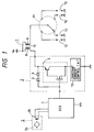
- the ignition control system for a four-cylinder internal combustion engine.
- the ignition control system generally includes an electronic control unit (ECU) 1, an igniter 3, an ignition coil 7, and a distributor 11.
- the ECU 1 includes a microcomputer, A/D converters, and wave-shaping circuits.
- an angular sensor 2 which includes a rotor 2a rotating according to the engine speed and a pick-up coil 2b detecting the passage of teeth formed on the rotor 2a.
- the igniter 3 is composed of an insulated-gate bipolar transistor (IGBT) 4, a pair of zener diodes 5 and 6 connected in series and oriented in opposite directions, and a constant current control circuit 13. Note that the IGBT 4 is expressed in the form of an equivalent circuit. To a gate terminal of the IGBT 4, the ECU 1 is connected to provide an ignition signal for turning on and off the IGBT 4. The zener diodes 5 and 6 are practically built into the IGBT 4 for reduction in size for an overall circuit structure.
- IGBT 4 insulated-gate bipolar transistor
- the zener diode 5 is arranged to restrict the voltage appearing between a gate and a collector of the IGBT 4 when a higher voltage is developed at the gate and a lower voltage is developed between the connector and an emitter.
- the zener diode 6 serves to prevent a primary voltage of the ignition coil 7 from being increased up to the overvoltage.
- the constant current control circuit 13 connects with the emitter of the IGBT 4 to control the primary current of the ignition coil 7 to a given constant current (6.5 A in this embodiment).
- the ignition coil 7 Includes a primary winding 8, a secondary winding 9, and an iron core 10.
- the primary winding 8 connects at one end with the collector of the IGBT 4 and at the other end with a battery source V B .
- the secondary winding 9 connects with a spark plug 12 of each cylinder through the distributor 11.
- an electric signal ie., an ignition signal
- IGBT 4 When an electric signal (ie., an ignition signal) is produced from the ECU 1 to apply the voltage to the gate of the IGBT 4, it will cause IGBT 4 to be turned on to produce a flow of the primary current through the primary winding 8 of the ignition coil 7.
- the primary current is held at a given current value (eg., 6.5 A) by the activities of the constant current control circuit 13.
- the primary current is interrupted intermittently to create a high level of the secondary voltage at the secondary winding 9 of the ignition coil 7 which, in turn, is applied to one of the spark plugs 12 through the distributor 11.
- the spark plug 12 strikes an ignition arc.
- the zener voltage V Z is set to 467 V which is higher than that of a typical darlington transistor.
- a typical bipolar transistor exhibits antipodal characteristics between an effective withstand voltage and a current amplification factor h FE . Because of this, when a given level of the current amplification factor h FE is required, it becomes difficult to increase the effective withstand voltage. However, an increase in the effective withstand voltage is easily achieved by the use of the IGBT 4 in this embodiment with the current amplification factor h FE being zero.
- the zener voltage V Z may, thus, be set to high level.
- the primary voltage V1 is low, then no current flows through the zener diode 6. However, if V1 is increased to V2/ a > V Z , then a current flow is produced through the zener diode 6 so that a current flows through the primary winding 8, thereby decreasing the secondary voltage V2.
- the zener voltage V Z is selected to be higher level which satisfies the condition of V Z ⁇ a > V r . Thus, even when the required secondary voltage V r is induced in the spark plug of the engine, the secondary voltage V2 is maintained at high level without producing a current flow through the primary winding 8.
- a decrease in the turns ratio a is accomplished by setting the zener voltage V Z to a higher level so as to meet the condition of V Z ⁇ a > V r .
- the turns ratio a falls within a range from 40 to 80 (preferably, 70).
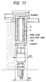
- an outer diameter of a cylindrical body 200 of an ignition coil needs to be less than 30 mm.
- the primary inductance L1 needs to be constant, that is, the number of turns N1 of the primary winding must be set to a given value.
- a decreased turns ratio of the ignition coil is achieved by decreasing the number of turns N2 of the secondary winding, thereby resulting in a reduced size of the ignition coil.
- the outer diameter of the ignition coil may be decreased.
- the shown ignition coil is, as discussed above, reduced in turns ratio, and is also of a magnetically open type for achieving a very small size facilitating easy installation in the plug hole.
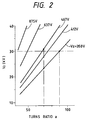
- Fig. 2 shows the relations between the turns ratio a of the ignition coil 7 and the secondary voltage V2 in terms of the zener voltages V Z (350, 412, 467, 637, and 875 V).
- the graph shows that as the zener voltage V Z and the turns ratio a are increased, the secondary voltage V2 becomes great.
- the use of the IGBT 4 allows the turns ratio a to be decreased from 70 to 65.
- the secondary voltage V2 which is conventionally 24.5 kV at a zener voltage V Z of 350 V, may be increased up to 32 kV under conditions that the turns ratio a is 70 and the zener voltage V Z is 467 V.
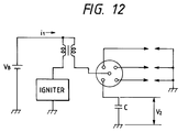
- Fig. 12 shows circuit arrangements for measuring the secondary voltage V2 represented in the graph of Fig. 2.
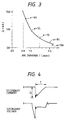
- Fig. 3 shows the relations between an arc current I2 and an arc duration for the turns ratio a when the primary current is interrupted.
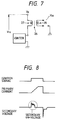
- the arc current I2 and the arc duration T are defined, as shown in Fig. 4 which shows a secondary current waveform and a secondary voltage waveform when the spark plug 12 is discharged.
- the graph In Fig. 3 shows that the arc duration T is prolonged according to an increase in the turns ratio a . Since the turns ratio a is set to 70 in this embodiment, the arc duration T will be about 1.2 msec.
- arc duration T Assuring good spark performance requires the arc duration T to be greater than or equal to 0.8 msec.
- the arc duration T of this embodiment is, as describe above, about 1.2 msec., which satisfies that condition.
- Fig. 3 shows that in order to meet the condition of the arc duration T > 0.8 msec., a turns ratio a of at least about 40 is necessary.
- an actual level of the secondary voltage V2 requires a margin for a required secondary voltage V r of 30 kV. Therefore, assuming that 3 kV is provided practically as the margin, a target level of the secondary voltage V2 at the required secondary voltage V r of 30 kV will be 33 kV.
- the target level of the secondary voltage V2 is derived with a turns ratio a of 75.
- the use of the IGBT 4 which turns on and off the primary current of the ignition coil 7 improves the effective withstand voltage, thereby allowing the zener voltage V Z to be increased.
- the turns ratio a may be decreased without reducing in level the secondary voltage V2 of the ignition coil 7. Since the number of turns of the primary winding 8 of the ignition coil 7 is fixed by the primary energy dependent upon the design, in order to decrease the turns ratio a , the number of turns of the secondary winding 9 must be decreased. The decrease in the turns ratio a will result in a reduced size of the spark plug, and also prevent the ignition plug 12 from smoldering. This offers good drivability.
- the turns ratio a of the ignition coil 7 may be reduced while maintaining the secondary voltage V2 above the required secondary voltage V r .
- the zener voltage V Z may be set to a value in a range from 450 to 825 V. In this case, good sparking performance is obtained as well as miniaturization of the ignition coil 7.
- Fig. 5 shows a circuit diagram which uses a MOSFET 15 having disposed therein the zener diode 6. This circuit arrangement also allows the zener voltage V Z of the zener diode 6 to be set to more than 450 V (preferably, 450 to 825 V) since a withstand voltage of the MOSFET 15 can be easily increased above that of a bipolar transistor.
- the ignition control system of this embodiment may be used with a so-called DLI (Distributor Less Ignition) system to supply sparking energy provided by the ignition coil 7 directly to the spark plug 12 of each cylinder without use of the distributor 11.
- DLI Distributor Less Ignition
- Fig. 6 shows the relation between a primary terminal voltage V10 (i.e., battery voltage V B ) of a primary winding 27 of an ignition coil 26, as shown in Fig. 7, and a voltage produced in the secondary winding 28 (i.e., a secondary on-voltage V20) in terms of the turns ratios a (40, 55, 70, 85, and 100).
- the secondary on-voltage shows a voltage produced based on a sparking signal from the ECU 1 during energization of the primary winding 8. When this voltage exceeds a given threshold level, it will cause the spark plug 12 to produce an improper ignition arc, leading to overadvanced firing.
- the overadvanced firing may be avoided by restricting the secondary on-voltage below 1.85 kV.
- the spark plug gap is 1.0 mm, the secondary voltage above 2.20 kV may cause the overadvanced firing.
- the turns ratio a is 70, the secondary voltage is always below 2.20 kV, thereby preventing the overadvanced firing.
- An ignition coil employed in the DLI system commonly has a high withstand voltage diode connected in series with a secondary winding for preventing the overadvanced firing due to the secondary on-voltage.
- the ignition control system of this embodiment eliminates the need for the high withstand voltage diode in the DLI system, resulting in greatly reduced manufacturing costs.
- the ignition control system of the above embodiment uses the IGBT 4 as a switching element, it may be replaced with another type of switching element such as a MOSFET or a bipolar transistor.
- Typical MOSFETs and bipolar transistors are, however, inferior to the IGBT 4 in current capacity per unit area. It is, thus, necessary to use a large size of element, which is disadvantageous for downsizing requirements.
- the bipolar transistors have a trade-off relation between effective withstand voltage and current amplification factor.
- a breakdown voltage over 450 V
- the size of the element needs to be 2.6 times in area that of the IGBT 4.
Landscapes
- Engineering & Computer Science (AREA)
- Chemical & Material Sciences (AREA)
- Combustion & Propulsion (AREA)
- Mechanical Engineering (AREA)
- General Engineering & Computer Science (AREA)
- Ignition Installations For Internal Combustion Engines (AREA)
Applications Claiming Priority (2)
| Application Number | Priority Date | Filing Date | Title |
|---|---|---|---|
| JP1753/94 | 1994-01-12 | ||
| JP175394 | 1994-01-12 |
Publications (3)
| Publication Number | Publication Date |
|---|---|
| EP0663526A2 true EP0663526A2 (fr) | 1995-07-19 |
| EP0663526A3 EP0663526A3 (fr) | 1996-05-08 |
| EP0663526B1 EP0663526B1 (fr) | 2010-03-31 |
Family
ID=11510344
Family Applications (1)
| Application Number | Title | Priority Date | Filing Date |
|---|---|---|---|
| EP95100375A Expired - Lifetime EP0663526B1 (fr) | 1994-01-12 | 1995-01-12 | Dispositif d'allumage pour un moteur à combustion interne |
Country Status (3)
| Country | Link |
|---|---|
| US (1) | US5609145A (fr) |
| EP (1) | EP0663526B1 (fr) |
| DE (1) | DE69536059D1 (fr) |
Cited By (2)
| Publication number | Priority date | Publication date | Assignee | Title |
|---|---|---|---|---|
| FR2751379A1 (fr) * | 1996-07-17 | 1998-01-23 | Sagem | Bobine d'allumage |
| EP0826879A3 (fr) * | 1996-09-03 | 1999-05-19 | Hitachi, Ltd. | Dispositif d'allumage constitué de bobine et de circuit d'allumage pour un moteur à combustion interne |
Families Citing this family (4)
| Publication number | Priority date | Publication date | Assignee | Title |
|---|---|---|---|---|
| US5775310A (en) * | 1996-12-24 | 1998-07-07 | Hitachi, Ltd. | Ignition device for an internal combustion engine |
| JP3740008B2 (ja) | 2000-10-11 | 2006-01-25 | 株式会社日立製作所 | 車載イグナイタ、絶縁ゲート半導体装置及びエンジンシステム |
| US20080257324A1 (en) * | 2006-12-22 | 2008-10-23 | Brp Us Inc. | Inductive ignition system for internal combustion engine |
| FR2919423B1 (fr) * | 2007-07-27 | 2009-09-04 | Renault Sas | Bobine d'allumage pourvue de moyens de mise a un potentiel faible d'un circuit magnetique |
Family Cites Families (5)
| Publication number | Priority date | Publication date | Assignee | Title |
|---|---|---|---|---|
| US3824977A (en) * | 1973-11-23 | 1974-07-23 | Gen Motors Corp | Internal combustion engine ignition system |
| DE3109650A1 (de) * | 1981-03-13 | 1982-09-23 | Robert Bosch Gmbh, 7000 Stuttgart | "aus einer induktiven last und der anoden-kathoden-strecke eines selbstsperrenden feldeffekttransistors bestehende serienschaltung" |
| DE3734080A1 (de) * | 1987-10-08 | 1989-04-20 | Beru Werk Ruprecht Gmbh Co A | Transistorzuendvorrichtung fuer eine brennkraftmaschine |
| JPH04143461A (ja) * | 1990-10-05 | 1992-05-18 | Honda Motor Co Ltd | 内燃機関の点火装置 |
| DE69128079T2 (de) * | 1991-07-04 | 1998-05-20 | Hitachi Ltd | Induktionsentladungsprinzip-Zündeinrichtung für eine innere Brennkraftmaschine |
-
1995
- 1995-01-12 DE DE69536059T patent/DE69536059D1/de not_active Expired - Lifetime
- 1995-01-12 US US08/371,702 patent/US5609145A/en not_active Expired - Lifetime
- 1995-01-12 EP EP95100375A patent/EP0663526B1/fr not_active Expired - Lifetime
Cited By (3)
| Publication number | Priority date | Publication date | Assignee | Title |
|---|---|---|---|---|
| FR2751379A1 (fr) * | 1996-07-17 | 1998-01-23 | Sagem | Bobine d'allumage |
| WO1998003791A1 (fr) * | 1996-07-17 | 1998-01-29 | Sagem S.A. | Bobine d'allumage |
| EP0826879A3 (fr) * | 1996-09-03 | 1999-05-19 | Hitachi, Ltd. | Dispositif d'allumage constitué de bobine et de circuit d'allumage pour un moteur à combustion interne |
Also Published As
| Publication number | Publication date |
|---|---|
| DE69536059D1 (de) | 2010-05-12 |
| EP0663526B1 (fr) | 2010-03-31 |
| EP0663526A3 (fr) | 1996-05-08 |
| US5609145A (en) | 1997-03-11 |
Similar Documents
| Publication | Publication Date | Title |
|---|---|---|
| US4502454A (en) | Ignition system for an internal combustion engine | |
| EP1316723A2 (fr) | Dispositif d'allumage pour un moteur à combustion interne | |
| US6539930B2 (en) | Ignition apparatus for internal combustion engine | |
| KR19990006589A (ko) | 다중 스파크 점화시스템 | |
| US4641626A (en) | Electronic ignition device for interval combustion engines | |
| US5609145A (en) | Internal combustion engine ignition system | |
| JPH0694864B2 (ja) | 内燃機関用点火装置 | |
| EP0715075A2 (fr) | Dispositif de détection de raté pour moteur à combustion interne | |
| CA2134815C (fr) | Methode de detection de rates d'allumage | |
| EP0521207A1 (fr) | Dispositif d'allumage du type à décharge inductive pour un moteur à combustion interne | |
| US6216530B1 (en) | Combustion state detecting device for an internal combustion engine | |
| US6082344A (en) | Ignition device for an internal combustion engine | |
| US20020144539A1 (en) | Ignition system with ion current detecting circuit | |
| JPS61178561A (ja) | 内燃機関の点火装置 | |
| JP3528296B2 (ja) | 内燃機関用点火装置 | |
| US5347856A (en) | Misfire detector device for use in an internal combustion engine | |
| JPH0344228B2 (fr) | ||
| EP0665376B1 (fr) | Dispositif de détection de raté d'allumage | |
| JP2000009010A (ja) | 内燃機関用点火装置 | |
| JPS61258968A (ja) | 内燃機関 | |
| JPH04209968A (ja) | 内燃機関の点火装置 | |
| JP3619073B2 (ja) | 内燃機関用燃焼状態検知装置 | |
| KR200240258Y1 (ko) | 점화플러그의전극손상방지를위한동시점화장치 | |
| SU714037A1 (ru) | Электронна система зажигани | |
| JP2525971B2 (ja) | 火花点火機関の失火検出装置 |
Legal Events
| Date | Code | Title | Description |
|---|---|---|---|
| PUAI | Public reference made under article 153(3) epc to a published international application that has entered the european phase |
Free format text: ORIGINAL CODE: 0009012 |
|
| AK | Designated contracting states |
Kind code of ref document: A2 Designated state(s): DE FR GB IT |
|
| PUAL | Search report despatched |
Free format text: ORIGINAL CODE: 0009013 |
|
| AK | Designated contracting states |
Kind code of ref document: A3 Designated state(s): DE FR GB IT |
|
| 17P | Request for examination filed |
Effective date: 19960605 |
|
| 17Q | First examination report despatched |
Effective date: 19961128 |
|
| RAP1 | Party data changed (applicant data changed or rights of an application transferred) |
Owner name: DENSO CORPORATION |
|
| GRAP | Despatch of communication of intention to grant a patent |
Free format text: ORIGINAL CODE: EPIDOSNIGR1 |
|
| GRAS | Grant fee paid |
Free format text: ORIGINAL CODE: EPIDOSNIGR3 |
|
| GRAA | (expected) grant |
Free format text: ORIGINAL CODE: 0009210 |
|
| AK | Designated contracting states |
Kind code of ref document: B1 Designated state(s): DE FR GB IT |
|
| REG | Reference to a national code |
Ref country code: GB Ref legal event code: FG4D |
|
| REF | Corresponds to: |
Ref document number: 69536059 Country of ref document: DE Date of ref document: 20100512 Kind code of ref document: P |
|
| REG | Reference to a national code |
Ref country code: GB Ref legal event code: 746 Effective date: 20101130 |
|
| PLBE | No opposition filed within time limit |
Free format text: ORIGINAL CODE: 0009261 |
|
| STAA | Information on the status of an ep patent application or granted ep patent |
Free format text: STATUS: NO OPPOSITION FILED WITHIN TIME LIMIT |
|
| 26N | No opposition filed |
Effective date: 20110104 |
|
| PGFP | Annual fee paid to national office [announced via postgrant information from national office to epo] |
Ref country code: DE Payment date: 20140122 Year of fee payment: 20 |
|
| PGFP | Annual fee paid to national office [announced via postgrant information from national office to epo] |
Ref country code: FR Payment date: 20140123 Year of fee payment: 20 Ref country code: IT Payment date: 20140128 Year of fee payment: 20 |
|
| PGFP | Annual fee paid to national office [announced via postgrant information from national office to epo] |
Ref country code: GB Payment date: 20140121 Year of fee payment: 20 |
|
| REG | Reference to a national code |
Ref country code: DE Ref legal event code: R071 Ref document number: 69536059 Country of ref document: DE |
|
| REG | Reference to a national code |
Ref country code: GB Ref legal event code: PE20 Expiry date: 20150111 |
|
| PG25 | Lapsed in a contracting state [announced via postgrant information from national office to epo] |
Ref country code: GB Free format text: LAPSE BECAUSE OF EXPIRATION OF PROTECTION Effective date: 20150111 |