EP0664104B1 - Cathéter à ballon d'obturation pour anéurismes ou vaisseaux latéraux - Google Patents
Cathéter à ballon d'obturation pour anéurismes ou vaisseaux latéraux Download PDFInfo
- Publication number
- EP0664104B1 EP0664104B1 EP95400059A EP95400059A EP0664104B1 EP 0664104 B1 EP0664104 B1 EP 0664104B1 EP 95400059 A EP95400059 A EP 95400059A EP 95400059 A EP95400059 A EP 95400059A EP 0664104 B1 EP0664104 B1 EP 0664104B1
- Authority
- EP
- European Patent Office
- Prior art keywords
- delivery
- occluding
- balloon
- exit port
- vessel
- Prior art date
- Legal status (The legal status is an assumption and is not a legal conclusion. Google has not performed a legal analysis and makes no representation as to the accuracy of the status listed.)
- Expired - Lifetime
Links
Images





Classifications
-
- A—HUMAN NECESSITIES
- A61—MEDICAL OR VETERINARY SCIENCE; HYGIENE
- A61M—DEVICES FOR INTRODUCING MEDIA INTO, OR ONTO, THE BODY; DEVICES FOR TRANSDUCING BODY MEDIA OR FOR TAKING MEDIA FROM THE BODY; DEVICES FOR PRODUCING OR ENDING SLEEP OR STUPOR
- A61M25/00—Catheters; Hollow probes
- A61M25/10—Balloon catheters
- A61M25/1002—Balloon catheters characterised by balloon shape
-
- A—HUMAN NECESSITIES
- A61—MEDICAL OR VETERINARY SCIENCE; HYGIENE
- A61B—DIAGNOSIS; SURGERY; IDENTIFICATION
- A61B17/00—Surgical instruments, devices or methods
- A61B17/12—Surgical instruments, devices or methods for ligaturing or otherwise compressing tubular parts of the body, e.g. blood vessels or umbilical cord
- A61B17/12022—Occluding by internal devices, e.g. balloons or releasable wires
-
- A—HUMAN NECESSITIES
- A61—MEDICAL OR VETERINARY SCIENCE; HYGIENE
- A61B—DIAGNOSIS; SURGERY; IDENTIFICATION
- A61B17/00—Surgical instruments, devices or methods
- A61B17/12—Surgical instruments, devices or methods for ligaturing or otherwise compressing tubular parts of the body, e.g. blood vessels or umbilical cord
- A61B17/12022—Occluding by internal devices, e.g. balloons or releasable wires
- A61B17/12027—Type of occlusion
- A61B17/12036—Type of occlusion partial occlusion
-
- A—HUMAN NECESSITIES
- A61—MEDICAL OR VETERINARY SCIENCE; HYGIENE
- A61B—DIAGNOSIS; SURGERY; IDENTIFICATION
- A61B17/00—Surgical instruments, devices or methods
- A61B17/12—Surgical instruments, devices or methods for ligaturing or otherwise compressing tubular parts of the body, e.g. blood vessels or umbilical cord
- A61B17/12022—Occluding by internal devices, e.g. balloons or releasable wires
- A61B17/12027—Type of occlusion
- A61B17/1204—Type of occlusion temporary occlusion
-
- A—HUMAN NECESSITIES
- A61—MEDICAL OR VETERINARY SCIENCE; HYGIENE
- A61B—DIAGNOSIS; SURGERY; IDENTIFICATION
- A61B17/00—Surgical instruments, devices or methods
- A61B17/12—Surgical instruments, devices or methods for ligaturing or otherwise compressing tubular parts of the body, e.g. blood vessels or umbilical cord
- A61B17/12022—Occluding by internal devices, e.g. balloons or releasable wires
- A61B17/12099—Occluding by internal devices, e.g. balloons or releasable wires characterised by the location of the occluder
- A61B17/12109—Occluding by internal devices, e.g. balloons or releasable wires characterised by the location of the occluder in a blood vessel
- A61B17/12113—Occluding by internal devices, e.g. balloons or releasable wires characterised by the location of the occluder in a blood vessel within an aneurysm
-
- A—HUMAN NECESSITIES
- A61—MEDICAL OR VETERINARY SCIENCE; HYGIENE
- A61B—DIAGNOSIS; SURGERY; IDENTIFICATION
- A61B17/00—Surgical instruments, devices or methods
- A61B17/12—Surgical instruments, devices or methods for ligaturing or otherwise compressing tubular parts of the body, e.g. blood vessels or umbilical cord
- A61B17/12022—Occluding by internal devices, e.g. balloons or releasable wires
- A61B17/12131—Occluding by internal devices, e.g. balloons or releasable wires characterised by the type of occluding device
- A61B17/12136—Balloons
-
- A—HUMAN NECESSITIES
- A61—MEDICAL OR VETERINARY SCIENCE; HYGIENE
- A61B—DIAGNOSIS; SURGERY; IDENTIFICATION
- A61B17/00—Surgical instruments, devices or methods
- A61B17/12—Surgical instruments, devices or methods for ligaturing or otherwise compressing tubular parts of the body, e.g. blood vessels or umbilical cord
- A61B17/12022—Occluding by internal devices, e.g. balloons or releasable wires
- A61B17/12131—Occluding by internal devices, e.g. balloons or releasable wires characterised by the type of occluding device
- A61B17/12181—Occluding by internal devices, e.g. balloons or releasable wires characterised by the type of occluding device formed by fluidized, gelatinous or cellular remodelable materials, e.g. embolic liquids, foams or extracellular matrices
- A61B17/12186—Occluding by internal devices, e.g. balloons or releasable wires characterised by the type of occluding device formed by fluidized, gelatinous or cellular remodelable materials, e.g. embolic liquids, foams or extracellular matrices liquid materials adapted to be injected
-
- A—HUMAN NECESSITIES
- A61—MEDICAL OR VETERINARY SCIENCE; HYGIENE
- A61B—DIAGNOSIS; SURGERY; IDENTIFICATION
- A61B17/00—Surgical instruments, devices or methods
- A61B17/00491—Surgical glue applicators
-
- A—HUMAN NECESSITIES
- A61—MEDICAL OR VETERINARY SCIENCE; HYGIENE
- A61M—DEVICES FOR INTRODUCING MEDIA INTO, OR ONTO, THE BODY; DEVICES FOR TRANSDUCING BODY MEDIA OR FOR TAKING MEDIA FROM THE BODY; DEVICES FOR PRODUCING OR ENDING SLEEP OR STUPOR
- A61M25/00—Catheters; Hollow probes
- A61M25/10—Balloon catheters
- A61M2025/1043—Balloon catheters with special features or adapted for special applications
- A61M2025/105—Balloon catheters with special features or adapted for special applications having a balloon suitable for drug delivery, e.g. by using holes for delivery, drug coating or membranes
-
- A—HUMAN NECESSITIES
- A61—MEDICAL OR VETERINARY SCIENCE; HYGIENE
- A61M—DEVICES FOR INTRODUCING MEDIA INTO, OR ONTO, THE BODY; DEVICES FOR TRANSDUCING BODY MEDIA OR FOR TAKING MEDIA FROM THE BODY; DEVICES FOR PRODUCING OR ENDING SLEEP OR STUPOR
- A61M25/00—Catheters; Hollow probes
- A61M25/10—Balloon catheters
- A61M2025/1043—Balloon catheters with special features or adapted for special applications
- A61M2025/1052—Balloon catheters with special features or adapted for special applications for temporarily occluding a vessel for isolating a sector
-
- A—HUMAN NECESSITIES
- A61—MEDICAL OR VETERINARY SCIENCE; HYGIENE
- A61M—DEVICES FOR INTRODUCING MEDIA INTO, OR ONTO, THE BODY; DEVICES FOR TRANSDUCING BODY MEDIA OR FOR TAKING MEDIA FROM THE BODY; DEVICES FOR PRODUCING OR ENDING SLEEP OR STUPOR
- A61M25/00—Catheters; Hollow probes
- A61M25/10—Balloon catheters
- A61M2025/1043—Balloon catheters with special features or adapted for special applications
- A61M2025/1072—Balloon catheters with special features or adapted for special applications having balloons with two or more compartments
Definitions
- the present invention relates to apparatus for delivering occluding agents through the opening in a blood vessel wall and into the aneurysm chamber or into a peripheral vessel, and in particular by introducing a balloon catheter, inflating the balloon to seal the blood vessel lumen around the vessel opening, and delivering the occluding agent through the opening to prevent loss of occluding agent into the blood vessel during such delivery and until in situ stabilization of the occluding agent as an occluding cast shaped to retain the patency of the blood vessel at the occluded opening.
- aneurysms in weakened blood vessel walls, particularly in arterial blood vessels, often presents a life threatening risk to a patient. This is particularly true in blood vessels serving the heart, brain and other vital organs.
- aneurysms may rupture, causing internal bleeding and loss of blood pressure or become the source of clots that may become dislodged and are borne by moving blood to other sites where they restrict blood flow.
- the rupture may lead to severe loss of pressure and rapid death.
- the pooling of blood may lead to pressure on brain cells and result in a stroke.
- a pair of catheter borne, detachable balloons are provided that are intended to be placed in the aneurism sac, inflatable with one balloon inside the other, and inflated to fill with one material or polymerize another material in the outer balloon in a shape conforming to the aneurism sac, so that the catheters may be detached with the balloons remaining in place.
- polymerizable material appears to be directed out of multiple holes in the outer balloon and into contact with the wall of the aneurism to bond the balloons and wall together.
- a catheter borne sleeve is proposed to be placed across and within the depicted wide mouth opening of an aneurism to block the mouth and serve as an alternative, intraluminal blood vessel.
- the sleeve is attached at either end to a pair of expandable stents which are introduced by a double balloon catheter and expanded upon inflation of the balloons.
- the expanded stents stabilize the sleeve ends against patent blood vessel walls.
- an apparent risk lies in detachment of one or both of the stents from contact with the blood vessel walls over time.
- the stents fibrose in, the fibrosis may restrict blood flow and lead to further complications. Many blood vessels would appear to be too small to benefit from this approach due to the necessary size of the components and introducing apparatus.
- Spaced apart, double balloon catheters are also proposed for use in temporarily occluding blood vessels to introduce a therapeutic agent in treating blood vessel intima injured in balloon angioplasty procedures, as disclosed in U.S. Patent No. 4,832,688.
- DE-A-3227575 which is used as basis for the preamble of claim 1 discloses another spaced apart balloon catheter for delivery an occluding agent.
- single or co-axially disposed double balloon catheters of the type disclosed in U.S. Patent Nos. 5,049,132, 5,087,244, 5,112,305, and 5,213,576 are described for distributing therapeutic agents through side wall holes in the outermost balloon to vessel walls to treat an atherosclerotic plaque or to induce penetration of the agent into the vessel wall to treat a vessel wall tumor or for applying heparin post-operatively at the site of an angioplasty procedure.
- These balloon catheters infuse therapeutic agents into the vessel itself and are not suited to the introduction of an occluding agent of a type that would also occlude an aneurysm chamber or branch vessel.
- a need remains for an apparatus for intraluminally occluding aneurysms in a main blood vessel wall that is simple to practice, does not threaten the integrity of the adjacent main blood vessel, and wherein main vessel patency is rapidly restored.
- a need also exists for such an apparatus which may be used to seal off and occlude a peripheral vessel feeding an aneurysm or for other reasons, e.g. the preparation of a vein for use as an arterial bypass section without invasive surgery.
- the present invention as characterized in claim 1 provides an elongated occluding balloon catheter for delivering an occluding agent.
- Prefered embodiments are further specified in the dependent claims
- the reduced leakage of occluding agent back into the main vessel decreases the risk of vessel blockage and/or stenosis and resultant tissue ischemia.
- Patient comfort is increased and cost of the intensive care treatment is reduced by the shortened time and reduction of exposure to the occluding agent.
- the balloon catheter 10 of the present invention includes a length of multi-lumen flexible tubing forming a catheter body 12 having a proximal end segment 14 and a distal end segment 16.
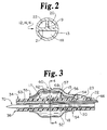
- the catheter body 12 is preferably formed with a plurality of axially extending, co-linear passageways or lumens, e.g. the three lumens 18, 20 and 22 depicted in the cross section view of Figure 2 (and in further views) which are coupled to structure in the proximal and distal segments to function as a balloon inflation/deflation lumen and/or a guide wire lumen and as one or two delivery lumens.
- the three lumens 18, 20 and 22 can be configured to deliver a single form of occluding agent in one embodiment of the invention or to deliver two separate components of an occluding agent, e.g. a catalyst and an active ingredient, in a further embodiment of the invention as described in greater detail hereafter.
- one lumen may be used to vent or aspirate through the opening to assist in filling the aneurysm chamber or branch vessel with the single occluding agent.
- Four lumens may also be provided to deliver the two components or perform other functions.
- the tubing of the catheter body 12 may be extruded from flexible plastic materials, e.g. thermoplastics, polyvinyl chlorides, polyethylenes, polyurethanes, polyesters, polypropylenes or the like as is well known in the balloon catheter art.
- the catheter body may be extruded or formed with a variety of lumen cross sections, including circular or elliptic lumens (as shown in Figure 6) or in a co-axial configuration (as described with reference to Figures 9 - 11) or with the pie-shaped lumens depicted in Figure 2.
- lumens 18, 20 and 22 are separated by webs 19 and 21 and confined in an outer tube 13.
- Lumen 18 is larger in cross section in order to accommodate a guide wire 70 shown in cross section.
- Lumens 20 and 22 are oriented together on one side to facilitate their alternate employment as delivery or venting lumens in the various embodiments described below.
- the lumens 18, 20 and 22 are coupled through a manifold 32 at the catheter body proximal end segment 14 to a catheter proximal end connector assembly 26.
- One of the lumens, e.g. lumen 18, is coupled through manifold 32 to a single lumen tube 30 and proximally terminates in a fitting 28 into the aperture 24 of which a guide wire 70 may be inserted.
- the guide wire lumen 18 is not employed for any other function, although it may also be employed as the balloon inflation/deflation lumen in other embodiments.
- the second lumen 20 is coupled through manifold 32 to a tube 42 which is coupled in turn to a valve adaptor 40.
- the second lumen 20 may be coupled internally to the balloon 52 to function in one embodiment as an inflation/deflation lumen when it is fitted to a source of pressurized fluid (not shown) attached at adaptor fitting 38.
- the lumen 20 may be in communication with a further delivery exit or venting port 60' adjacent to delivery exit port 60 and employed to deliver a component of a two component occluding agent or as an aspiration and/or venting lumen.
- the third lumen 22 is coupled through manifold 32 to a tube 50 which is coupled in turn to a valve adaptor 48.
- the third lumen 22 may be coupled internally at the proximal junction 54 of the balloon 52 with the lead body 12 through an elastic tube extension formed either inside or outside the balloon in various embodiments and extending along the outer wall of the balloon 52 to a delivery exit port 60 positioned midway down the length of the balloon 52.
- the third lumen 22 functions in all of the embodiments as a conduit for the delivery of a contrast medium or occluding agent, as described hereafter, upon positioning of the delivery exit port with respect to the opening of an aneurysm and inflation of the balloon 52.
- the third lumen may also be employed to introduce further catheters or devices into proximity with the opening 60 as described below.
- the balloon catheter 10 terminates at its distal end junction 55 with a soft tip 34 and a tip aperture 36 through which the guide wire 70 may extend during introduction of the catheter 10 and positioning of the balloon 52 alongside the aneurysm.
- the distal end segment 16 of the catheter body 12 is also provided with first and second radiopaque markers 15 and 17 which are located with respect to the delivery exit port 60 to assist in aligning it to the opening of an aneurysm or a branch vessel during introduction and orientation of the distal end segment 16. Any of the well known techniques may be employed for arterial and venous introduction of the catheter 10, with or without use of a surrounding introduction catheter (not shown) or the guide wire 70.
- Figures 3 and 4A depict in a partial side cross section view and end view, one embodiment of the construction of the balloon 52 in relation to the catheter body 12, its lumens 18, 20, 22, and the tube extension 56 leading to the delivery exit port 60.
- the lumens 20 and 22 are filled proximal to the distal aperture 36 to isolate the lumens and allow their use to deliver occluding agent and inflation fluid respectively.
- the inflation/deflation lumen 20 terminates and is filled more distally within the distal junction 55 of the balloon 52 with the outer surface of the lead body 12.
- the portion of the inflation/deflation lumen 20 within the balloon 52 has a number of spaced inflation/deflation holes 58 through the outer wall of the catheter body 12 to the interior space of the balloon 52. Inflation and deflation of balloon 52 are accomplished by applying and withdrawing pressurized fluid to and from the lumen 20 through the valve adaptor 40 in a manner well known in the art.
- the delivery lumen 22 is coupled by through hole 23 to the lumen 57 of delivery tube extension 56.
- the delivery tube extension 56 is formed of a flexible, thin walled tube cemented alongside the balloon 52 externally to the balloon wall for the full length of the balloon 52 between the proximal and distal junctions 54 and 55.
- the through hole 23 extends through the side wall of delivery tube extension 56, which is cemented proximally to itself and the surface of the catheter body distal end segment 14, and makes a communication between the delivery tube extension lumen 57 and delivery lumen 22.
- the delivery tube extension lumen 57 is stopped up or filled, or adhered to itself, at its distal end lumen 62 distal to the delivery exit port 60 formed in its external facing wall.
- the guide wire lumen 18 is open through the soft tip 34, which is preferably tapered in a manner well known in the balloon catheter art, and distal aperture 36.
- the balloon 52 is preferably formed of a radiation cross-linked polyolefin, e.g.polyethylene, which does not readily adhere to the occluding agent contacting it during delivery and formation of the occluding cast and attached to the exterior surface of the catheter body 12 by adhesive or thermal bonding or welding at the proximal and distal junctions 54 and 55 in a manner well known in the art of fabricating miniature balloon catheters.
- the delivery extension tube may be formed of a thin walled TEFLON® polyethylene tube and adhered to the balloon 52 by adhesive or thermal bonding or welding
- the balloon and delivery extension tube may also be coated with a release agent when fabricated of certain materials more prone to stick to the particular delivery agent.
- FIG. 4B it depicts, in an end cross section view conforming generally to Figure 4A, the above described features of the construction of the distal end segment 16 and balloon 52 in accordance with a fabrication variation that may be employed in the first embodiment and is also depicted in Figure 7.
- the delivery exit port 60 is formed in the outer wall of the balloon 52, and the delivery tube extension 56 is formed during balloon wall extrusion of the tubular shaped balloon.
- the exit port 60 is formed in the delivery tube extension 56 communicating with the lumen therein extending along the balloon 52 back to the proximal junction 54 and the through hole 23, as also shown in cross section in conjunction with the further embodiment of Figure 7.
- the orientation of the delivery exit port 60 to the blood vessel opening is preferably determined through the use of the radiopaque markers 15 and 17 around the port 60 which may be observed during introduction and position through fluoroscopy.
- the proper seal afforded by the inflated balloon may be verified in the further steps of inflating the balloon 52, injecting a contrast medium through the delivery lumen 22 and exit port 60 after orienting the delivery exit port 60 to a trial position and observing the filling of the aneurysm as well as the absence of its leakage down the blood vessel lumen when it is properly oriented.
- a radiopaque tip probe may be introduced down the delivery lumen 22 and observed as it exits the exit port 60 and enters the aneurysm chamber or a pressure measurement may be taken.
- a liquid occluding agent is preferably introduced into the chamber of the aneurysm where it reacts with blood or tissue or solidifies to fill the space.
- occluding agents may include cross-linked collagen implant fibrils which may be mixed with contrast media and chemical buffers of the types described in the 718 patent.
- a liquid or paste collagen is available under the name HELIOSTAT®.
- a further liquid thrombin mixture is available under the name THROMBOSTAT®.
- Such thrombin and collagen including mixtures form an occluding cast by thrombus formation.
- liquid, single component, occluding agents include methyl cyanoacrylate adhesives or 2-hydroxyethyl methylacrylate (HEMA) which set on contact with body fluids, e.g. of the type described in U.S. Patent No. 4,207,891 directed to occluding Fallopian tubes.
- HEMA 2-hydroxyethyl methylacrylate
- liquid silicone rubber may be used.
- Solid, single component, occluding agents may also be used in solid fibrous or particulate form that may be delivered through the vessel opening to form a solid mass of thrombus.
- the occluding agent is effective to coagulate blood around the fibers or particles and to form the thrombus mass within the aneurysm chamber or peripheral vessel to function as a solid occluding cast.
- Such occluding agents may also include one of the group of particulate compounds comprising polyvinyl alcohol (PVA), IVALON®, and GELL FOAM which are reactive to blood to coagulate it on contact, as described by Purdy in "Pre-Operative Embolization of Cerebral Arteriovenous Malformations with Polyvinyl Alcohol Particles", AJNR 11:501-510, May/June, 1990.
- PVA polyvinyl alcohol
- IVALON® IVALON®
- GELL FOAM GELL FOAM
- a solid occluding device or devices may be introduced through the lumen 22, out the delivery exit port 60 and through the adjoining vessel opening.
- the wire coils described in the above referenced 437 patent may be so introduced, while the balloon 52 is inflated, to fill the aneurysm chamber or branch vessel from the vessel opening.
- a plurality of such coils entwine or catch on one another and the aneurysm or vessel side walls to provide acute fixation and encourage the formation of a mass of thrombus that forms the occluding cast.
- FIG. 3 and 4A - 4B A further feature of the invention is depicted in Figures 3 and 4A - 4B which allows the use of the balloon catheter 10 with certain occluding agents that are liquid until they are exposed to irradiating illumination of a frequency which causes the occluding agent to solidify.
- a miniature probe or optical fiber 66 having a light diffuser or lens 68 at its distal end may be introduced down the lumen 22 (or lumen 20) and positioned to radiate light of the required frequency toward the opening 60.
- the catheter body 12 and balloon 52 may be transmissive of the frequency of radiation emitted, so that it falls upon occluding agent after it is delivered through the delivery exit port 60.
- the balloon catheter 10 may be rotated within the vessel after the occluding agent is delivered to seal the aneurysm or branch vessel opening with the inflated balloon 52.
- the optical fiber 66 and diffuser 68 may be oriented to emit radiation through the catheter body distal end segment 16 and balloon 52 and toward the blood vessel opening to effect the curing of the occluding agent and the formation of the occluding cast.
- the optical fiber 66 and diffuser 68 are depicted preferably extending down the inflation/deflation lumen 20 and optionally down the delivery lumen 22, respectively.
- the optical fiber 66 and probe 68 may be extended down the inflation/deflation lumen 18 or the aspirating/venting lumens of the other embodiments as well.
- the occluding agent preferably comprises one of the group of light reactive compounds including urethane oligomer/(meth) acrylate monomer blends reactive to light in the ultraviolet range and particularly the compound Dymax 136-M® which is reactive to ultraviolet light of a frequency of 300-400 nanometers.
- the compound Dymax 136-M® which is reactive to ultraviolet light of a frequency of 300-400 nanometers.
- Such compounds and light sources for their curing are described in the Dymax MD selector guide, Dymax data sheets and the Dymax 10M catalog.
- the lumens 18, 20 and 22 may be selectively configured to accommodate a two component occluding agent in a further embodiment of the invention depicted in partial cross section, elongated views of the distal end segment 16 in Figures 5 and 7, and in their respective end cross-section views in Figures 6 and 8.
- a further delivery exit port 60' and delivery tube lumen 61' extending from lumen 20 and through its wall in the catheter body distal end segment 16 closely adjacent to the delivery exit port 60 coupled to the delivery lumen 20.
- the guide wire lumen 18 as the inflation/deflation lumen and to provide inflation/deflation holes 58 through its wall into the interior space of the balloon 52.
- a self sealing valve 46 which is penetrable by the guide wire 70 is formed adjacent to the distal aperture 36.
- Such a self sealing valve 46 provides sufficient sealing against inflation pressure to allow inflation of the balloons 52 when the guide wire 70 is or is not extending through the valve 46 and may be of the type described in U.S. Patent No. 5,085,635 to Cragg.
- the lumen 20 is coupled to the lumen 61' of a further delivery tube extension 56' extending to the additional delivery exit port 60'.
- the further delivery tube extension 56' may be formed internal to the balloon or external to the balloon as a separate tube, as described above.
- the balloon 52 depicted in Figures 6 and the preceding figures is generally cylindrical, encircling and extending along the catheter body distal end segment 16, so that the delivery exit port(s) are laterally displaced with the expanding balloon during inflation.
- the delivery exit port(s) 60, 60' are formed through the catheter body distal end segment 16, and an alternate balloon structure 52' is attached around only a major circumferential arc of the segment 16.
- the alternate balloon 52' configurations are depicted in a partial cross section, elongated view and end views of the distal end segment 16 in Figures 7, 8A, 8B and 8C.
- alternate balloon 52' is formed along only a major circumferential section of the distal end segment 16 ( Figures 8A and 8B) or a minor circumferential interior section of the tubular balloon is adhered along the outer surface of tube 13 ( Figure 8C) so that the balloon 52' only inflates around the major circumference of the distal end segment 16.
- the delivery exit ports 60, 60' are formed through the outer tube 13 of the segment 16 in the minor circumferential section thereof in direct communication with the lumens 22 and 20 formed therein.
- the delivery exit ports 60 and 60', as shown in Figures 7 and 8C are thus directly made to the lumens 22 and 20, respectively, through the adhered balloon wall 52' and outer tube 13.
- the balloon 52' is inflated and deflated through the openings 58 made in the side wall of the catheter body distal end segment 16 to the lumen 18, which also functions as the guide wire lumen.
- the alternate balloon 52' can be formed to have alternate shapes when inflated.
- Each of the balloons 52' are as roughly semi-circular and surrounding a major arc of the circumference of the distal end segment 16.
- the delivery exit ports 60 and 60' are formed in a minor circumferential arc or section of the distal end segment 16 of the catheter body 12.
- the balloon 52' forms a U-shaped perfusion channel 53, when inflated, along its length opposite to the minor section where the exit ports 60 and 60' are located.
- This alternate shape depicted in Figure 8B allows the balloon 52' to form the perfusion channel 53 with the blood vessel wall through which blood may continue to flow after the balloon is inflated in the vessel.
- the first and second components of an occluding agent may be delivered through the lumens 20 and 22 to exit the ports 60 and 60' after the balloon is inflated to position the ports against the opening of the aneurysm chamber.
- Such delivery is depicted in Figure 8A.
- the components mix together inside the aneurysm chamber or lumen of the branch vessel, and the resulting reaction solidifies the components to form the occluding cast therein.
- One example of a two component occluding agent would be catalyzable polyester monomers or epoxies.
- Figure 8B also depicts the alternative use of the balloon catheter to deliver a single component occluding agent of the various types described above along with aspiration and/or ventilation of the contents of the aneurysm chamber or branch vessel lumen.
- the lumen 20 and delivery exit port 60' may be coupled at the proximal end 26 connectors to an aspirator to initially aspirate the contents of a branch blood vessel or aneurysm after the blood vessel opening is sealed.
- the lumen 20 may be coupled to operate as a venting lumen to allow the contents to flow out as the occluding agent is delivered into the blood vessel opening through the delivery lumen 22 and exit port 60.
- Figure 7 may represent such a cross section of only a single delivery lumen 22 and exit port 60.
- the co-axial tube preferably integral balloon configuration for the catheter body 12, including the catheter body proximal and distal end segments 14 and 16, as depicted in Figures 9 - 11.
- the inner tube 11 is surrounded by an outer tube 13 to form the interior guide wire lumen 18 and the inflation lumen 20.
- the outer tube 13 can be fabricated to form the inflation balloon 52 integrally with it in the fashion disclosed in the Simpson-Roberts U.S. Patent No. 4,323,071 in a manner well known in the balloon catheter art.
- the single delivery lumen 22 is formed as shown in Figures 10A and 11A in the outer tube 13 extending the full length of the catheter body 12 and in the outer wall of the balloon 52 by standard multi-lumen extrusion techniques.
- the single delivery exit port 60 is formed as depicted in Figure 10A in the outer membrane of the outer tube 13 by standard skiving or porting techniques also well known in the balloon catheter fabrication art.
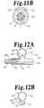
- Figures 10B and 11B depict the addition of the second delivery or venting lumen 22' leading to the second delivery exit or venting port 60' for the applications described above.
- the catheter body 12 is provided with four lumens.
- the configuration and construction of the embodiments of Figures 9 - 11 allows the catheter body 12 and balloon 52 to be integrally formed simply and with a low profile with a plurality of lumens formed in the outer tube 13 and balloon 52.
- the shapes of balloon 52' of Figures 7 and 8 may be employed with the features of this embodiment.
- FIGs 12 through 16 are illustrations of an aneurysm 80 in an artery 90 and the steps of introducing and positioning a deflated balloon catheter, inflating the catheter, delivering the occluding agent, forming the cast and withdrawing the balloon catheter.
- Aneurysm 80 is formed through vessel opening 82 as a thin walled chamber 84 defined by wall 86.
- Figure 17 is a single illustration of the inflation and delivery of the occluding agent into the opening of a branch vessel corresponding to Figure 14B to illustrate that the same steps of Figures 12 - 16 would be employed in that method.
- the introduction of the balloon catheter 10 through the arterial or venous system may be preceded by the introduction of the guide wire 70 in any of the various approaches employed in PTCA or balloon angioplasty.
- the balloon catheter 10, with the balloon 52 deflated may be introduced over the guide wire 70 as depicted in Figure 12A.
- the guide wire 70 may be permanently attached to or positioned in the guide wire lumen 18 extending out the distal tip aperture 36 and/or valve 46, and the assembly may be advanced through the blood vessels until the deflated balloon 52, 52' is positioned and inflated as depicted in Figure 13A.
- the end views of Figures 12B and 13B depict these steps of positioning the guide wire 70 through the main vessel lumen 94 alongside the vessel or aneurysm opening 82 and inflating the balloon 52, 52'.
- a guide catheter and/or introducer shrouding the balloon catheter 10 may also be employed in the introduction procedure, as is well known in the art.
- the progress of introduction is typically observed under fluoroscopy and aided by the earlier identification of the aneurysm or branch vessel by radiopaque media which persists during the introduction and positioning steps.
- Figure 12A is thus a schematic side view illustration of the aneurysm in an artery and the positioning of a deflated balloon catheter distal end segment 16 in relation to the aneurysm opening in accordance with the invention.
- a separate venting catheter 88 may also be positioned alongside the balloon catheter 10 so that the contents of the aneurysm chamber 84 may be aspirated and/or vented out as occluding agent is delivered through the delivery exit port 60, if the balloon catheter 10 is not configured to provide internal aspirating/venting as described above.
- the balloon catheter of the invention in its various embodiments may be employed with a perfusion catheter 96 of any known type placed alongside the balloon 52, or in the U-shaped perfusion channel of the balloon 52', opposite to the opening 82.
- the perfusion catheter 96 allows blood flow past the temporary obstruction of the blood vessel 90 during the procedure without affecting the seal of the balloon to the vessel wall 92 afforded by the inflated balloon.
- the balloon 52, 52' is oriented by twisting the proximal catheter body segment 14 so that the delivery exit port(s) 60, 60' is oriented facing the opening 82.
- the balloon positioning and orientation is observed under fluoroscopy to align the radiopaque markers 15, 17 to the opening 82.
- Testing of the seal may be accomplished by a test inflation while contrast medium is delivered as described above and as shown in Figures 14A and 14B. The test inflation may be avoided if the occluding agent is mixed with contrast media as described above. Alternatively, pressure readings may be taken through the delivery lumen to determine the adequacy of the balloon seal.
- the delivery of the occluding agent or device may be accomplished.
- the occluding agent As the occluding agent is delivered, it either reacts with or displaces the fluid and blood clots in the chamber 84 and makes contact with the chamber wall 86.
- the delivery is depicted in Figures 14A and 14B.
- the fully delivered occluding agent forming an occluding cast is illustrated in Figures 15A and 15B.
- the delivered occluding agent may be solidified through a number of alternative operations to form the occluding cast 100.
- blood flow through the perfusion catheter or channel 53 afforded by the balloon shape may be continued.
- the balloon 52 may be deflated and withdrawn along the guide wire 70.
- the guide wire 70 may then be removed.
- the balloon catheter 10 may be rotated after the delivery step of Figures 14A and 14B to re-orient the delivery exit opening(s) 60, 60' away from the opening 82 and seal the vessel opening 82 with the exterior side wall of the inflated balloon 52.
- the balloon catheter 10 be torsionally rigid enough down the length of the catheter body 12 to transmit rotational torque applied manually at its proximal end segment 14 to its distal end segment 16 in order to rotate the inflated balloon.
- Increased torque transmission ability may also be useful in introducing the catheter 10 and orienting the delivery exit port(s) 60, 60' to the vessel opening 82. It may therefore be desirable to increase the torque by providing a coupling of the distal segment of guide wire 70 with the lumen 18 or exit port 36 to allow torque to be transmitted by the guide wire.
- the guide wire may be fixedly attached permanently in the catheter lumen 18.
- Figure 18 depicts an alternate distal end segment of the balloon catheter of the embodiment of Figure 7 having a permanently installed torque wire 71 attached distally therein by adhesive 72 to the soft tip 34 for increasing the torque transfer for allowing rotation of the balloon.
- the distally attached twist wire 71 is otherwise free in lumen 18 and may be coupled proximally to a knob to allow it to be twisted by the physician in the manner well known in the art and disclosed in U.S. Patent No. 4,582,181. It will be understood that this feature may be implemented in all of the embodiments described above by substitution with the guide wire 70 and associated structure.
- Figure 17 depicts the intermediate step of that process, that is delivering the occluding agent into the branch vessel 102 through the opening 104, corresponding to Figure 14A.
- Figures 12 - 16 may be followed in practicing the invention for the occlusion of branch vessels involving any of the preferred embodiments of the invention.
- aneurysm occluding balloon catheter 10 inner tube 11 catheter body 12 outer tube 13 catheter body proximal end segment 14 first radiopaque marker 15 catheter body distal end segment 16 second radiopaque marker 17 guide wire lumen 18 webs 19 and 21 inflation/deflation lumen 20 delivery lumen 22 additional delivery or venting lumen 22' through hole 23 aperture 24 catheter proximal end connector assembly 26 fitting 28 single lumen tube 30 manifold 32 soft tip 34 distal aperture 36 adaptor fitting 38 valve adaptor 40 tube 42 self sealing, penetrable, distal tip valve 46 valve adaptor 48 tube 50 balloon 52 alternate configuration balloon 52' U-shaped perfusion channel 53 proximal junction 54 distal junction 55 elastic delivery tube extension 56 additional elastic delivery tube extension 56' delivery tube extension lumen 57 inflation/deflation holes 58 delivery exit port 60 additional delivery exit or venting port 60' delivery tube lumen 61 additional delivery tube or venting tube lumen 61' filled distal most extension tube lumen 62 filled distal most delivery lumen 63 filled distal most inflation/def
Landscapes
- Health & Medical Sciences (AREA)
- Life Sciences & Earth Sciences (AREA)
- Surgery (AREA)
- Heart & Thoracic Surgery (AREA)
- Animal Behavior & Ethology (AREA)
- Veterinary Medicine (AREA)
- Engineering & Computer Science (AREA)
- Public Health (AREA)
- Biomedical Technology (AREA)
- General Health & Medical Sciences (AREA)
- Vascular Medicine (AREA)
- Reproductive Health (AREA)
- Nuclear Medicine, Radiotherapy & Molecular Imaging (AREA)
- Medical Informatics (AREA)
- Molecular Biology (AREA)
- Hematology (AREA)
- Anesthesiology (AREA)
- Pulmonology (AREA)
- Biophysics (AREA)
- Child & Adolescent Psychology (AREA)
- Neurosurgery (AREA)
- Surgical Instruments (AREA)
- Media Introduction/Drainage Providing Device (AREA)
Claims (21)
- Cathéter (10) à ballonnet d'obturation allongé destiné à délivrer un agent de bouchage dans une ouverture de vaisseau (104, 82) dans la paroi (92) d'un vaisseau sanguin principal (90) conduisant à un vaisseau périphérique (102) ou un anévrisme (80) pour boucher le lumen du vaisseau périphérique (102) ou la chambre d'anévrisme (84) comprenant :un corps de cathéter allongé (12) ayant un segment d'extrémité proximal (14) et un segment d'extrémité distal (16) adaptés pour être introduits dans le lumen (94) du vaisseau sanguin principal afin de disposer le segment d'extrémité distal s'étendant le long de l'un ou l'autre côté de l'ouverture (104, 82) ;un ballonnet gonflable (52) situé au niveau du segment d'extrémité distal (16) de corps de cathéter ;un lumen (20) de gonflage/dégonflage allongé s'étendant à travers lesdits segments d'extrémité proximal et distal (14, 16) de corps de cathéter en communication fluidique avec l'intérieur dudit ballonnet gonflable (52) à travers lequel du fluide peut être envoyé et retiré pour gonfler et dégonfler le ballonnet gonflable (52) ; etun lumen (22) de distribution d'agent de bouchage s'étendant dans les segments d'extrémité proximal et distal (14, 16) de corps de cathéter et ayant un orifice de sortie de distribution (60) en communication avec ceux-ci situé dans ledit segment d'extrémité distal (16) ; caractérisé en ce que :ledit orifice de sortie de distribution (60) est situé entre les jonctions proximale et distale intermédiaires (54, 55) dudit ballonnet gonflable (52) avec ledit segment d'extrémité distal (16) de corps de cathéter et le long dudit ballonnet gonflable (52) de telle sorte que lors de l'orientation dudit orifice de sortie de distribution (60) en alignement axial avec ladite ouverture (104, 82), le gonflage dudit ballonnet gonflable (52) fait qu'il vient s'appuyer contre la paroi (92) du vaisseau principal et presser ledit orifice de sortie de distribution (60) contre ladite ouverture (104, 82) afin de réaliser un passage de distribution d'agent de bouchage dans ledit orifice de sortie de distribution (60) et ladite ouverture (104, 82) qui supprime sensiblement toute distribution de l'agent de bouchage dans le lumen (94) du vaisseau principal.
- Cathéter (10) à ballonnet d'obturation selon la revendication 1, caractérisé en outre en ce que :ledit ballonnet gonflable (52) est formé d'une paroi de ballonnet s'étendant le long dudit segment d'extrémité distal (16) de corps de cathéter entre lesdites jonctions proximale et distale (54, 55) et s'étendant sur la circonférence dudit segment d'extrémité distal (16) de corps de cathéter, ledit ballonnet gonflable (52) se dilatant vers l'extérieur depuis ledit segment d'extrémité distal (16) de corps de cathéter pour venir s'appuyer contre la paroi de vaisseau (92) lors de son gonflage ; etune partie distale dudit lumen de distribution (22) est formée sur et s'étend le long de ladite paroi de ballonnet à une distance prédéterminée depuis ladite jonction proximale (54) jusqu'audit orifice de sortie de distribution (60) qui se trouve en face de ladite paroi de ballonnet, le gonflage dudit ballonnet gonflable (52) pressant latéralement ledit orifice de sortie de distribution (60) contre l'ouverture (104, 82) dans la paroi de vaisseau (92).
- Cathéter (10) à ballonnet d'obturation selon la revendication 1 ou 2, caractérisé en outre en ce que :ledit corps de cathéter (12) comprend en outre un tube allongé intérieur (11) ayant un lumen intérieur (18) et un tube allongé extérieur (13) entourant ledit tube allongé intérieur (11) et formant ledit lumen de gonflage/dégonflage (20) dans ledit segment d'extrémité proximal (14) de corps de cathéter et dans ledit ballonnet gonflable (52) dans ledit segment d'extrémité distal (16) de corps de cathéter.
- Cathéter (10) à ballonnet d'obturation selon la revendication 1 ou 2, caractérisé en ce que :ledit corps de cathéter (12) comprend en outre un tube allongé intérieur (11) ayant un lumen intérieur (18) et un tube allongé extérieur (13) entourant ledit tube allongé intérieur (11) et formant ledit lumen de gonflage/dégonflage (20) dans ledit segment d'extrémité proximal (16) de corps de cathéter et la paroi de ballonnet dudit ballonnet gonflable (52) dans ledit segment d'extrémité distal (16) de corps de cathéter ; etledit lumen de distribution (22) d'agent de bouchage est formé à l'intérieur dudit tube extérieur (11) et s'étend dans lesdits segments d'extrémité proximal et distal (14, 16) de corps de cathéter, débouchant dans ledit orifice de sortie de distribution (60).
- Cathéter (10) à ballonnet d'obturation selon la revendication 3 ou 4, caractérisé en outre par :une pointe distale (34) dudit segment d'extrémité distal (16) de corps de cathéter ;un fil de guidage (70) pour fournir le guidage du fil afin d'avancer le segment d'extrémité distal (16) de corps de cathéter dans le vaisseau sanguin principal (90) jusqu'à un emplacement de bouchage par rapport à ladite ouverture de vaisseau (104, 82) ;des moyens d'ouverture (24) au niveau de l'extrémité proximale dudit lumen intérieur (18) pour introduire ledit fil de guidage (70) dans ledit lumen intérieur (18), etune ouverture au niveau de ladite pointe distale (34) à travers laquelle ledit fil de guidage (70) peut s'étendre.
- Cathéter (10) à ballonnet d'obturation selon la revendication 1, caractérisé en outre en ce que :ledit ballonnet gonflable (52) est formé d'une paroi de ballonnet s'étendant le long dudit segment d'extrémité distal (16) de corps de cathéter entre lesdites jonctions proximale et distale (54, 55) et s'étendant autour d'au moins une section principale de sa circonférence, ledit ballonnet gonflable (52) se dilate vers l'extérieur depuis ledit segment d'extrémité distal (16) de corps de cathéter pour venir s'appuyer contre la paroi de vaisseau (92) lors du gonflage de celui-ci et déplace une petite section de la circonférence dudit segment d'extrémité distal (16) de corps de cathéter contre la paroi de vaisseau principal (92) ; etune partie distale dudit lumen de distribution (22) s'étend de manière distale dans ledit corps de cathéter allongé depuis ladite jonction proximale (54) jusqu'audit orifice de sortie de distribution (60) qui fait face à ladite paroi de ballonnet, le gonflage dudit ballonnet gonflable (52) presse latéralement ledit orifice de sortie de distribution (60) contre l'ouverture (104, 82) dans la paroi de vaisseau (92).
- Cathéter (10) à ballonnet d'obturation selon la revendication 6, caractérisé en outre en ce que :ledit ballonnet gonflable (52) est formé d'une paroi de ballonnet tubulaire collée audit segment d'extrémité distal (16) de corps de cathéter entre lesdites jonctions proximale et distale (54, 55) dans ladite petite section de sa circonférence pour former une section de ballonnet collée ne pouvant pas se dilater lors du gonflage dudit ballonnet gonflable (52) ; etledit orifice de sortie de distribution (60) est formé dans ladite section de ballonnet collée, le gonflage dudit ballonnet gonflable (52) pressant latéralement ledit orifice de sortie de distribution (60) contre l'ouverture de vaisseau (104, 82).
- Cathéter (10) à ballonnet d'obturation selon l'une quelconque des revendications précédentes 2 à 7, dans lequel ledit ballonnet gonflable (52) est en outre caractérisé par :des moyens destinés à former un canal de perfusion (53) diamétralement opposé audit orifice de sortie de distribution (60) et s'étendant longitudinalement à côté de ladite paroi de ballonnet et de la paroi de vaisseau principal adjacente (92), le canal de perfusion (53) étant scellé depuis l'ouverture de vaisseau (104, 82) lors du gonflage du ballonnet gonflable (52) pour permettre la perfusion de sang dans le canal de perfusion.
- Cathéter (10) à ballonnet d'obturation selon l'une quelconque des revendications précédentes 1 à 8, caractérisé en outre par :des moyens destinés à aspirer le contenu de la chambre d'anévrisme (84) ou du vaisseau périphérique (102) à travers l'ouverture de vaisseau (104, 82) associée à la distribution de l'agent de bouchage à travers le lumen de distribution (22) et l'orifice de sortie de distribution (60).
- Cathéter (10) à ballonnet d'obturation selon l'une quelconque des revendications précédentes 1 à 8, caractérisé en outre par :des moyens destinés à purger le contenu de la chambre d'anévrisme (84) ou du vaisseau périphérique (102) à travers l'ouverture de vaisseau (104, 82) associée à la distribution de l'agent de bouchage à travers le lumen de distribution (22) et l'orifice de sortie de distribution (60).
- Cathéter (10) à ballonnet d'obturation selon l'une quelconque des revendications précédentes 1 à 8, caractérisé en outre par :un autre lumen allongé (22') s'étendant à travers lesdits segments d'extrémité proximal et distal (14, 16) de corps de cathéter et ayant un autre orifice de sortie (60') en communication avec ceux-ci situé dans ledit segment d'extrémité distal (16) adjacent audit orifice de sortie de distribution (60) et le long dudit ballonnet gonflable (52) de telle sorte que lors de l'orientation dudit orifice de sortie de distribution (60) et dudit autre orifice de sortie (60') en alignement axial avec ladite ouverture de vaisseau (104, 82), le gonflage dudit ballonnet gonflable (52) fait qu'il vient s'appuyer contre la paroi de vaisseau principal (92) et presser ledit orifice de sortie (60) et ledit autre orifice de sortie (60') contre ladite ouverture de vaisseau (104, 82).
- Cathéter (10) à ballonnet d'obturation selon l'une quelconque des revendications précédentes 1 à 8, caractérisé en outre par des moyens destinés à purger le contenu de la chambre d'anévrisme (84) ou du vaisseau périphérique (102) à travers l'ouverture de vaisseau (104, 82) associée à la distribution de l'agent de bouchage à travers le lumen de distribution (22) et de l'orifice de sortie de distribution (60), lesdits moyens de purge comprenant en outre :un autre lumen allongé (22') s'étendant à travers lesdits segments d'extrémité proximal et distal (14, 16) de corps de cathéter et ayant un autre orifice de sortie (60') en communication avec ceux-ci situé dans ledit segment d'extrémité distal (16) adjacent audit orifice de sortie de distribution (60) et à côté dudit ballonnet gonflable (52) de telle sorte que lors de l'orientation dudit orifice de sortie de distribution (60) et dudit autre orifice de sortie (60') en alignement axial avec ladite ouverture de vaisseau (104, 82), le gonflage dudit ballonnet gonflable (52) fait qu'il vient s'appuyer contre la paroi de vaisseau principal (92) et presser ledit orifice de sortie de distribution (60) et ledit autre orifice de sortie (60') contre ladite ouverture de vaisseau (104, 82), le contenu de la chambre d'anévrisme (84) ou du vaisseau périphérique (102) pouvant être purgé à travers l'ouverture de vaisseau (104, 82) associée à la distribution de l'agent de bouchage à travers le lumen de distribution (22) et l'orifice de sortie de distribution (60).
- Cathéter (10) à ballonnet d'obturation selon l'une quelconque des revendications précédentes 1 à 8, caractérisé en outre par des moyens pour aspirer le contenu de la chambre d'anévrisme (84) ou du vaisseau périphérique (102) à travers l'ouverture de vaisseau (104, 82) associée à la distribution de l'agent de bouchage par le lumen de distribution (22) et l'orifice de sortie de distribution (60), lesdits moyens d'aspiration comprenant en outre :un autre lumen allongé (22') s'étendant à travers lesdits segments d'extrémité proximal et distal (14, 16) de corps de cathéter et ayant un autre orifice de sortie (60') en communication avec ceux-ci situé dans ledit segment d'extrémité distal (16) adjacent audit orifice de sortie de distribution (60) et à côté dudit ballonnet gonflable (52) de telle sorte que lors de l'orientation dudit orifice de sortie de distribution (60) et dudit autre orifice de sortie (60') en alignement axial avec ladite ouverture de vaisseau (104, 82), le gonflage dudit ballonnet gonflable (52) fait qu'il vient s'appuyer contre la paroi de vaisseau principal (92) et presser ledit orifice de sortie de distribution (60) et ledit autre orifice de sortie (60') contre ladite ouverture de vaisseau (104, 82), le contenu de la chambre d'anévrisme (84) ou du vaisseau périphérique (102) peut être aspiré à travers l'ouverture de vaisseau (104, 82) associée à la distribution de l'agent de bouchage à travers le lumen de distribution (22) et l'orifice de sortie de distribution (60).
- Cathéter (10) à ballonnet d'obturation selon l'une quelconque des revendications précédentes 1 à 13, dans lequel l'agent de bouchage est réactif à la lumière rayonnée pour se solidifier comme une coulée d'obturation solide, et caractérisé en outre par :des moyens destinés à irradier l'agent de bouchage distribué à travers l'ouverture de vaisseau (104, 82) avec de la lumière dirigée dans l'ouverture de vaisseau (104, 82) suffisamment pour réaliser la solidification de l'agent de bouchage distribué.
- Cathéter (10) à ballonnet d'obturation selon l'une quelconque des revendications précédentes 1 à 13, dans lequel l'agent de bouchage est sous forme liquide pour être distribué à travers l'ouverture de vaisseau (104, 82), l'agent de bouchage étant réactif à l'exposition pour former la coulée de bouchage solide.
- Cathéter (10) à ballonnet d'obturation selon l'une quelconque des revendications 1 à 13, dans lequel l'agent de bouchage se trouve sous forme particulaire solide afin d'être distribué par l'ouverture de vaisseau (104, 82), l'agent de bouchage étant efficace pour faire coaguler le sang autour des particules et pour former un thrombus solide à l'intérieur de la chambre d'anévrisme (84) ou du vaisseau périphérique (102) qui fait office de coulée de bouchage solide.
- Cathéter (10) à ballonnet d'obturation selon l'une quelconque des revendications précédentes 1 à 13, dans lequel l'agent de bouchage distribué par l'ouverture de vaisseau (104, 82) est un premier composant d'un agent de bouchage comprenant deux composants, qui réagit avec un second composant pour former une coulée de bouchage, et ledit cathéter à ballonnet d'obturation (10) est caractérisé en outre par :un autre lumen allongé (22') s'étendant dans lesdits segments d'extrémité proximal et distal (14, 16) de corps de cathéter et ayant un autre orifice de sortie (60') en communication avec ceux-ci situé dans ledit segment d'extrémité distal (16) adjacent audit orifice de sortie de distribution (60) et à côté dudit ballonnet gonflable (52) à travers lequel ledit second composant dudit agent de bouchage est distribué de telle sorte que lors de l'orientation dudit orifice de sortie de distribution (60) et dudit autre orifice de sortie (60') en alignement axial avec ladite ouverture de vaisseau (104, 82), le gonflage dudit ballonnet gonflable (52) fait qu'il vient s'appuyer contre la paroi de vaisseau principal (92) et presse ledit orifice de sortie de distribution (60) et ledit autre orifice de sortie (60') contre ladite ouverture de vaisseau (104, 82) pour permettre la distribution des premier et second composants de l'agent de bouchage comprenant deux composants à travers ledit orifice de sortie de distribution (60) et ledit autre orifice de sortie (60'), respectivement, et à travers ladite ouverture de vaisseau (104, 82) dans lequel les premier et second composants de l'agent de bouchage se mélangent dans le vaisseau périphérique (102) ou la chambre d'anévrisme (84) pour y former la coulée de bouchage.
- Cathéter (10) à ballonnet d'obturation selon l'une quelconque des revendications précédentes 14 à 17, caractérisé en outre en ce que :ledit corps de cathéter allongé (12) peut être tourné manuellement depuis ledit segment d'extrémité proximal (14) pour d'abord faire tourner le ballonnet gonflé (52) et aligner ledit ou lesdits orifices de sortie de distribution (60, 60') avec l'ouverture de vaisseau (104, 82) pour effectuer la distribution du ou des agents de bouchage à travers celle-ci et pour ensuite faire tourner le ballonnet gonflé (52) après la distribution de l'agent de bouchage, l'ouverture de vaisseau (104, 82) étant scellée depuis le lumen de vaisseau sanguin (94) lorsque l'agent de bouchage forme la coulée de bouchage.
- Cathéter (10) à ballonnet d'obturation selon l'une quelconque des revendications précédentes 1 à 13, dans lequel l'agent de bouchage est en outre caractérisé par un élément de forme compressible ayant une forme dilatée lorsqu'il n'est pas enfermé et compressible pour être distribué par un espace confiné et par l'ouverture de vaisseau (104, 82), et de manière spécifique une bobine ou des bobines en métaux nobles.
- Cathéter (10) à ballonnet d'obturation selon l'une quelconque des revendications précédentes 1, 2 et 7 à 19, caractérisé en outre par :une pointe distale (34) dudit segment d'extrémité distal (16) de corps de cathéter ;un fil de guidage (70) pour fournir le guidage du fil afin d'avancer le segment d'extrémité distal (16) de corps de cathéter par le vaisseau sanguin principal (90) jusqu'à un emplacement de bouchage par rapport à ladite ouverture de vaisseau (104, 82) ;des moyens d'ouverture (24) au niveau dudit segment d'extrémité proximal dudit corps de cathéter pour introduire ledit fil de guidage (70) dans ledit lumen de gonflage/dégonflage (20) ; etdes moyens de valve (46) pouvant pénétrer formés dans ladite pointe distale (34) et s'étendant dans ledit lumen de gonflage/dégonflage (20) dans lequel peut pénétrer ledit fil de guidage (70) et étant scellés contre ledit fil de guidage (70) s'étendant de manière distale à travers celui-ci pour empêcher toute perte de fluide de gonflage pendant l'introduction du fil et le positionnement dudit cathéter à ballonnet de bouchage (10).
- Cathéter (10) à ballonnet d'obturation selon l'une quelconque des revendications précédentes 1, 2 et 7 à 19, caractérisé en outre par :une pointe distale (34) dudit segment d'extrémité distal (16) de corps de cathéter ; etun fil torsadé (71) pour fournir un guide dudit segment d'extrémité distal (16) de corps de cathéter en position par rapport à une ouverture de vaisseau (104, 82) et pour fournir un transfert de couple depuis ledit segment d'extrémité proximal (14) de corps de cathéter vers ladite pointe distale (34) pour fournir un mouvement de rotation depuis ledit orifice de sortie de distribution (60) en alignement avec l'ouverture de vaisseau (104, 82).
Applications Claiming Priority (2)
| Application Number | Priority Date | Filing Date | Title |
|---|---|---|---|
| US08/148,374 US5795331A (en) | 1994-01-24 | 1994-01-24 | Balloon catheter for occluding aneurysms of branch vessels |
| US148374 | 1994-01-24 |
Publications (3)
| Publication Number | Publication Date |
|---|---|
| EP0664104A2 EP0664104A2 (fr) | 1995-07-26 |
| EP0664104A3 EP0664104A3 (fr) | 1995-09-20 |
| EP0664104B1 true EP0664104B1 (fr) | 1998-09-30 |
Family
ID=22525500
Family Applications (1)
| Application Number | Title | Priority Date | Filing Date |
|---|---|---|---|
| EP95400059A Expired - Lifetime EP0664104B1 (fr) | 1994-01-24 | 1995-01-12 | Cathéter à ballon d'obturation pour anéurismes ou vaisseaux latéraux |
Country Status (5)
| Country | Link |
|---|---|
| US (1) | US5795331A (fr) |
| EP (1) | EP0664104B1 (fr) |
| JP (1) | JPH0833715A (fr) |
| CA (1) | CA2140983A1 (fr) |
| DE (1) | DE69505019T2 (fr) |
Cited By (9)
| Publication number | Priority date | Publication date | Assignee | Title |
|---|---|---|---|---|
| US6951555B1 (en) | 1998-03-16 | 2005-10-04 | Chase Medical, L.P. | Catheter having integral expandable/collapsible lumen |
| US6960228B2 (en) | 2001-06-14 | 2005-11-01 | Cordis Neurovascular, Inc. | Intravascular stent device |
| EP1691879A4 (fr) * | 2003-11-20 | 2006-12-20 | Catheter Exchange Inc | Procede et dispositif d'obliteration d'une cavite |
| US7195648B2 (en) | 2002-05-16 | 2007-03-27 | Cordis Neurovascular, Inc. | Intravascular stent device |
| US7867163B2 (en) | 1998-06-22 | 2011-01-11 | Maquet Cardiovascular Llc | Instrument and method for remotely manipulating a tissue structure |
| US7938842B1 (en) | 1998-08-12 | 2011-05-10 | Maquet Cardiovascular Llc | Tissue dissector apparatus |
| US7972265B1 (en) | 1998-06-22 | 2011-07-05 | Maquet Cardiovascular, Llc | Device and method for remote vessel ligation |
| US7981133B2 (en) | 1995-07-13 | 2011-07-19 | Maquet Cardiovascular, Llc | Tissue dissection method |
| US8241210B2 (en) | 1998-06-22 | 2012-08-14 | Maquet Cardiovascular Llc | Vessel retractor |
Families Citing this family (176)
| Publication number | Priority date | Publication date | Assignee | Title |
|---|---|---|---|---|
| US5556382A (en) * | 1995-08-29 | 1996-09-17 | Scimed Life Systems, Inc. | Balloon perfusion catheter |
| US5980514A (en) * | 1996-07-26 | 1999-11-09 | Target Therapeutics, Inc. | Aneurysm closure device assembly |
| JP3523765B2 (ja) * | 1997-01-24 | 2004-04-26 | テルモ株式会社 | 生体器官拡張器具 |
| NL1005134C2 (nl) * | 1997-01-30 | 1998-08-03 | Industrial Res Bv | Meetkathetersamenstel. |
| GR1002877B (el) * | 1997-02-26 | 1998-03-11 | Αγγειακη ενδοπροθεση με δυνατοτητα ανακλησης (retrievable stent) | |
| AU1918397A (en) * | 1997-03-14 | 1998-10-12 | Harry Bernard Joseph Spoelstra | Arrangement for the endovascular repair of a blood vessel section |
| US6132397A (en) * | 1997-05-01 | 2000-10-17 | Chase Medical Inc. | Integral aortic arch infusion clamp catheter |
| US6068608A (en) * | 1997-05-01 | 2000-05-30 | Chase Medical, Inc. | Method of using integral aortic arch infusion clamp |
| US6635027B1 (en) | 1997-05-19 | 2003-10-21 | Micro Therepeutics, Inc. | Method and apparatus for intramural delivery of a substance |
| US5928260A (en) | 1997-07-10 | 1999-07-27 | Scimed Life Systems, Inc. | Removable occlusion system for aneurysm neck |
| US7569066B2 (en) * | 1997-07-10 | 2009-08-04 | Boston Scientific Scimed, Inc. | Methods and devices for the treatment of aneurysms |
| US6711436B1 (en) | 1997-08-08 | 2004-03-23 | Duke University | Compositions, apparatus and methods for facilitating surgical procedures |
| DE69833665T2 (de) * | 1997-08-08 | 2006-11-09 | Duke University | Zusammensetzungen zur vereinfachung von chirurgischen verfahren |
| US6476069B2 (en) | 1997-09-11 | 2002-11-05 | Provasis Therapeutics Inc. | Compositions for creating embolic agents and uses thereof |
| US6037366A (en) | 1997-09-11 | 2000-03-14 | Prohold Medical Technologies, Inc. | Composition for creating vascular occlusions |
| US6538026B1 (en) * | 1997-09-11 | 2003-03-25 | Provasis Therapeutics, Inc. | Compositions useful for remodeling body spaces |
| US6476070B2 (en) | 1997-09-11 | 2002-11-05 | Provasis Therapeutics Inc. | Compositions useful for remodeling body spaces |
| US6096030A (en) * | 1997-09-23 | 2000-08-01 | Pharmacyclics, Inc. | Light delivery catheter and PDT treatment method |
| US6074407A (en) * | 1997-10-14 | 2000-06-13 | Target Therapeutics, Inc. | Delivery catheter for occlusive implants |
| US6511468B1 (en) * | 1997-10-17 | 2003-01-28 | Micro Therapeutics, Inc. | Device and method for controlling injection of liquid embolic composition |
| US6146373A (en) * | 1997-10-17 | 2000-11-14 | Micro Therapeutics, Inc. | Catheter system and method for injection of a liquid embolic composition and a solidification agent |
| CA2326504A1 (fr) * | 1998-03-30 | 1999-10-07 | David Forest Kallmes | Arret du flux, technique a double ballonnet permettant l'occlusion d'anevrismes ou de vaisseaux sanguins |
| US6463317B1 (en) * | 1998-05-19 | 2002-10-08 | Regents Of The University Of Minnesota | Device and method for the endovascular treatment of aneurysms |
| US6139564A (en) * | 1998-06-16 | 2000-10-31 | Target Therapeutics Inc. | Minimally occlusive flow disruptor stent for bridging aneurysm necks |
| US6165193A (en) * | 1998-07-06 | 2000-12-26 | Microvention, Inc. | Vascular embolization with an expansible implant |
| US6547760B1 (en) * | 1998-08-06 | 2003-04-15 | Cardeon Corporation | Aortic catheter with porous aortic arch balloon and methods for selective aortic perfusion |
| US7790192B2 (en) | 1998-08-14 | 2010-09-07 | Accessclosure, Inc. | Apparatus and methods for sealing a vascular puncture |
| US6254564B1 (en) | 1998-09-10 | 2001-07-03 | Percardia, Inc. | Left ventricular conduit with blood vessel graft |
| AT406336B (de) * | 1998-11-02 | 2000-04-25 | Pro Med Gmbh | Katheter zur intravasculären verbindung zweier gefässabschnitte |
| IT1306191B1 (it) * | 1999-01-04 | 2001-05-30 | Medical Technology S P A | Catetere percutaneo per l'infusione di farmaci in un organismo umano. |
| WO2000059574A1 (fr) * | 1999-04-01 | 2000-10-12 | The University Of Virginia Patent Foundation | Sonde d'administration specifique de site intracavitaire |
| AU6058000A (en) * | 1999-07-12 | 2001-01-30 | Scimed Life Systems, Inc. | Liquid based vaso-occlusive compositions |
| ES2204749T3 (es) * | 2000-02-18 | 2004-05-01 | E.V.R. Endovascular Researches S.A. | Dispositivo endoluminal para el suministro y despliegue de una protesis endoluminal expansionable. |
| US6719778B1 (en) | 2000-03-24 | 2004-04-13 | Endovascular Technologies, Inc. | Methods for treatment of aneurysms |
| US6855154B2 (en) | 2000-08-11 | 2005-02-15 | University Of Louisville Research Foundation, Inc. | Endovascular aneurysm treatment device and method |
| US6558313B1 (en) * | 2000-11-17 | 2003-05-06 | Embro Corporation | Vein harvesting system and method |
| US6527790B2 (en) | 2000-12-07 | 2003-03-04 | Scimed Life Systems, Inc. | Intravascular balloon catheter for embolic coil delivery |
| ES2298357T3 (es) * | 2001-03-14 | 2008-05-16 | E.V.R. Endovascular Researches S.A. | Portador de hilo guia de cateter vascular. |
| US20020165582A1 (en) * | 2001-04-26 | 2002-11-07 | Porter Christopher H. | Method and apparatus for delivering materials to the body |
| US20030045859A1 (en) * | 2001-06-11 | 2003-03-06 | Larry Dominguez | Delivery system using balloon catheter |
| US6454780B1 (en) | 2001-06-21 | 2002-09-24 | Scimed Life Systems, Inc. | Aneurysm neck obstruction device |
| US7687053B2 (en) * | 2001-08-20 | 2010-03-30 | Boston Scientific Scimed, Inc. | Embolic compositions with non-cyanoacrylate rheology modifying agents |
| CA2459234C (fr) * | 2001-09-04 | 2013-03-26 | Micro Therapeutics, Inc. | Catheter d'occlusion dote d'un ballon conforme pour une utilisation dans un systeme vasculaire complexe |
| US6718212B2 (en) | 2001-10-12 | 2004-04-06 | Medtronic, Inc. | Implantable medical electrical lead with light-activated adhesive fixation |
| US7033389B2 (en) * | 2001-10-16 | 2006-04-25 | Scimed Life Systems, Inc. | Tubular prosthesis for external agent delivery |
| US6656152B2 (en) | 2001-11-16 | 2003-12-02 | Ad-Tech Medical Instrument Corp. | Drug delivery catheter assembly with inflatable balloon |
| US20060292206A1 (en) | 2001-11-26 | 2006-12-28 | Kim Steven W | Devices and methods for treatment of vascular aneurysms |
| US7189250B2 (en) * | 2002-01-10 | 2007-03-13 | Scimed Life Systems, Inc. | Aspirating balloon catheter for treating vulnerable plaque |
| US6913597B2 (en) * | 2002-02-26 | 2005-07-05 | Terumo Cardiovascular Systems | Retrograde cannula preventing blood back-flow during stylet removal |
| JP2003265631A (ja) * | 2002-03-14 | 2003-09-24 | Matsushita Electric Ind Co Ltd | 導通管、それを用いたバルーンカテーテル、動脈硬化治療装置、及び、治療システム |
| US7695488B2 (en) | 2002-03-27 | 2010-04-13 | Boston Scientific Scimed, Inc. | Expandable body cavity liner device |
| US7341716B2 (en) * | 2002-04-12 | 2008-03-11 | Boston Scientific Scimed, Inc. | Occlusive composition |
| US7105031B2 (en) * | 2002-04-26 | 2006-09-12 | Medtronic Vascular, Inc. | Balloon-tipped, multi-lumen catheter for endoluminal repair of endoluminal leaks in aortic or aorto-iliac endoluminal grafts |
| US7361368B2 (en) | 2002-06-28 | 2008-04-22 | Advanced Cardiovascular Systems, Inc. | Device and method for combining a treatment agent and a gel |
| US7314484B2 (en) | 2002-07-02 | 2008-01-01 | The Foundry, Inc. | Methods and devices for treating aneurysms |
| US7481821B2 (en) | 2002-11-12 | 2009-01-27 | Thomas J. Fogarty | Embolization device and a method of using the same |
| US7066905B2 (en) * | 2002-11-13 | 2006-06-27 | Squire James C | Method and apparatus for accurate positioning of a dual balloon catheter |
| US20040260382A1 (en) | 2003-02-12 | 2004-12-23 | Fogarty Thomas J. | Intravascular implants and methods of using the same |
| US7651513B2 (en) * | 2003-04-03 | 2010-01-26 | Boston Scientific Scimed, Inc. | Flexible embolic device delivery system |
| US8821473B2 (en) | 2003-04-15 | 2014-09-02 | Abbott Cardiovascular Systems Inc. | Methods and compositions to treat myocardial conditions |
| US8383158B2 (en) | 2003-04-15 | 2013-02-26 | Abbott Cardiovascular Systems Inc. | Methods and compositions to treat myocardial conditions |
| US7241283B2 (en) * | 2003-04-25 | 2007-07-10 | Ad-Tech Medical Instrument Corp. | Method for intracranial catheter treatment of brain tissue |
| US20040236231A1 (en) * | 2003-05-23 | 2004-11-25 | Embro Corporation | Light catheter for illuminating tissue structures |
| US9289195B2 (en) * | 2003-06-04 | 2016-03-22 | Access Closure, Inc. | Auto-retraction apparatus and methods for sealing a vascular puncture |
| US7331979B2 (en) * | 2003-06-04 | 2008-02-19 | Access Closure, Inc. | Apparatus and methods for sealing a vascular puncture |
| US20050015110A1 (en) | 2003-07-18 | 2005-01-20 | Fogarty Thomas J. | Embolization device and a method of using the same |
| US7309345B2 (en) * | 2003-07-25 | 2007-12-18 | Boston Scientific-Scimed, Inc. | Method and system for delivering an implant utilizing a lumen reducing member |
| WO2005023358A1 (fr) * | 2003-09-03 | 2005-03-17 | Acumen Medical, Inc. | Gaine expansible servant a delivrer des instruments et des agents dans une lumiere corporelle |
| DE602004028382D1 (de) * | 2003-10-03 | 2010-09-09 | Medtronic Inc | Erweiterbare führungsschleuse und gerät |
| US20050149117A1 (en) * | 2003-12-24 | 2005-07-07 | Farhad Khosravi | Apparatus and methods for delivering sealing materials during a percutaneous procedure to facilitate hemostasis |
| US20070060950A1 (en) * | 2003-12-24 | 2007-03-15 | Farhad Khosravi | Apparatus and methods for delivering sealing materials during a percutaneous procedure to facilitate hemostasis |
| CA2553940A1 (fr) * | 2004-01-30 | 2005-08-18 | Nmt Medical, Inc. | Dispositifs, systemes et procedes destines a la fermeture d'ouvertures cardiaques |
| US8048086B2 (en) | 2004-02-25 | 2011-11-01 | Femasys Inc. | Methods and devices for conduit occlusion |
| US8048101B2 (en) * | 2004-02-25 | 2011-11-01 | Femasys Inc. | Methods and devices for conduit occlusion |
| US8052669B2 (en) * | 2004-02-25 | 2011-11-08 | Femasys Inc. | Methods and devices for delivery of compositions to conduits |
| US9238127B2 (en) | 2004-02-25 | 2016-01-19 | Femasys Inc. | Methods and devices for delivering to conduit |
| JP4443278B2 (ja) * | 2004-03-26 | 2010-03-31 | テルモ株式会社 | 拡張体付カテーテル |
| US7959634B2 (en) | 2004-03-29 | 2011-06-14 | Soteira Inc. | Orthopedic surgery access devices |
| US7909873B2 (en) | 2006-12-15 | 2011-03-22 | Soteira, Inc. | Delivery apparatus and methods for vertebrostenting |
| US8348971B2 (en) * | 2004-08-27 | 2013-01-08 | Accessclosure, Inc. | Apparatus and methods for facilitating hemostasis within a vascular puncture |
| US7470252B2 (en) * | 2004-09-16 | 2008-12-30 | Boston Scientific Scimed, Inc. | Expandable multi-port therapeutic delivery system |
| US8361490B2 (en) * | 2004-09-16 | 2013-01-29 | Theracoat Ltd. | Biocompatible drug delivery apparatus and methods |
| US7993350B2 (en) | 2004-10-04 | 2011-08-09 | Medtronic, Inc. | Shapeable or steerable guide sheaths and methods for making and using them |
| US7875044B2 (en) | 2004-10-15 | 2011-01-25 | Codman & Shurtleff, Inc. | Remodeling device for aneurysms |
| US20060095121A1 (en) * | 2004-10-28 | 2006-05-04 | Medtronic Vascular, Inc. | Autologous platelet gel on a stent graft |
| US8262693B2 (en) | 2004-11-05 | 2012-09-11 | Accessclosure, Inc. | Apparatus and methods for sealing a vascular puncture |
| US7201918B2 (en) * | 2004-11-16 | 2007-04-10 | Microvention, Inc. | Compositions, systems and methods for treatment of defects in blood vessels |
| US7632242B2 (en) | 2004-12-09 | 2009-12-15 | Boston Scientific Scimed, Inc. | Catheter including a compliant balloon |
| DE102005003632A1 (de) | 2005-01-20 | 2006-08-17 | Fraunhofer-Gesellschaft zur Förderung der angewandten Forschung e.V. | Katheter für die transvaskuläre Implantation von Herzklappenprothesen |
| US7244243B2 (en) * | 2005-03-10 | 2007-07-17 | Banning Gray Lary | Catheter for treatment of severe pulmonary emboli |
| US20060206198A1 (en) * | 2005-03-12 | 2006-09-14 | Churchwell Stacey D | Aneurysm treatment devices and methods |
| US20060206199A1 (en) * | 2005-03-12 | 2006-09-14 | Churchwell Stacey D | Aneurysm treatment devices |
| US9539410B2 (en) | 2005-04-19 | 2017-01-10 | Abbott Cardiovascular Systems Inc. | Methods and compositions for treating post-cardial infarction damage |
| US8828433B2 (en) * | 2005-04-19 | 2014-09-09 | Advanced Cardiovascular Systems, Inc. | Hydrogel bioscaffoldings and biomedical device coatings |
| US20080125745A1 (en) | 2005-04-19 | 2008-05-29 | Shubhayu Basu | Methods and compositions for treating post-cardial infarction damage |
| US8187621B2 (en) | 2005-04-19 | 2012-05-29 | Advanced Cardiovascular Systems, Inc. | Methods and compositions for treating post-myocardial infarction damage |
| US20090259288A1 (en) * | 2005-05-27 | 2009-10-15 | Bandula Wijay | Catheter device for delivery of stents to bifurcated arteries |
| WO2007076324A2 (fr) * | 2005-12-23 | 2007-07-05 | C.R. Bard Inc. | Catheter a ballonnet avec trou de ventilation centralise |
| US20070270933A1 (en) * | 2006-03-09 | 2007-11-22 | Abbott Laboratories | Stent having contoured proximal end |
| US8167929B2 (en) * | 2006-03-09 | 2012-05-01 | Abbott Laboratories | System and method for delivering a stent to a bifurcated vessel |
| US9770230B2 (en) | 2006-06-01 | 2017-09-26 | Maquet Cardiovascular Llc | Endoscopic vessel harvesting system components |
| US7732190B2 (en) | 2006-07-31 | 2010-06-08 | Advanced Cardiovascular Systems, Inc. | Modified two-component gelation systems, methods of use and methods of manufacture |
| US9242005B1 (en) | 2006-08-21 | 2016-01-26 | Abbott Cardiovascular Systems Inc. | Pro-healing agent formulation compositions, methods and treatments |
| US20080167637A1 (en) * | 2006-10-13 | 2008-07-10 | Sonny Yamasaki | Method and apparatus for aneurismal treatment |
| US20100152828A1 (en) * | 2006-11-02 | 2010-06-17 | Pakbaz R Sean | Devices and methods for accessing and treating an aneurysm |
| US8741326B2 (en) | 2006-11-17 | 2014-06-03 | Abbott Cardiovascular Systems Inc. | Modified two-component gelation systems, methods of use and methods of manufacture |
| US9005672B2 (en) | 2006-11-17 | 2015-04-14 | Abbott Cardiovascular Systems Inc. | Methods of modifying myocardial infarction expansion |
| US20100286791A1 (en) * | 2006-11-21 | 2010-11-11 | Goldsmith David S | Integrated system for the ballistic and nonballistic infixion and retrieval of implants |
| US8192760B2 (en) | 2006-12-04 | 2012-06-05 | Abbott Cardiovascular Systems Inc. | Methods and compositions for treating tissue using silk proteins |
| US7896915B2 (en) | 2007-04-13 | 2011-03-01 | Jenavalve Technology, Inc. | Medical device for treating a heart valve insufficiency |
| EP2162101B1 (fr) | 2007-06-25 | 2019-02-20 | MicroVention, Inc. | Prothèse auto-expansible |
| EP2209426A4 (fr) * | 2007-11-02 | 2015-04-22 | Incept Llc | Appareil et procédés de fermeture d'une perforation vasculaire |
| US20090137981A1 (en) * | 2007-11-26 | 2009-05-28 | Valor Medical | Methods of treating a blood vessel |
| US9044318B2 (en) | 2008-02-26 | 2015-06-02 | Jenavalve Technology Gmbh | Stent for the positioning and anchoring of a valvular prosthesis |
| WO2011104269A1 (fr) | 2008-02-26 | 2011-09-01 | Jenavalve Technology Inc. | Stent pour le positionnement et l'ancrage d'une prothèse valvulaire dans un site d'implantation dans le cœur d'un patient |
| US9364206B2 (en) | 2008-04-04 | 2016-06-14 | Access Closure, Inc. | Apparatus and methods for sealing a vascular puncture |
| US8029533B2 (en) | 2008-04-04 | 2011-10-04 | Accessclosure, Inc. | Apparatus and methods for sealing a vascular puncture |
| US20090259210A1 (en) * | 2008-04-10 | 2009-10-15 | Sabbah Hani N | Method, apparatus and kits for forming structural members within the cardiac venous system |
| US10039907B2 (en) * | 2008-04-14 | 2018-08-07 | Innoventions Ltd. | Device, system, and method for releasing substances in a body cavity |
| US10028747B2 (en) | 2008-05-01 | 2018-07-24 | Aneuclose Llc | Coils with a series of proximally-and-distally-connected loops for occluding a cerebral aneurysm |
| US10716573B2 (en) | 2008-05-01 | 2020-07-21 | Aneuclose | Janjua aneurysm net with a resilient neck-bridging portion for occluding a cerebral aneurysm |
| WO2009155319A1 (fr) | 2008-06-17 | 2009-12-23 | Soteira, Inc. | Dispositifs et procédés pour réduction de fracture |
| AU2009282868B2 (en) | 2008-08-19 | 2013-09-05 | Covidien Lp | Detachable tip microcatheter |
| US9554826B2 (en) | 2008-10-03 | 2017-01-31 | Femasys, Inc. | Contrast agent injection system for sonographic imaging |
| US10070888B2 (en) | 2008-10-03 | 2018-09-11 | Femasys, Inc. | Methods and devices for sonographic imaging |
| US12171463B2 (en) | 2008-10-03 | 2024-12-24 | Femasys Inc. | Contrast agent generation and injection system for sonographic imaging |
| WO2010111246A1 (fr) | 2009-03-23 | 2010-09-30 | Soteira, Inc. | Dispositifs et procédés d'implantation d'endoprothèse vertébrale |
| US9463004B2 (en) * | 2009-05-04 | 2016-10-11 | Incept, Llc. | Biomaterials for track and puncture closure |
| JP5612279B2 (ja) * | 2009-06-26 | 2014-10-22 | 日本合成化学工業株式会社 | 心筋梗塞非ヒト動物モデル及びその作製方法 |
| US8357178B2 (en) * | 2009-07-08 | 2013-01-22 | Concentric Medical, Inc. | Vascular and bodily duct treatment devices and methods |
| US8795345B2 (en) * | 2009-07-08 | 2014-08-05 | Concentric Medical, Inc. | Vascular and bodily duct treatment devices and methods |
| US8795317B2 (en) * | 2009-07-08 | 2014-08-05 | Concentric Medical, Inc. | Embolic obstruction retrieval devices and methods |
| US8357179B2 (en) * | 2009-07-08 | 2013-01-22 | Concentric Medical, Inc. | Vascular and bodily duct treatment devices and methods |
| US8529596B2 (en) | 2009-07-08 | 2013-09-10 | Concentric Medical, Inc. | Vascular and bodily duct treatment devices and methods |
| US20110009941A1 (en) * | 2009-07-08 | 2011-01-13 | Concentric Medical, Inc. | Vascular and bodily duct treatment devices and methods |
| US9358140B1 (en) | 2009-11-18 | 2016-06-07 | Aneuclose Llc | Stent with outer member to embolize an aneurysm |
| US9370347B2 (en) | 2010-02-10 | 2016-06-21 | Cardiva Medical, Inc. | Bilateral vessel closure |
| US10821271B2 (en) * | 2010-02-18 | 2020-11-03 | William S. Suhr | Side branch accessible balloon for bifurcation stenting |
| US9402754B2 (en) | 2010-05-18 | 2016-08-02 | Abbott Cardiovascular Systems, Inc. | Expandable endoprostheses, systems, and methods for treating a bifurcated lumen |
| US10856978B2 (en) | 2010-05-20 | 2020-12-08 | Jenavalve Technology, Inc. | Catheter system |
| CA2799459A1 (fr) | 2010-05-25 | 2011-12-01 | Jenavalve Technology Inc. | Valvule prothetique et endoprothese mise en place par catheterisme comprenant une valvule prothetique et un stent |
| US9943668B2 (en) | 2010-07-16 | 2018-04-17 | Sub3 Vascular, Llc | Guidewire and catheter system and method for treating a blood clot |
| US9820728B2 (en) | 2011-01-19 | 2017-11-21 | Access Closure, Inc. | Apparatus and methods for sealing a vascular puncture |
| ES2870965T3 (es) | 2011-01-19 | 2021-10-28 | Access Closure Inc | Procedimientos para sellar una punción vascular |
| KR101680420B1 (ko) | 2011-02-04 | 2016-11-28 | 콘센트릭 메디칼, 인크. | 혈관 및 신체 관 치료 장치 및 방법 |
| US10028745B2 (en) | 2011-03-30 | 2018-07-24 | Noha, Llc | Advanced endovascular clip and method of using same |
| US10398444B2 (en) | 2011-03-30 | 2019-09-03 | Noha, Llc | Advanced endovascular clip and method of using same |
| US9386968B2 (en) | 2011-05-11 | 2016-07-12 | Access Closure, Inc. | Apparatus and methods for sealing a vascular puncture |
| WO2012155093A1 (fr) | 2011-05-11 | 2012-11-15 | Microvention, Inc. | Dispositif permettant d'occlure une lumière |
| DE112012003104T5 (de) * | 2011-07-25 | 2014-04-10 | Terumo K.K. | Behandlungsvorrichtung |
| JP2015500054A (ja) * | 2011-12-02 | 2015-01-05 | シル ヴァスキュラー リミテッド | バルーンカテーテルシステム |
| WO2013136321A1 (fr) * | 2012-03-15 | 2013-09-19 | Flip Technologies Limited | Cathéter à ballonnet et système et procédé pour déterminer la distance d'un site dans un corps humain ou animal à partir d'un emplacement de référence |
| US10124087B2 (en) | 2012-06-19 | 2018-11-13 | Covidien Lp | Detachable coupling for catheter |
| US9358042B2 (en) * | 2013-03-13 | 2016-06-07 | The Spectranetics Corporation | Expandable member for perforation occlusion |
| US11759186B2 (en) * | 2018-06-08 | 2023-09-19 | David S. Goldsmith | Ductus side-entry and prosthetic disorder response systems |
| CN105491978A (zh) | 2013-08-30 | 2016-04-13 | 耶拿阀门科技股份有限公司 | 用于假体瓣膜的径向可折叠框架及其制造方法 |
| CN103480078B (zh) * | 2013-10-12 | 2015-07-08 | 上海凯利泰医疗科技股份有限公司 | 可定向弯曲的球囊导管结构 |
| US9364208B2 (en) | 2014-03-18 | 2016-06-14 | King Abdullah International Medical Research Center | Medical material delivery device |
| EP3270825B1 (fr) | 2015-03-20 | 2020-04-22 | JenaValve Technology, Inc. | Système de pose de prothèse de valvule cardiaque |
| EP3632378B1 (fr) | 2015-05-01 | 2024-05-29 | JenaValve Technology, Inc. | Dispositif à faible débit de stimulateur cardiaque dans le remplacement de valvule cardiaque |
| US10945739B2 (en) | 2015-05-21 | 2021-03-16 | Ecole Polytechnique Federale De Lausanne (Epel) | Device and method for injection, photoactivation and solidifaction of liquid embolic material in the vascular system or other organic cavities |
| US10449336B2 (en) | 2015-08-11 | 2019-10-22 | The Spectranetics Corporation | Temporary occlusions balloon devices and methods for preventing blood flow through a vascular perforation |
| US10499892B2 (en) | 2015-08-11 | 2019-12-10 | The Spectranetics Corporation | Temporary occlusion balloon devices and methods for preventing blood flow through a vascular perforation |
| US11065138B2 (en) | 2016-05-13 | 2021-07-20 | Jenavalve Technology, Inc. | Heart valve prosthesis delivery system and method for delivery of heart valve prosthesis with introducer sheath and loading system |
| CN110392557A (zh) | 2017-01-27 | 2019-10-29 | 耶拿阀门科技股份有限公司 | 心脏瓣膜模拟 |
| FR3080774B1 (fr) | 2018-05-04 | 2022-07-15 | Univ Bordeaux | Catheter, ballon gonflable pour cathether |
| US11185332B2 (en) * | 2018-06-21 | 2021-11-30 | Renalpro Medical, Inc. | Multi-chambered balloon catheter devices and methods |
| US20190388656A1 (en) * | 2018-06-21 | 2019-12-26 | Acclarent, Inc. | Airway dilation balloon with hollow core |
| US11166731B2 (en) | 2019-05-25 | 2021-11-09 | Galaxy Therapeutics Inc. | Systems and methods for treating aneurysms |
| US12102327B2 (en) | 2019-05-25 | 2024-10-01 | Galaxy Therapeutics, Inc. | Systems and methods for treating aneurysms |
| EP4284263A4 (fr) | 2021-01-27 | 2024-06-26 | Galaxy Therapeutics, Inc. | Systèmes et méthodes pour traiter des anévrismes |
| EP4351443A4 (fr) * | 2021-05-18 | 2025-06-04 | Daniel Ezra Walzman | Dispositifs intravasculaires orientables et procédés |
| US12514600B2 (en) | 2022-09-28 | 2026-01-06 | DeepIn Technologies, LLC | Single lumen balloon guide catheter |
| US12171658B2 (en) | 2022-11-09 | 2024-12-24 | Jenavalve Technology, Inc. | Catheter system for sequential deployment of an expandable implant |
| WO2025071553A1 (fr) * | 2023-09-27 | 2025-04-03 | Clearstream Technologies Limited | Dispositifs de pose d'implant |
| CN117179844B (zh) * | 2023-11-08 | 2024-01-26 | 成都纽创医疗器械有限公司 | 一种封堵治疗血管病变和恶性肿瘤的装置 |
Family Cites Families (29)
| Publication number | Priority date | Publication date | Assignee | Title |
|---|---|---|---|---|
| US4323071A (en) * | 1978-04-24 | 1982-04-06 | Advanced Catheter Systems, Inc. | Vascular guiding catheter assembly and vascular dilating catheter assembly and a combination thereof and methods of making the same |
| US4207891A (en) * | 1978-10-10 | 1980-06-17 | Population Research Incorporated | Dispensing instrument with supported balloon |
| US4351342A (en) * | 1981-06-10 | 1982-09-28 | Wiita Bruce E | Balloon catheter |
| US4636195A (en) * | 1982-04-02 | 1987-01-13 | Harvey Wolinsky | Method and apparatus for removing arterial constriction |
| DE3227575A1 (de) * | 1982-07-23 | 1984-02-09 | Karl Heinz Dr. 6300 Gießen Schultheis | Doppelballonkatheter |
| US4693243A (en) * | 1983-01-14 | 1987-09-15 | Buras Sharon Y | Conduit system for directly administering topical anaesthesia to blocked laryngeal-tracheal areas |
| US4582181A (en) * | 1983-08-12 | 1986-04-15 | Advanced Cardiovascular Systems, Inc. | Steerable dilatation catheter |
| US4763653A (en) * | 1985-02-19 | 1988-08-16 | Rockey Arthur G | Medical sleeve |
| US4661094A (en) * | 1985-05-03 | 1987-04-28 | Advanced Cardiovascular Systems | Perfusion catheter and method |
| US4708718A (en) * | 1985-07-02 | 1987-11-24 | Target Therapeutics | Hyperthermic treatment of tumors |
| US4655746A (en) * | 1985-12-02 | 1987-04-07 | Target Therapeutics | Catheter device |
| JPS62236560A (ja) * | 1986-04-09 | 1987-10-16 | テルモ株式会社 | 血管修復用カテ−テル |
| US5041090A (en) * | 1988-01-12 | 1991-08-20 | Scheglov Viktor I | Occluding device |
| DE3821544C2 (de) * | 1988-06-25 | 1994-04-28 | H Prof Dr Med Just | Dilatationskatheter |
| US5087244A (en) * | 1989-01-31 | 1992-02-11 | C. R. Bard, Inc. | Catheter and method for locally applying medication to the wall of a blood vessel or other body lumen |
| US4994033A (en) * | 1989-05-25 | 1991-02-19 | Schneider (Usa) Inc. | Intravascular drug delivery dilatation catheter |
| HU212760B (en) * | 1989-06-20 | 1997-02-28 | Denes | Method and device for the apportion of chemical materials into the vein wall |
| US5242397A (en) * | 1989-06-20 | 1993-09-07 | Cedars-Sinai Medical Center | Catheter device and method of use for intramural delivery of protein kinase C and tyrosine protein kinase inhibitors to prevent restenosis after balloon angioplasty |
| US5049132A (en) * | 1990-01-08 | 1991-09-17 | Cordis Corporation | Balloon catheter for delivering therapeutic agents |
| US5090960A (en) * | 1990-01-12 | 1992-02-25 | Don Michael T Anthony | Regional perfusion dissolution catheter |
| US5222941A (en) * | 1990-01-12 | 1993-06-29 | Don Michael T Anthony | Method of dissolving an obstruction in a vessel |
| US5122136A (en) * | 1990-03-13 | 1992-06-16 | The Regents Of The University Of California | Endovascular electrolytically detachable guidewire tip for the electroformation of thrombus in arteries, veins, aneurysms, vascular malformations and arteriovenous fistulas |
| AR246020A1 (es) * | 1990-10-03 | 1994-03-30 | Hector Daniel Barone Juan Carl | Un dispositivo de balon para implantar una protesis intraluminal aortica para reparar aneurismas. |
| US5318531A (en) * | 1991-06-11 | 1994-06-07 | Cordis Corporation | Infusion balloon catheter |
| US5213576A (en) * | 1991-06-11 | 1993-05-25 | Cordis Corporation | Therapeutic porous balloon catheter |
| US5188595A (en) * | 1991-06-28 | 1993-02-23 | Laserscope | Method for enhanced retention of balloon catheter in body cavity |
| US5234437A (en) * | 1991-12-12 | 1993-08-10 | Target Therapeutics, Inc. | Detachable pusher-vasoocclusion coil assembly with threaded coupling |
| US5368566A (en) * | 1992-04-29 | 1994-11-29 | Cardiovascular Dynamics, Inc. | Delivery and temporary stent catheter having a reinforced perfusion lumen |
| WO1995008289A2 (fr) * | 1993-09-16 | 1995-03-30 | Scimed Life Systems, Inc. | Reparation percutanee d'anomalies cardio-vasculaires et compositions associees |
-
1994
- 1994-01-24 US US08/148,374 patent/US5795331A/en not_active Expired - Lifetime
-
1995
- 1995-01-12 DE DE69505019T patent/DE69505019T2/de not_active Expired - Lifetime
- 1995-01-12 EP EP95400059A patent/EP0664104B1/fr not_active Expired - Lifetime
- 1995-01-24 CA CA002140983A patent/CA2140983A1/fr not_active Abandoned
- 1995-01-24 JP JP7009313A patent/JPH0833715A/ja active Pending
Cited By (9)
| Publication number | Priority date | Publication date | Assignee | Title |
|---|---|---|---|---|
| US7981133B2 (en) | 1995-07-13 | 2011-07-19 | Maquet Cardiovascular, Llc | Tissue dissection method |
| US6951555B1 (en) | 1998-03-16 | 2005-10-04 | Chase Medical, L.P. | Catheter having integral expandable/collapsible lumen |
| US7867163B2 (en) | 1998-06-22 | 2011-01-11 | Maquet Cardiovascular Llc | Instrument and method for remotely manipulating a tissue structure |
| US7972265B1 (en) | 1998-06-22 | 2011-07-05 | Maquet Cardiovascular, Llc | Device and method for remote vessel ligation |
| US8241210B2 (en) | 1998-06-22 | 2012-08-14 | Maquet Cardiovascular Llc | Vessel retractor |
| US7938842B1 (en) | 1998-08-12 | 2011-05-10 | Maquet Cardiovascular Llc | Tissue dissector apparatus |
| US6960228B2 (en) | 2001-06-14 | 2005-11-01 | Cordis Neurovascular, Inc. | Intravascular stent device |
| US7195648B2 (en) | 2002-05-16 | 2007-03-27 | Cordis Neurovascular, Inc. | Intravascular stent device |
| EP1691879A4 (fr) * | 2003-11-20 | 2006-12-20 | Catheter Exchange Inc | Procede et dispositif d'obliteration d'une cavite |
Also Published As
| Publication number | Publication date |
|---|---|
| JPH0833715A (ja) | 1996-02-06 |
| US5795331A (en) | 1998-08-18 |
| CA2140983A1 (fr) | 1995-07-25 |
| EP0664104A3 (fr) | 1995-09-20 |
| DE69505019T2 (de) | 1999-05-06 |
| DE69505019D1 (de) | 1998-11-05 |
| EP0664104A2 (fr) | 1995-07-26 |
Similar Documents
| Publication | Publication Date | Title |
|---|---|---|
| US5795331A (en) | Balloon catheter for occluding aneurysms of branch vessels | |
| EP1316293B1 (fr) | Dispositif pour l'embolisation d'un anevrisme avec element pour occlusion | |
| US6379329B1 (en) | Detachable balloon embolization device and method | |
| US6159197A (en) | Method and apparatus for treating body tissues and bodily fluid vessels | |
| US4705517A (en) | Percutaneously deliverable intravascular occlusion prosthesis | |
| US4819637A (en) | System for artificial vessel embolization and devices for use therewith | |
| JP4353891B2 (ja) | 液体塞栓組成物送出装置 | |
| US6293960B1 (en) | Catheter with shape memory polymer distal tip for deployment of therapeutic devices | |
| EP3641676B1 (fr) | Dispositif d'introduction pour ensemble de tamponnement utérin | |
| CN110996805A (zh) | 粘合封堵系统 | |
| EP1312312A1 (fr) | Dispositif de fermeture pour collet anévrysmal | |
| US20050119684A1 (en) | Aneurysm buttress arrangement | |
| KR102311421B1 (ko) | 볼스텐트 장치 및 사용방법 | |
| US20020165572A1 (en) | Embolic balloon | |
| JP2004511294A (ja) | 血管内インプラントを配置させるための機構 | |
| CN115515510A (zh) | 封堵系统 | |
| KR20170056666A (ko) | 팽창 가능한 바디 디바이스 및 이용 방법 | |
| JP2010172712A (ja) | 血管の創傷をふさぐ装置および方法 | |
| JP2001514568A (ja) | 血管部分の血管内修復のための装置 | |
| WO2022014632A1 (fr) | Ensemble d'instruments médicaux, système d'administration et système médical d'administration d'embole | |
| US6942679B1 (en) | Aneurysm treating instrument | |
| US20020120234A1 (en) | Suction occluder for blood vessels and other body lumens | |
| WO2021199972A1 (fr) | Ensemble de dispositifs médicaux, système de distribution et système médical de distribution d'embole |
Legal Events
| Date | Code | Title | Description |
|---|---|---|---|
| PUAI | Public reference made under article 153(3) epc to a published international application that has entered the european phase |
Free format text: ORIGINAL CODE: 0009012 |
|
| AK | Designated contracting states |
Kind code of ref document: A2 Designated state(s): BE DE FR GB IT NL |
|
| PUAL | Search report despatched |
Free format text: ORIGINAL CODE: 0009013 |
|
| RHK1 | Main classification (correction) |
Ipc: A61M 25/10 |
|
| AK | Designated contracting states |
Kind code of ref document: A3 Designated state(s): BE DE FR GB IT NL |
|
| 17P | Request for examination filed |
Effective date: 19960320 |
|
| 17Q | First examination report despatched |
Effective date: 19970115 |
|
| GRAG | Despatch of communication of intention to grant |
Free format text: ORIGINAL CODE: EPIDOS AGRA |
|
| GRAG | Despatch of communication of intention to grant |
Free format text: ORIGINAL CODE: EPIDOS AGRA |
|
| GRAH | Despatch of communication of intention to grant a patent |
Free format text: ORIGINAL CODE: EPIDOS IGRA |
|
| GRAH | Despatch of communication of intention to grant a patent |
Free format text: ORIGINAL CODE: EPIDOS IGRA |
|
| GRAA | (expected) grant |
Free format text: ORIGINAL CODE: 0009210 |
|
| AK | Designated contracting states |
Kind code of ref document: B1 Designated state(s): BE DE FR GB IT NL |
|
| PG25 | Lapsed in a contracting state [announced via postgrant information from national office to epo] |
Ref country code: NL Free format text: LAPSE BECAUSE OF FAILURE TO SUBMIT A TRANSLATION OF THE DESCRIPTION OR TO PAY THE FEE WITHIN THE PRESCRIBED TIME-LIMIT Effective date: 19980930 Ref country code: BE Free format text: LAPSE BECAUSE OF FAILURE TO SUBMIT A TRANSLATION OF THE DESCRIPTION OR TO PAY THE FEE WITHIN THE PRESCRIBED TIME-LIMIT Effective date: 19980930 |
|
| REF | Corresponds to: |
Ref document number: 69505019 Country of ref document: DE Date of ref document: 19981105 |
|
| ET | Fr: translation filed | ||
| NLV1 | Nl: lapsed or annulled due to failure to fulfill the requirements of art. 29p and 29m of the patents act | ||
| PLBE | No opposition filed within time limit |
Free format text: ORIGINAL CODE: 0009261 |
|
| 26N | No opposition filed | ||
| REG | Reference to a national code |
Ref country code: GB Ref legal event code: IF02 |
|
| PGFP | Annual fee paid to national office [announced via postgrant information from national office to epo] |
Ref country code: DE Payment date: 20140129 Year of fee payment: 20 |
|
| PGFP | Annual fee paid to national office [announced via postgrant information from national office to epo] |
Ref country code: IT Payment date: 20140124 Year of fee payment: 20 Ref country code: FR Payment date: 20140117 Year of fee payment: 20 |
|
| PGFP | Annual fee paid to national office [announced via postgrant information from national office to epo] |
Ref country code: GB Payment date: 20140127 Year of fee payment: 20 |
|
| REG | Reference to a national code |
Ref country code: DE Ref legal event code: R071 Ref document number: 69505019 Country of ref document: DE |
|
| REG | Reference to a national code |
Ref country code: DE Ref legal event code: R071 Ref document number: 69505019 Country of ref document: DE |
|
| REG | Reference to a national code |
Ref country code: GB Ref legal event code: PE20 Expiry date: 20150111 |
|
| PG25 | Lapsed in a contracting state [announced via postgrant information from national office to epo] |
Ref country code: GB Free format text: LAPSE BECAUSE OF EXPIRATION OF PROTECTION Effective date: 20150111 |