EP0664199A1 - Procede d'edition et de definition des vitesses d'injection pour une machine de moulage par injection - Google Patents
Procede d'edition et de definition des vitesses d'injection pour une machine de moulage par injection Download PDFInfo
- Publication number
- EP0664199A1 EP0664199A1 EP94919854A EP94919854A EP0664199A1 EP 0664199 A1 EP0664199 A1 EP 0664199A1 EP 94919854 A EP94919854 A EP 94919854A EP 94919854 A EP94919854 A EP 94919854A EP 0664199 A1 EP0664199 A1 EP 0664199A1
- Authority
- EP
- European Patent Office
- Prior art keywords
- injection
- screw
- injection speed
- speed
- stage
- Prior art date
- Legal status (The legal status is an assumption and is not a legal conclusion. Google has not performed a legal analysis and makes no representation as to the accuracy of the status listed.)
- Granted
Links
Images





Classifications
-
- B—PERFORMING OPERATIONS; TRANSPORTING
- B29—WORKING OF PLASTICS; WORKING OF SUBSTANCES IN A PLASTIC STATE IN GENERAL
- B29C—SHAPING OR JOINING OF PLASTICS; SHAPING OF MATERIAL IN A PLASTIC STATE, NOT OTHERWISE PROVIDED FOR; AFTER-TREATMENT OF THE SHAPED PRODUCTS, e.g. REPAIRING
- B29C45/00—Injection moulding, i.e. forcing the required volume of moulding material through a nozzle into a closed mould; Apparatus therefor
- B29C45/17—Component parts, details or accessories; Auxiliary operations
- B29C45/46—Means for plasticising or homogenising the moulding material or forcing it into the mould
- B29C45/47—Means for plasticising or homogenising the moulding material or forcing it into the mould using screws
- B29C45/50—Axially movable screw
-
- B—PERFORMING OPERATIONS; TRANSPORTING
- B29—WORKING OF PLASTICS; WORKING OF SUBSTANCES IN A PLASTIC STATE IN GENERAL
- B29C—SHAPING OR JOINING OF PLASTICS; SHAPING OF MATERIAL IN A PLASTIC STATE, NOT OTHERWISE PROVIDED FOR; AFTER-TREATMENT OF THE SHAPED PRODUCTS, e.g. REPAIRING
- B29C45/00—Injection moulding, i.e. forcing the required volume of moulding material through a nozzle into a closed mould; Apparatus therefor
- B29C45/17—Component parts, details or accessories; Auxiliary operations
- B29C45/76—Measuring, controlling or regulating
- B29C45/766—Measuring, controlling or regulating the setting or resetting of moulding conditions, e.g. before starting a cycle
-
- B—PERFORMING OPERATIONS; TRANSPORTING
- B29—WORKING OF PLASTICS; WORKING OF SUBSTANCES IN A PLASTIC STATE IN GENERAL
- B29C—SHAPING OR JOINING OF PLASTICS; SHAPING OF MATERIAL IN A PLASTIC STATE, NOT OTHERWISE PROVIDED FOR; AFTER-TREATMENT OF THE SHAPED PRODUCTS, e.g. REPAIRING
- B29C45/00—Injection moulding, i.e. forcing the required volume of moulding material through a nozzle into a closed mould; Apparatus therefor
- B29C45/17—Component parts, details or accessories; Auxiliary operations
- B29C45/76—Measuring, controlling or regulating
- B29C45/77—Measuring, controlling or regulating of velocity or pressure of moulding material
-
- B—PERFORMING OPERATIONS; TRANSPORTING
- B29—WORKING OF PLASTICS; WORKING OF SUBSTANCES IN A PLASTIC STATE IN GENERAL
- B29C—SHAPING OR JOINING OF PLASTICS; SHAPING OF MATERIAL IN A PLASTIC STATE, NOT OTHERWISE PROVIDED FOR; AFTER-TREATMENT OF THE SHAPED PRODUCTS, e.g. REPAIRING
- B29C37/00—Component parts, details, accessories or auxiliary operations, not covered by group B29C33/00 or B29C35/00
- B29C2037/90—Measuring, controlling or regulating
- B29C2037/906—Measuring, controlling or regulating using visualisation means or linked accessories, e.g. screens, printers
Definitions
- the present invention relates to a method for editing and setting an injection speed corresponding to the position of an injection screw in an injection molding machine by means of a display screen and a data input device.
- an injection molding machine which is designed so that an overall screw movement section is divided into a plurality of subsections, an injection speed is set for each screw movement subsection; and injection operation is controlled to equalize the screw moving speed for each screw movement subsection to the injection speed for each subsection.
- the conventional injection molding machine has a problem that the screw moving speed within equally divided section remains constant regardless of the screw position, so that the injection speed changes by stages like a Gauss function, and thus it is hard for the speed to be changed smoothly.
- the object of the present invention is to provide an injection speed editing/setting method for an injection molding machine, capable of easily and securely carrying out setting operation which is required for smooth injection speed changing.
- the first screw position and the second screw position of aforesaid (b), as well as the first injection speed and the second injection speed of aforesaid (c), relating to the first injection stage, and the similar screw positions and injection speeds relating to the second and the following injection stages are set through the ten-keys or the cursor on display screen.
- a screw movement section is divided into a plurality of subsections; an injection speed is determined for each screw movement subsection; each screw movement subsection and corresponding injection speed are set as injection conditions in a control device; the correlation between each set screw movement subsection and corresponding injection speed is graphically displayed on a display screen; and a starting point and an end point are graphically assigned to set a modification section, the individual screw movement subsections are redefined correspondingly to the modification section; and the shape of a segment connecting the starting point and end point is specified and set as a change characteristic of the injection speed in the modification section.
- the correlation between the screw position and injection speed or the correlation between the screw position and injection pressure, obtained by performing injection operation under the set injection conditions, along with the correlation between the set screw movement section and injection speed, is graphically displayed on the display screen, thereby enabling the modification section to be set with reference to the data displayed on the screen, the screw movement section to be redefined and the change characteristic of the injection speed to be reset.
- a subsection (injection stage) from one screw position to another screw position is assigned, and can easily be set by using the display screen so that the injection speed increases or decreases along the oblique straight line or along the circular arc curve.
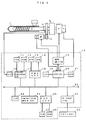
- FIG. 1 is a block diagram showing the principal part of an injection molding machine according to one embodiment to which a method of the present invention is applied.
- Numerals 1 and 2 denote an injection cylinder and a screw, respectively, of the injection molding machine.
- the screw 2 is driven in the direction of an injection axis by a servomotor M1 for injection through drive transducer 5 for converting an axial rotation of a drive source into a linear motion in the direction of the injection axis.
- the screw 2 is rotated for metering by a servomotor M2 for screw rotation through a gear mechanism 3.
- the proximal portion of the screw 2 is provided with a pressure sensor 4, whereby resin pressures which act in the axial direction of the screw 2, that is, injection hold pressure for an injection dwell process and screw back pressure for a metering/kneading process, are detected.
- the injection servomotor M1 is provided with a pulse coder P1 for detecting the position and moving speed of the screw 2, while the screw rotation servomotor M2 is provided with a speed sensor P2 for detecting the rotating speed of the screw 2.
- a control device 10 of the injection molding machine comprises a CNCCPU 25 as a microprocessor for computerized numerical control, a PMCCPU 18 as a microprocessor for programmable machine controller, a servo CPU 20 as a microprocessor for servo control, and a pressure monitoring CPU 17 for sampling the injection hold pressure and screw back pressure through an A/D converter 16, so that information can be transferred between the individual microprocessors by mutually selecting their inputs and outputs through a bus 22.
- the PMCCPU 18 is connected with a ROM 13, which is stored with a sequence program for controlling the sequence operation of the injection molding machine and the like, and a RAM 14 used for temporary storage of computation data and the like.
- the CNCCPU 25 is connected with a ROM 27, which is stored with programs for generally controlling the injection molding machine and the like, and a RAM 28 used for temporary storage of computation data and the like.
- the servo CPU 20 is connected with a ROM 21 loaded with an exclusive control program for servo control and a RAM 19 used for temporary storage of data.
- the pressure monitoring CPU 17 is connected with a ROM 11, which is loaded with a control program for a sampling process for monitoring the injection hold pressure and screw moving speed, and a RAM 12 used for temporary storage of data.
- the servo CPU 20 is connected with a servo amplifier 15 which drives servomotors for various axes for mold clamping, ejector (not shown) operation, injection, screw rotation, etc. in response to commands from the CPU 20.
- a servo amplifier 15 which drives servomotors for various axes for mold clamping, ejector (not shown) operation, injection, screw rotation, etc. in response to commands from the CPU 20.
- Each of outputs from the pulse coders P1 and P2 which are attached to the injection servomotor M1 and the screw rotation servomotor M2, respectively, is fed back to the servo CPU 20.
- a present position storage register and a present speed storage register of the memory 19 are stored respectively with the present position of the screw 2, which is computed by the servo CPU 20 in accordance with feedback pulses from the pulse coder P1, the moving speed and the rotating speed of the screw 2, which is detected by the speed sensor P2.
- the values of the screw position and screw moving speed for an injection stroke are read successively from the aforesaid present position storage register and present speed storage register synchronously with the injection pressure sampling period, and the values of the screw moving speed and injection pressure for each point of time are written in the RAM 12 on the basis of the screw position, and are retained as sampling data for the last injection stroke.
- An interface 23 is an input/output interface which receives signals from limit switches installed in various parts of the injection molding machine and a control panel and deliver various commands to peripheral equipments and the like of the molding machine.
- a manual data input device 29 with display is connected to the bus 22 through a CRT display circuit 26, whereby monitor display screens and function menus can be selected, and various data can be inputted therethrough, and is provided with ten-keys for inputting numerical data and various function keys, etc.
- a nonvolatile memory 24 is a memory for storing molding data such as molding conditions (injection condition, metering/kneading condition, etc.) for injection molding operation and various set values, parameters, macro variables, etc.
- the CNCCPU 25 distributes pulses to the servomotors of the individual axes in accordance with a control program in a ROM 27, while the servo CPU 20 carries out servo control, such as position loop control, speed loop control, current loop control, etc., in the conventional manner, thereby executing the so-called digital servo processing, in accordance with movement commands given to the individual axes by pulse distribution and position and speed feedback signals detected by detectors such as the pulse coder P1 and the speed sensor P2.
- servo control such as position loop control, speed loop control, current loop control, etc.
- FIG. 12(a) is a schematical diagram showing a makeup of an injection condition setting file which is provided in the nonvolatile memory 24 in order to store the correlations between screw movement subsections and injection speeds for the individual screw movement subsections.
- This injection speed setup file stores the injection speed for a screw movement subsections corresponding to injection speed changeover position which represents the screw movement subsections.
- an injection speed changeover position S1 is a metering completion position which is defined when the most advanced screw position is defined as the origin, and an injection speed V1 for a first injection stage defined between the injection speed changeover position S1 and an injection speed changeover position S2 is stored corresponding to the injection speed changeover position S1 which represents the section concerned.
- injection speeds Vi for i'th injection stage is stored corresponding to injection speed change-over positions Si thereafter.
- the injection condition setting file is provided with fields for "identification values" which gives an information on whether the injection speed Vi is set by initialization or by redefinition, and the initial values of identification values Di are all zero.
- An operator first empirically sets a plurality of injection speed changeover positions, thereby dividing the screw movement section into a plurality of subsections to determine the number of injection stages, and inputs the injection speed changeover positions and the injection speeds for the individual injection stages correspondingly to the control device 10, thereby initializing the injection condition setting file in the same manner as in the conventional case, as shown in FIG. 12(a).
- the injection speed control will be effected such that the injection speed varies in stages, in the same manner as in the conventional case.
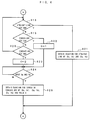
- FIG. 9 is a flowchart showing an outline of an injection speed control processing the CNCCPU 25 carries out in response to an injection start command from the PMCCPU 18.
- the CNCCPU 25 increments the value of the index i (Step T2), and determines whether or not the value of the index i is greater than the set number of injection stage (Step T3).
- the CNCCPU 25 reads the identification value Di, the injection speed Vi and the value of an injection speed changeover position Si+1, which is a start position for the next injection stage, from the injection condition setup file (Step T4), and determines whether or not the identification value Di is 0, that is, whether or not the injection speed i for the i'th injection stage is a constant set by initialization (Step T5).
- the identification value Di is an initial value, that is, 0 so that the CNCCPU 25 outputs to servo CPU 20 the set injection speed Vi for the i'th injection stage read from the injection condition setup file, as a speed command, and starts drive control of the injection servomotor M1 so that the injection speed equals the set injection speed Vi (Step T6).
- the conventional sampling processing by the pressure monitoring CPU 17 is started, and the respective values of the screw moving speed and the injection pressure are loaded into the RAM 12 with reference to the screw position.
- Step T7 the CNCCPU 25 reads present position Sn of the screw 2 from the present position storage register of the memory 19 (Step T7), and determines whether or not the injection speed changeover position Si+1 as the start position for the next injection stage is reached by the screw 2 (Step T8). If this position is not reached, the processings of Steps T7 and T8 are repeatedly executed thereafter so that the decision in Step T8 becomes No (N), and the injection servomotor M1 is operatively controlled as it is so that the injection speed equals the set injection speed Vi for the i'th injection stage.
- Step T8 If the decision in Step T8 is No, that is, if it is confirmed that the injection speed changeover position Si+1 as the start position for the next injection stage is reached by the screw 2, the CNCCPU 25 proceeds to the processing of Step T2, whereupon it increments the value of the index i. Since all the identification values Di are 0, as mentioned before, the CNCCPU 25 repeatedly executes the same processings as the above until the set number of injection stage is exceeded by the value of the index i, and controls the injection speed for the i'th injection stage in accordance with the value of the index i. In this case, the injection speed is changed in quite the same manner as in the conventional case.
- FIGS. 3 to 8 are flowcharts showing an outline of an editing/setting processing to be executed by the PMCCPU 18.
- the relation between the sampling data stored in the RAM 12, e.g., the relationship between actual injection pressure and screw position or the relationship between actual screw moving speed and screw position is also graphically displayed.
- FIG. 2 shows a case in which the correlation (represented by broken line) between the screw movement section and the set injection speed, set in the injection condition setting file, and the relation (represented by full line) between the actual injection pressure and screw position are graphically displayed.
- the PMCCPU 18 reads the values of the injection speed changeover position S1 (metering completion position) and the injection speed V1 from a first address of the injection condition setting file, sets these values as initial values in a position register S and a speed register V (Step 2), and initializes an indication point identification flag F at 0 (Step S3).
- the PMCCPU 18 displays a position assigning cursor in a position (S, V) on a graph which represents the correlation between the screw movement section and the set injection speed (Step S4; see FIG. 2), and enters a standby state in which the operation of a cursor-right key, cursor-left key, cursor-up key, cursor-down key, or decision key F4 is awaited (loop processings of Steps S5 to S9).
- the operator determines a modification section for smooth speed changeover and the change characteristic of the injection speed for this section with reference to the graph which represents the correlation between the screw movement section and the set injection speed and a graph which represents the relation between the actual injection pressure and screw position, determines a starting point position and an end point position of the modification section, and starts starting point assigning operation by means of the cursor-right key, cursor-left key, cursor-up key, and cursor-down key.
- the PMCCPU 18 which repeatedly executes the loop processings of Steps S5 to S9, detects the operation of the cursor-right key, cursor-left key, cursor-up key, or cursor-down key in this discrimination process, and increases or decreases the values in the position register S and the speed register V at predetermined rates a and b in response to the key operation (processes of Steps S10 to S13). Also, the PMCCPU 18 displays the position assigning cursor in the position (S, V), thereby visually indicating position data for the point (S, V), as a candidate for the starting point at the present point of time, for the operator's information (Step S4).
- Step S14 the PMCCPU 18 detects this operation in the discrimination process of Step S9, and determines whether or not its indication point identification flag F maintains its initial value 0 (Step S14). Since the indication point identification flag F is initialized at 0 in the process of Step S3, the decision in Step S14 at this point of time is Yes. Thereupon, the PMCCPU 18 stores a starting point storage register Ss and a starting point speed storage register Vs with the present values in the position register S and the speed register V, respectively (Step S15), and sets 1 for the indication point identification flag F (Step S16).
- Step S5 After setting 1 for the indication point identification flag F, the PMCCPU 18 proceeds to the process of Step S5, whereupon it again enters the standby state in which the operation of any of the various cursor moving keys or the decision key F4 is awaited (loop processes of Steps S5 to S9). Then, the operator operates the various cursor moving keys to move the cursor to a desired end point position in the same manner as aforesaid case (processings of Steps S10 to S13 and Step S4), and operates the decision key F4. After detecting the operation of the decision key F4 in the discrimination process of Step S9, the PMCCPU 18 carries out the discrimination process of Step S14 in the same manner as aforesaid case.
- Step S14 Since 1 is already set for the indication point identification flag F, in this case, the decision in Step S14 is No (N), so that the PMCCPU 18 causes an end point storage register Se and and end point speed storage register Ve to be stored with the present values in the position register S and the speed register V, respectively (Step S17).
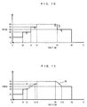
- FIG. 10 shows an example of the starting point position P1(Ss, Vs) of the modification section and an example of the end point position P2(Se, Ve).
- the PMCCPU 18 enters a standby state in which the assignment of the shape of a segment which connects the starting point and the end point of the modification section, that is, the change characteristic of the injection speed, is awaited (loop processes of Steps S18 to S20).
- a straight line or a circular arc may be selected as the shape of the segment which connects the starting point (Ss, Vs) and the end point (Se, Ve) of the modification section.
- the operator When selecting a straight line as the shape of the segment, the operator operates the straight-line key F1, thereby declaring the selection of the straight line upon the control device 10.
- the PMCCPU 18 On detecting the operation of the straight-line key F1 in the discrimination process of Step S18, the PMCCPU 18 obtains an equation for a straight line which connects the starting point (Ss, Vs) and the end point (Se, Ve), and temporarily stores the RAM 14 with this equation (Step S21). This equation is for obtaining the injection speed corresponding to the screw position.
- the operator When selecting an upwardly convex circular arc as the shape of the segment, the operator operates the convex-arc key F2. When selecting a downwardly convex circular arc, the operator operates the concave-arc key F3.
- the PMCCPU 18 detects this in the discrimination process of Step S19, and sets 1 in a convex direction storage register C (Step S22).
- the concave-arc key F3 When the concave-arc key F3 is operated, the PMCCPU 18 detects this in the discrimination process of Step S20, and sets 2 in the convex direction storage register C (Step S23).
- Step S24 the PMCCPU 18 then enters a standby state in which the assignment of a point (Sp, Vp) on circular-arc path is awaited (Step S24).
- the point (Sp, Vp) on circular-arc path is assigned by keyboard entry through the manual data input device 29 with display or in the same manner as those in the cases of aforesaid processes of Steps S4 to S13.
- the PMCCPU 18 detects this in the discrimination process of Step S24, obtains an equation for an upwardly convex 1/2 circular arc or a downwardly convex 1/2 circular arc based on the information for the three points (Ss, Vs), (Sp, Vp) and (Se, Ve) which form the circular arc and the value in the convex direction storage register C, and temporarily stores the RAM 14 with this equation (Step S25).
- This equation is for obtaining the injection speed corresponding to the screw position.
- FIG. 10 shows an example of the starting point position P3(Ss, Vs) of the modification section and an example of the end point position P5(Se, Ve).
- the PMCCPU 18 initializes the value of the address retrieval index i at 0 (Step S26), then increases the value of this index i (Step S27), reads from the injection condition setting file the values of an injection speed changeover position Si as the starting position for the i'th injection stage and injection speed changeover position Si+1 as the start position for the (i + 1)'th injection stage (Step S28), and determines whether or not the screw position Ss corresponding to the starting point position of the modification section is within the range Si ⁇ Ss > Si+1 , that is, whether or not the starting point position (Ss, Vs) of the modification section belongs to the i'th injection stage of the injection condition setting file (Step S29).
- the PMCCPU 18 If the starting point position (Ss, Vs) of the modification section does not belong to the i'th injection stage, the PMCCPU 18 successively increases the value of the index i and repeatedly executes the same processes as are described previously until the i'th injection stage to which the starting point position (Ss, Vs) of the modification section belongs is detected. By doing this, the PMCCPU 18 detects the injection stage to which the starting point position (Ss, Vs) of the modification section belongs, and stores a starting injection stage storage register js with the value of the index i at this point of time (Step S30).
- the PMCCPU 18 further executes the same processes as described previously for the screw position Se corresponding to the end point position of the modification section, thereby detecting the injection stage to which the end point position (Se, Ve) of the modification section belongs (Steps S31 to S33), and stores an end point injection stage storage register je with the value of the index i at this point of time (Step S34).
- the PMCCPU 18 After detecting the injection stage js to which the start point position (Se, Ve) of the modification section belongs and the injection stage je to which the end point position (Se, Ve) belongs in this manner, the PMCCPU 18 separately carries out the processes of Steps S36 to S42, Steps S46 to S51, or Steps S52 to S58, depending on whether or not the difference between js and je is not greater than 1 (Step S35), or greater than 1 and not greater than 2, or greater than 2 (Step S45).
- Step S35 In the case where the difference between js and je is 1, so that the decision in Step S35 is No (N), that is, in the case where the injection stage js to which the starting point position (Ss, Vs) belongs and the injection stage je to which the end point position (Se, Ve) belongs are adjacent to each other, the injection stage of the modification section defined by the starting point position (Ss, Vs) and the end point position (Se, Ve) is newly inserted between the injection stages js and je, so that the number of injection stages of the injection condition setting file needs to be increased by one as a whole.
- the PMCCPU 18 causes data for a je'th address and subsequent addresses of the injection condition setting file to be shifted downward by one address at a time, and provides the storage region of the je'th address of the injection condition setting file with a free region for storing information for the modification section (Step S36).
- the screw position Ss corresponding to the starting point position (Ss, Vs) of the modification section is set as an injection speed changeover position Sje for the newly set je'th injection stage (Step S38)
- the equation for the straight line or 1/2 circular arc obtained in the processings of Step S21 or S25 is set as an injection speed Vje for the section concerned (Step S39)
- the value 1, which indicates that the injection speed is set according to the equation, is set as an identification value Dje for the je'th address (Step S40).
- the screw position Se corresponding to the end point position (Se, Ve) of the modification section is set as an injection speed changeover position Sje+1 for a (je + 1)'th injection stage situated next to the modification section (Step S41).
- an injection speed Ve corresponding to the end point position (Se, Ve) of the modification section is set as an injection speed Vje+1 for the (je + 1)'th injection stage, moreover, the injection speed Ve in the end point position (Se, Ve) for the je'th injection stage newly set as the modification section is made to be equal to the injection speed at the start of the (je + 1)'th injection stage (Step S42).
- FIGS. 12(b) and 11 show a state of a modified injection condition file and a state of a graph based on the modified injection condition file, in the case where the modification section is defined by assigning the starting point position (Ss, Vs) and the end point position (Se, Ve) under the conditions shown in FIGS. 12(a) and 10.
- the result of the modification is not shown in the file of FIG. 12(b), since the modification by defining the section to be modified with a starting point position P3, an end point position P5, and a position P4 of a point on a circular-arc path has not yet actually been started at this point, but the result of such modification is illustrated in FIG. 11. V7 in FIG.
- FIG. 11 indicates a straight line represented by an equation for a third address in FIG. 12(b).
- the modification section is defined by the starting point position P3, end point position P5, and arcuate path point position P4, the starting point position P3 and the end point position P5 are situated in adjacent injection stages, so that the flow of processing is quite the same as described above.
- an injection stage from a screw position S9 to a screw position S10 in FIG. 11 is further inserted as the modification section, and an injection speed changeover position for the final injection stage shifts from a screw position S5 of FIG. 10 to a screw position S10 of FIG. 11.
- V9 in FIG. 11 indicates an upwardly convex circular arc which passes P3, P4 and P5.
- the PMCCPU 18 sets the injection speed Vs in the starting point position (Ss, Vs) of the modification section as the injection speed Vjs for the js'th injection stage to which the starting point position (Ss, Vs) of the modification section belongs, thereby making the injection speed Vs in the starting point position (Ss, Vs) for a (js + 1)'th injection stage newly set as the modification section and the injection speed at the end of the js'th injection stage equal to each other (Step S46).
- the screw position Ss corresponding to the starting point position (Ss, Vs) of the modification section is set as an injection speed changeover position Sjs+1 for the newly set (js + 1)'th injection stage (Step S47); the equation for the straight line or 1/2 circular arc obtained in the process of Step S21 or S25 is set as an injection speed Vjs+1 for the section concerned (Step S48); and the value 1, which indicates that the injection speed is set according to the equation, is set as an identification value Djs+1 for the (js + 1)'th address (Step S49).
- the screw position Se corresponding to the end point position (Se, Ve) of the modification section is set as an injection speed changeover position Sje for the je'th injection stage situated next to the modification section (Step S50).
- the injection speed Ve corresponding to the end point position (Se, Ve) of the modification section is set as the injection speed Vje for the je'th injection stage, moreover, the injection speed Ve in the end point position (Se, Ve) for the (js + 1)'th injection stage newly set as the modification section is made to be equal to the injection speed at the start of the je'th injection stage (Step S51).
- FIG. 12(c) shows a state of a modified injection condition file in the case where the modification section is defined by assigning the starting point position (Ss, Vs) situated in a second injection stage and the end point position (Se, Ve) situated in a fourth injection stage under the conditions shown in FIG. 12(a).
- the injection stages from the injection stage js to the injection stage je can be replaced with three injection stages as a whole without regard to the number of stages.
- the PMCCPU 18 deletes the data corresponding to the addresses js+2 to je-1 in the injection condition file and executes sorting processing for filling the blank so that the storage region of the address js+1 in the injection condition file can be used for setting modification section (Step S52).
- the PMCCPU 18 sets the injection speed Vs in the starting point position (Ss, Vs) of the modification section as the injection speed Vjs for the js'th injection stage to which the starting point position (Ss, Vs) of the modification section belongs, thereby making the injection speed Vs in the starting point position (Ss, Vs) for the (js + 1)'th injection stage newly set as the modification section and the injection speed at the end of the js'th injection stage equal to each other (Step S53).
- the screw position Ss corresponding to the starting point position (Ss, Vs) of the modification section is set as the injection speed changeover position Sjs+1 for the newly set (js + 1)'th injection stage (Step S54); the equation for the straight line or 1/2 circular arc obtained in the process of Step S21 or S25 is set as the injection speed Vjs+1 for the section concerned (Step S55), and the value 1, which indicates that the injection speed is set according to the equation, is set as the identification value Djs+1 for the (js + 1)'th address (Step S56).
- the screw position Se corresponding to the end point position (Se, Ve) of the modification section is set as an injection speed changeover position Sjs+2 for a (js + 2)'th injection stage situated next to the modification section (Step S57).
- the injection speed Ve corresponding to the end point position (Se, Ve) of the modification section is set as an injection speed Vjs+2 for the (js + 2)'th injection stage, moreover, the injection speed Ve at the end point position (Se, Ve) for the (js + 1)'th injection stage newly set as the modification section is made to be equal to the injection speed at the start of the (js + 2)'th injection stage (Step S58).
- FIG. 12(d) shows a state of a modified injection condition file in the case where the modification section is defined by assigning the starting point position (Ss, Vs) situated in the second injection stage and the end point position (Se, Ve) situated in a fifth injection stage under the conditions shown in FIG. 12(a).
- the modification section is defined by assigning the starting point position (Ss, Vs) situated in the second injection stage and the end point position (Se, Ve) situated in a fifth injection stage under the conditions shown in FIG. 12(a).
- third and fourth injection stages of FIG. 12(a) is replaced with a third injection stage of FIG. 12(d).
- the PMCCPU 18 graphically displays the correlation between the screw movement section and the set injection speed on the screen of the manual data input device 29 with display, in accordance with set data of the modified injection condition file, thereby showing the contents of modification to the operator (Step S43; see FIG. 11), and stands by until the operator operates a termination key F5 or a continuation key F6 (Step S44).
- the injection condition file is modified by repeatedly executing the same processes as described previously again in response to the operator's operation, and enters a standby state in which the operation of the termination key F5 or the continuation key F6 is awaited.
- the termination key F5 is operated finally, the PMCCPU 18 finishes the editing/setting process, and proceeds to another process.
- the control of the injection speed based on the set conditions of the modified injection condition storage file is carried out in the following manner in accordance with the injection speed control process shown in FIG. 9.
- the CNCCPU 25 reads the identification value Di, injection speed data Vi, and the value of the injection speed changeover position Si+1 as the start position for the next injection stage from the injection condition setting file (Step T4), and discriminates whether or not the identification value Di is 0, that is, whether the injection speed data Vi for the i'th injection stage is the constant set by initialization or the equation set in the aforementioned editing/setting processing (Step T5).
- the CNCCPU 25 reads the present position Sn of the screw 2 successively from the present position storage register of the memory 19 (Step T9), and determines on each occasion whether or not the injection speed changeover position Si+1 as the start position for the next injection stage is reached by the screw 2 (Step T10).
- Step T9 If the injection speed changeover position Si+1 as the start position for the next injection stage is not reached by the screw 2, the value of the present position Sn read in the process of Step T9 is substituted for the equation set as the injection speed data Vi, and this equation is solved to obtain the value of the injection speed corresponding to the present screw position Sn (Step T11), whereby a speed command corresponding to this can be delivered to the servo CPU 20 to control the drive of the injection servomotor M1 (Step T12).
- the CNCCPU 25 repeatedly executes the processes of Steps T9 to T12, and controls the drive of the injection servomotor M1 so that the injection speed changes according to the equation set as the injection speed data Vi.
- Step T10 If it is detected in the discrimination process of Step T10 that the injection speed changeover position Si+1 is reached by the present screw position Sn, the CNCCPU 25 proceeds again to the process of Step T2, whereupon it increments the value of the index i. Thereafter, until the value of the index i exceeds the set number of injection stages, the CNCCPU 25 repeatedly executes the speed control processes of Steps T6 to T8 or Steps T9 to T12 with every injection stage in accordance with the respective values of the index i and the identification value Di.
- the data of the injection condition setting file can be modified by repeatedly executing the editing/setting process again in the same manner as described previously.
- the injection condition setting file set by initialization may be retained as it is without being modified, and the data of the injection condition setting file may be reproduced on another file before the editing/setting process is started so that data modifying operation based on the editing/setting process can be performed for the reproduced injection condition setup file.
- the data to be used in the injection speed control processings and the editing/setting processings in the second and subsequent cycles are read by specifying either the initially set injection condition setup file or the modified injection condition setup file. This operation is useful in the case where speed setting for the injection control requires restoration of the initial state.
- the change characteristic of the injection speed for the modification section is defined by the straight line or circular arc.
- the change characteristic of the injection speed for the modification section may be defined by using a curved line, such as a parabola or hyperbola.
- the screw position in the modification section is defined only by two points which determine the starting point and end point of the modification section, and all the speeds in the modification section are determined by solving an equation including the present screw position as its variable, so that, even if the change characteristic is a complicated one based on, for example, a parabola or hyperbola, the speed control for the modification section can be effected in the same manner as in the present embodiment as long as the change characteristic can be defined by a functional equation.
- the correlation between the initially set screw movement section and injection speed is graphically displayed on the display screen; a new modification section is set by assigning the starting point and end point on the graph, and the change characteristic of the injection speed for the modification section can optionally be set by assigning the shape of a segment which connects the starting point and end point of the section. Accordingly, the change characteristic of the injection speed can freely be set without setting the injection speed by subdividing the screw movement section, and the necessary injection speed change characteristic can be set with ease even in the case where the injection control requires the injection speed to be changed smoothly.
- the correlation between the screw position and injection speed or the correlation between the screw position and injection pressure obtained by performing injection operation under set injection conditions, can be displayed graphically on the display screen so that the setting operation can be carried out with reference to it, the modification section and the injection speed change characteristic can be accurately set again, in view of deficiencies of the set injection conditions.
- the above-described embodiment represents a case in which the relationship between the screw position and injection speed is modified into the one shown in FIG. 11 by assigning the starting point P1 and the end point P2 of the first modification section and the starting point P3 and the end point P5 of the second modification section on straight lines which represent the previously set relationship between the screw position and injection speed, as shown in FIG. 10.
- the present invention can be applied not only for modifying the previously set relationship, but also for newly establishing the relationship between the screw position and injection speed.
- the injection speed for the first injection stage can be determined by assigning points (S1, V1) and (S2, V1) on the rectangular coordinates of FIG. 11 and by connecting the two points with a straight line. Also in the case of the third injection stage, it is necessary only that the points (Ss, Vs) and (Se, Ve) be assigned and connected with a straight line.
- the injection speed for other injection stages can also be determined in like manner.
Landscapes
- Engineering & Computer Science (AREA)
- Manufacturing & Machinery (AREA)
- Mechanical Engineering (AREA)
- Injection Moulding Of Plastics Or The Like (AREA)
Applications Claiming Priority (4)
| Application Number | Priority Date | Filing Date | Title |
|---|---|---|---|
| JP19269793A JP3162549B2 (ja) | 1993-07-08 | 1993-07-08 | 射出成形機の射出速度編集設定方法 |
| JP19269793 | 1993-07-08 | ||
| JP192697/93 | 1993-07-08 | ||
| PCT/JP1994/001095 WO1995001865A1 (fr) | 1993-07-08 | 1994-07-05 | Procede d'edition et de definition des vitesses d'injection pour une machine de moulage par injection |
Publications (3)
| Publication Number | Publication Date |
|---|---|
| EP0664199A1 true EP0664199A1 (fr) | 1995-07-26 |
| EP0664199A4 EP0664199A4 (fr) | 1997-07-02 |
| EP0664199B1 EP0664199B1 (fr) | 2004-03-31 |
Family
ID=16295549
Family Applications (1)
| Application Number | Title | Priority Date | Filing Date |
|---|---|---|---|
| EP94919854A Expired - Lifetime EP0664199B1 (fr) | 1993-07-08 | 1994-07-05 | Procede d'edition et de definition des vitesses d'injection pour une machine de moulage par injection |
Country Status (6)
| Country | Link |
|---|---|
| US (1) | US6066276A (fr) |
| EP (1) | EP0664199B1 (fr) |
| JP (1) | JP3162549B2 (fr) |
| KR (2) | KR0145194B1 (fr) |
| DE (1) | DE69433658T2 (fr) |
| WO (1) | WO1995001865A1 (fr) |
Cited By (3)
| Publication number | Priority date | Publication date | Assignee | Title |
|---|---|---|---|---|
| EP0961186A3 (fr) * | 1998-05-28 | 2002-11-20 | Fanuc Ltd | Dispositif pour rappeler les conditions de moulage d'une machine de moulage par injection |
| DE19900522B4 (de) * | 1997-07-09 | 2005-07-28 | Niigata Machine Techno Co.Ltd. | Antriebssteuervorrichtung für eine elektrische Spritzgußmaschine |
| CN113459384A (zh) * | 2020-03-31 | 2021-10-01 | 住友重机械工业株式会社 | 注射成型机、注射成型系统 |
Families Citing this family (8)
| Publication number | Priority date | Publication date | Assignee | Title |
|---|---|---|---|---|
| JP2002361702A (ja) * | 2001-06-04 | 2002-12-18 | Fujitsu Ltd | 射出成形機、射出成形機制御装置、射出成形機制御方法および射出成形機制御プログラム |
| JP4210099B2 (ja) * | 2002-10-29 | 2009-01-14 | 東芝機械株式会社 | 射出成形機 |
| US7346425B2 (en) * | 2005-04-27 | 2008-03-18 | Toshiba Kikai Kabushiki Kaisha | Control device for use in injection molding machine |
| JP4594160B2 (ja) * | 2005-04-28 | 2010-12-08 | 東芝機械株式会社 | 射出成形機の制御装置 |
| US20070156279A1 (en) * | 2005-10-19 | 2007-07-05 | Husky Injection Molding Systems Ltd. | Molding machine having human-machine interface |
| JP4091631B2 (ja) * | 2005-11-17 | 2008-05-28 | ファナック株式会社 | 機械の信号処理装置 |
| DE102010024246A1 (de) | 2010-06-18 | 2011-12-22 | Netstal-Maschinen Ag | Verfahren und Vorrichtung zum Betrieb einer angetriebenen Achse bei einer Werkzeugmaschine |
| JP5897682B1 (ja) * | 2014-10-10 | 2016-03-30 | ファナック株式会社 | 固定子の通気路、またはファンを清掃可能な電動機、および電動機の清掃システム |
Family Cites Families (16)
| Publication number | Priority date | Publication date | Assignee | Title |
|---|---|---|---|---|
| DE3306214A1 (de) * | 1982-02-23 | 1983-09-08 | Toshiba Kikai K.K., Tokyo | Vorrichtung zum messen der einspritzgeschwindigkeit einer druckgussmaschine |
| JPS60108155A (ja) * | 1984-04-10 | 1985-06-13 | Ube Ind Ltd | 射出速度制御方法 |
| JPS61220818A (ja) * | 1985-03-28 | 1986-10-01 | Fanuc Ltd | 計量・混練条件をグラフ表示する射出成形機 |
| JPS62218120A (ja) * | 1986-03-20 | 1987-09-25 | Fanuc Ltd | 射出速度の加減速時間が変更できる射出成形機 |
| JPS63130326A (ja) * | 1986-11-20 | 1988-06-02 | Nissei Plastics Ind Co | 射出成形機の成形条件設定装置 |
| JPH0659675B2 (ja) * | 1987-01-30 | 1994-08-10 | 住友重機械工業株式会社 | 射出圧力設定方法及び射出成形機 |
| US5031127A (en) * | 1987-11-27 | 1991-07-09 | Toshiba Machine Co., Ltd. | Molten injection-molding method |
| DE3803832A1 (de) * | 1988-02-09 | 1989-08-17 | Bayer Ag | Substituierte vinylazole |
| EP0364599B1 (fr) * | 1988-03-08 | 1994-05-18 | Fanuc Ltd. | Procede et dispositif de commande de la pression dans une machine de moulage a injection a alimentation electrique |
| JPH07115399B2 (ja) * | 1988-03-28 | 1995-12-13 | ファナック株式会社 | 射出成形機の成形条件記録装置 |
| GB8828713D0 (en) * | 1988-12-08 | 1989-01-11 | Vickers Systems Ltd | Apparatus & method for simultaneous control of two/more related variables |
| JP2608784B2 (ja) * | 1989-07-27 | 1997-05-14 | ファナック株式会社 | 電動式射出成形機 |
| KR970008242B1 (ko) * | 1991-01-14 | 1997-05-22 | 화낙 가부시끼가이샤 | 사출 압력 제어에 있어서의 압력파형설정 방법 및 그 실시 사출 성형기 |
| JP2601736B2 (ja) * | 1991-08-14 | 1997-04-16 | 宇部興産株式会社 | 射出成形機の射出制御方法および装置 |
| US5470218A (en) * | 1993-07-07 | 1995-11-28 | Wheaton Inc. | Graphical interface driven injection blow molding apparatus |
| JP2779759B2 (ja) * | 1993-12-15 | 1998-07-23 | 日精樹脂工業株式会社 | 射出成形機の射出制御方法 |
-
1993
- 1993-07-08 JP JP19269793A patent/JP3162549B2/ja not_active Expired - Fee Related
-
1994
- 1994-07-05 KR KR1019950700885A patent/KR0145194B1/ko not_active Expired - Fee Related
- 1994-07-05 KR KR1019950700885A patent/KR960700877A/ko active Granted
- 1994-07-05 EP EP94919854A patent/EP0664199B1/fr not_active Expired - Lifetime
- 1994-07-05 DE DE69433658T patent/DE69433658T2/de not_active Expired - Fee Related
- 1994-07-05 WO PCT/JP1994/001095 patent/WO1995001865A1/fr not_active Ceased
- 1994-07-05 US US08/392,945 patent/US6066276A/en not_active Expired - Fee Related
Cited By (5)
| Publication number | Priority date | Publication date | Assignee | Title |
|---|---|---|---|---|
| DE19900522B4 (de) * | 1997-07-09 | 2005-07-28 | Niigata Machine Techno Co.Ltd. | Antriebssteuervorrichtung für eine elektrische Spritzgußmaschine |
| EP0961186A3 (fr) * | 1998-05-28 | 2002-11-20 | Fanuc Ltd | Dispositif pour rappeler les conditions de moulage d'une machine de moulage par injection |
| CN113459384A (zh) * | 2020-03-31 | 2021-10-01 | 住友重机械工业株式会社 | 注射成型机、注射成型系统 |
| EP3888874A1 (fr) * | 2020-03-31 | 2021-10-06 | Sumitomo Heavy Industries, Ltd. | Machine de moulage par injection et système de moulage par injection |
| CN113459384B (zh) * | 2020-03-31 | 2023-12-05 | 住友重机械工业株式会社 | 注射成型机、注射成型系统 |
Also Published As
| Publication number | Publication date |
|---|---|
| KR0145194B1 (ko) | 1998-07-15 |
| JP3162549B2 (ja) | 2001-05-08 |
| EP0664199B1 (fr) | 2004-03-31 |
| KR960700877A (ko) | 1996-02-24 |
| DE69433658D1 (de) | 2004-05-06 |
| DE69433658T2 (de) | 2005-02-10 |
| EP0664199A4 (fr) | 1997-07-02 |
| US6066276A (en) | 2000-05-23 |
| JPH0724887A (ja) | 1995-01-27 |
| WO1995001865A1 (fr) | 1995-01-19 |
Similar Documents
| Publication | Publication Date | Title |
|---|---|---|
| EP0664199B1 (fr) | Procede d'edition et de definition des vitesses d'injection pour une machine de moulage par injection | |
| KR0169811B1 (ko) | 제품 품질 영향 요인 해석 방법 및 성형조건 조정 방법 | |
| KR970008245B1 (ko) | 사출압력 모니터 방법 및 장치 | |
| US5817258A (en) | Method of injection control for injection molding machine | |
| US5549857A (en) | Injection pressure monitoring method | |
| EP0566738A1 (fr) | Procede de reglage des conditions d'un moulage par injection | |
| US5292066A (en) | Sealant flow control method in sealing by an industrial robot | |
| US7344664B2 (en) | Pressure waveform setting method for injection pressure control and an injection molding machine | |
| US5611975A (en) | Molding condition setting method for an injection molding machine | |
| JPS61125830A (ja) | 射出成形機の条件設定方式 | |
| US5914077A (en) | Method for setting up a program profile in the control of the injection speed of injection molding machines | |
| EP0264453B1 (fr) | Machine de moulage a injection pouvant modifier la valeur de l'acceleration/deceleration pour reguler la vitesse d'injection | |
| US20020032500A1 (en) | Method for setting an injection speed control pattern of an injection molding machine | |
| US5800748A (en) | Pressure data display method for an injection molding machine | |
| EP0216939B1 (fr) | Machine de moulage a injection presentant un affichage graphique des valeurs de dosage | |
| JP2918210B2 (ja) | 射出成形機の成形情報表示装置 | |
| JP3466772B2 (ja) | 射出成形機の射出圧力制御方法 | |
| JPS6161819A (ja) | 射出速度のプログラム制御装置 | |
| JP3556236B2 (ja) | 射出成形機のモニタ装置 | |
| EP0451298B1 (fr) | Procede permettant de determiner les conditions de moulage dans une machine de moulage par injection | |
| JP3291124B2 (ja) | 射出成形機の射出圧力制御方法及び装置 | |
| JPH09109219A (ja) | 射出成形機における製品良否判別方法 | |
| JP2660630B2 (ja) | 電動式射出成形機の射出制御方式 | |
| JP3195922B2 (ja) | 成形機 | |
| JP3195842B2 (ja) | 成形機の運転条件設定方法および成形機 |
Legal Events
| Date | Code | Title | Description |
|---|---|---|---|
| PUAI | Public reference made under article 153(3) epc to a published international application that has entered the european phase |
Free format text: ORIGINAL CODE: 0009012 |
|
| 17P | Request for examination filed |
Effective date: 19950404 |
|
| AK | Designated contracting states |
Kind code of ref document: A1 Designated state(s): DE GB IT |
|
| A4 | Supplementary search report drawn up and despatched | ||
| AK | Designated contracting states |
Kind code of ref document: A4 Designated state(s): DE GB IT |
|
| 17Q | First examination report despatched |
Effective date: 19991208 |
|
| GRAP | Despatch of communication of intention to grant a patent |
Free format text: ORIGINAL CODE: EPIDOSNIGR1 |
|
| GRAS | Grant fee paid |
Free format text: ORIGINAL CODE: EPIDOSNIGR3 |
|
| GRAA | (expected) grant |
Free format text: ORIGINAL CODE: 0009210 |
|
| RBV | Designated contracting states (corrected) |
Designated state(s): DE |
|
| AK | Designated contracting states |
Kind code of ref document: B1 Designated state(s): DE |
|
| REF | Corresponds to: |
Ref document number: 69433658 Country of ref document: DE Date of ref document: 20040506 Kind code of ref document: P |
|
| RAP2 | Party data changed (patent owner data changed or rights of a patent transferred) |
Owner name: FANUC LTD |
|
| PLBE | No opposition filed within time limit |
Free format text: ORIGINAL CODE: 0009261 |
|
| STAA | Information on the status of an ep patent application or granted ep patent |
Free format text: STATUS: NO OPPOSITION FILED WITHIN TIME LIMIT |
|
| 26N | No opposition filed |
Effective date: 20050104 |
|
| PGFP | Annual fee paid to national office [announced via postgrant information from national office to epo] |
Ref country code: DE Payment date: 20080711 Year of fee payment: 15 |
|
| PG25 | Lapsed in a contracting state [announced via postgrant information from national office to epo] |
Ref country code: DE Free format text: LAPSE BECAUSE OF NON-PAYMENT OF DUE FEES Effective date: 20100202 |