EP0664983A2 - Coulisse de tiroir séquentielle ou similaire - Google Patents
Coulisse de tiroir séquentielle ou similaire Download PDFInfo
- Publication number
- EP0664983A2 EP0664983A2 EP94120257A EP94120257A EP0664983A2 EP 0664983 A2 EP0664983 A2 EP 0664983A2 EP 94120257 A EP94120257 A EP 94120257A EP 94120257 A EP94120257 A EP 94120257A EP 0664983 A2 EP0664983 A2 EP 0664983A2
- Authority
- EP
- European Patent Office
- Prior art keywords
- rail
- pull
- drawer
- roller
- headstock
- Prior art date
- Legal status (The legal status is an assumption and is not a legal conclusion. Google has not performed a legal analysis and makes no representation as to the accuracy of the status listed.)
- Granted
Links
Images
Classifications
-
- A—HUMAN NECESSITIES
- A47—FURNITURE; DOMESTIC ARTICLES OR APPLIANCES; COFFEE MILLS; SPICE MILLS; SUCTION CLEANERS IN GENERAL
- A47B—TABLES; DESKS; OFFICE FURNITURE; CABINETS; DRAWERS; GENERAL DETAILS OF FURNITURE
- A47B88/00—Drawers for tables, cabinets or like furniture; Guides for drawers
- A47B88/40—Sliding drawers; Slides or guides therefor
- A47B88/49—Sliding drawers; Slides or guides therefor with double extensible guides or parts
- A47B88/493—Sliding drawers; Slides or guides therefor with double extensible guides or parts with rollers, ball bearings, wheels, or the like
-
- A—HUMAN NECESSITIES
- A47—FURNITURE; DOMESTIC ARTICLES OR APPLIANCES; COFFEE MILLS; SPICE MILLS; SUCTION CLEANERS IN GENERAL
- A47B—TABLES; DESKS; OFFICE FURNITURE; CABINETS; DRAWERS; GENERAL DETAILS OF FURNITURE
- A47B2210/00—General construction of drawers, guides and guide devices
- A47B2210/0002—Guide construction for drawers
- A47B2210/0008—Guide construction for drawers having a roller on an intermediary slide rail between the cabinet rail and the drawer rail
-
- A—HUMAN NECESSITIES
- A47—FURNITURE; DOMESTIC ARTICLES OR APPLIANCES; COFFEE MILLS; SPICE MILLS; SUCTION CLEANERS IN GENERAL
- A47B—TABLES; DESKS; OFFICE FURNITURE; CABINETS; DRAWERS; GENERAL DETAILS OF FURNITURE
- A47B2210/00—General construction of drawers, guides and guide devices
- A47B2210/0002—Guide construction for drawers
- A47B2210/001—Guide construction for drawers having a roller on the intermediate drawer rail, between the upper and lower rail
-
- A—HUMAN NECESSITIES
- A47—FURNITURE; DOMESTIC ARTICLES OR APPLIANCES; COFFEE MILLS; SPICE MILLS; SUCTION CLEANERS IN GENERAL
- A47B—TABLES; DESKS; OFFICE FURNITURE; CABINETS; DRAWERS; GENERAL DETAILS OF FURNITURE
- A47B2210/00—General construction of drawers, guides and guide devices
- A47B2210/0002—Guide construction for drawers
- A47B2210/0064—Guide sequencing or synchronisation
- A47B2210/007—Three slide synchronisation
-
- A—HUMAN NECESSITIES
- A47—FURNITURE; DOMESTIC ARTICLES OR APPLIANCES; COFFEE MILLS; SPICE MILLS; SUCTION CLEANERS IN GENERAL
- A47B—TABLES; DESKS; OFFICE FURNITURE; CABINETS; DRAWERS; GENERAL DETAILS OF FURNITURE
- A47B2210/00—General construction of drawers, guides and guide devices
- A47B2210/0002—Guide construction for drawers
- A47B2210/0064—Guide sequencing or synchronisation
- A47B2210/0072—Coordinating mechanisms for sequential drawer slides, e.g. by cable
-
- A—HUMAN NECESSITIES
- A47—FURNITURE; DOMESTIC ARTICLES OR APPLIANCES; COFFEE MILLS; SPICE MILLS; SUCTION CLEANERS IN GENERAL
- A47B—TABLES; DESKS; OFFICE FURNITURE; CABINETS; DRAWERS; GENERAL DETAILS OF FURNITURE
- A47B2210/00—General construction of drawers, guides and guide devices
- A47B2210/02—Drawers with hollow lateral walls in two parts
Definitions
- the invention relates to a differential pull-out for drawers or the like.
- a mounting rail to be fastened to a furniture body With a mounting rail to be fastened to a furniture body, a pull-out rail to be fastened to the drawer and a middle rail arranged in between on each side of the drawer, the weight of the drawers between the rails by means of rollers od.
- a deflection roller is arranged at the front and at the rear end of the center rail, and a control cable, which is attached to the mounting rail and on the pull-out rail, is guided over the deflection rollers, with a at the front end of the center rail Headstock is arranged.
- a device is provided to ensure that the rails run differentially with respect to one another.
- This device can consist, for example, of a gearwheel mounted on the central rail, which meshes with toothed racks on the pull-out rail and the mounting rail.
- a simplified version would be the arrangement of a friction wheel on the middle rail.
- a particularly precise guidance of the middle rail is achieved by a control cable which is fastened to the mounting rail and the pull-out rail and which runs on both sides of the middle rail and is guided at the front and rear ends via band guides of the middle rail.
- a control cable which is fastened to the mounting rail and the pull-out rail and which runs on both sides of the middle rail and is guided at the front and rear ends via band guides of the middle rail.
- the object of the invention is to facilitate the hanging of a drawer completely removed from the furniture body in such a differential extension.
- the headstock which is preferably made of plastic, has an arcuate downward facing cap for the front end of the rail, as well as a longitudinal rail web with a straight section and a front section that is bent downwards, wherein an opening is provided in the area of the rail web in which a roller associated with the central rail is mounted.
- the headstock according to the invention facilitates the hanging of the pull-out rail and at the same time offers protection for the deflection roller for the control cable arranged at the front end of the middle rail.
- Hanging the pull-out rail is facilitated in particular by the rail webs arranged in front of and behind the roller.
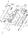
- FIG. 1 shows diagrammatically and pulled apart the parts of the differential pull-out and the drawer frame
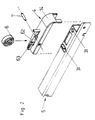
- Fig. 2 shows pulled apart a diagram of the front end of the middle rail and the cover cap
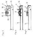
- Fig. 3 shows a side view of the middle rail and the cover cap before assembly
- FIG. 4 shows a section through the central rail and the mounted cover cap
- FIG. 5 shows a side view of the central rail with the cover cap installed.
- the drawer is formed by the two metal drawer frames 28, a front panel, a drawer bottom and the rear wall 27.
- the mounting rail 2 is fastened in a conventional manner to the side wall of the body via a fastening web 40.
- the drawer bottom rests on a horizontal web 41 of the pull-out rail 15.
- In the horizontal web 41 are from the horizontal web 41 expressible tab 42 with pine cone profile or the like in a groove. of the drawer bottom can be pressed in and thus anchor the drawer bottom on the pull-out rail 15.
- the central rail 5 is located between the pull-out rail 15 and the mounting rail 2.
- the central rail 5 has a lower profile 5 ', in which there is a carriage 3 in which rollers are mounted.
- the middle rail 5 is therefore guided in relation to the mounting rail 2 via the rollers mounted in the carriage 3.
- the middle rail 5 is provided with an upper, partially U-shaped profile 5 ′′.
- the catwalks 43, 44 of this profile 5 ' run the rollers 22, 23, which are mounted on the rear adapter 18 of the pull-out rail 15.
- the catwalk 45 of the pull-out rail 15 runs again on the roller 6 mounted on the lower profile 5 'of the center rail 5.
- the central rail 5 has a front and a rear cable pulley 9 for the control cable 10, which is mounted as an endless belt on the cable pulleys 9 on the central rail 5.
- the control cable 10 which is formed, for example, by a wire or plastic cable, has a snap-type cable coupling 8.
- the cable coupling 8 consists of two coupling parts 12, 13 which are connected to the cable ends of the control cable 10.
- the coupling part 13 can be anchored to the mounting rail 2 via a hook.
- a further coupling is provided.
- This consists of an outer coupling part 19 and an inner coupling part 11.
- the outer coupling part 19 is fastened to the pull-out rail 15 by means of screws or rivets 20 which protrude through fastening holes.
- It includes the inner coupling part 11 like pliers.
- the inner coupling part 11 can be pressed into a trough-shaped recess 55 of the outer coupling part 19.
- a roller 6 is supported by means of a rivet 7 on tabs 59 of a headstock 4.
- the runway 45 of the pull-out rail 15 runs on the roller 6.
- two rollers 22, 23 are mounted by means of rents 21.
- the rollers 22 are guided in the upper profile 5 ′′ of the middle rail 5 and are located inside the adapter 18. They are mounted one behind the other.
- the front roller 22 is narrower than the rear roller 23 and is supported on the web 43 of the upper profile 5 ′′ of the center rail 5 when the drawer is moved.
- roller 22 Since the roller 22 is supported on the lower horizontal web 43 and the roller 23 on the upper horizontal web 44, there is no change in the direction of rotation of the rollers 22, 23 during the pulling out or insertion of the drawer, and thus the drawer is guided more smoothly.
- a headstock 4 made of plastic material is attached at the front end of the lower profile 5 'of the central rail 5, as already mentioned.
- the headstock 4 has an opening 62 through which the roller 6 protrudes.
- the headstock 4, which overlaps the front end of the lower profile 5 'of the central rail 5 and at least partially covers it with an arcuate cover cap 14, is provided with a rail web 63 which has a straight section 63' and a front section 63 'which is bent downwards ' having.
- the headstock 4 has pins 30 which can be inserted into the punched holes 31 in the center rail 5 and by means of which the headstock 4 can be fitted onto the center rail 5.
- the headstock 4 is provided with lateral webs 59, into which a rivet 7 can be inserted, which serves as a bearing axis for the roller 6.
- the roller 6 protrudes into a recess 62 in the headstock 14.
- All three adapters 16, 17, 18 have retaining webs 64 projecting downwards.
- the drawer frames 28 are double-walled with an outer wall 65 and an inner wall 66.
- the outer wall 65 has, at its lower edge, a retaining web 67 which is angled inwards and upward, with which it can be suspended in the retaining webs 64 of the adapters 16, 17, 18.
- the inner wall 66 has a horizontal web 68 which rests on the drawer base 38 when the drawer is mounted and a vertical side web 69 which rests on the side of the drawer base 38.
- the transition from the horizontal web 68 to the inner wall 66 is rounded.
- drawer frame 28 is neither welded to the adapters 16, 17, 18 nor to the pull-out rail 15, drawer frames made of any material can be hung in the adapters 16, 17, 18, starting with plastic frames over aluminum frames up to steel frames made of a stainless steel material.
- the furniture manufacturer is therefore given the possibility of equipping drawers with very different prices with the differential pull-out according to the invention.
- a pull-in device 1 for the drawer is mounted on the mounting rail 2. This has a tilting segment 121 acted upon by a spring, which serves as a driver for a pin arranged on the central rail 5.
Landscapes
- Drawers Of Furniture (AREA)
Applications Claiming Priority (2)
| Application Number | Priority Date | Filing Date | Title |
|---|---|---|---|
| AT67/94 | 1994-01-17 | ||
| AT0006794A AT401714B (de) | 1994-01-17 | 1994-01-17 | Differentialauszug für schubladen od. dgl. |
Publications (3)
| Publication Number | Publication Date |
|---|---|
| EP0664983A2 true EP0664983A2 (fr) | 1995-08-02 |
| EP0664983A3 EP0664983A3 (fr) | 1997-02-05 |
| EP0664983B1 EP0664983B1 (fr) | 1999-05-19 |
Family
ID=3480654
Family Applications (1)
| Application Number | Title | Priority Date | Filing Date |
|---|---|---|---|
| EP94120257A Expired - Lifetime EP0664983B1 (fr) | 1994-01-17 | 1994-12-21 | Coulisse de tiroir séquentielle ou similaire |
Country Status (7)
| Country | Link |
|---|---|
| US (1) | US5484199A (fr) |
| EP (1) | EP0664983B1 (fr) |
| JP (1) | JP3013640U (fr) |
| AT (2) | AT401714B (fr) |
| CA (1) | CA2140211C (fr) |
| DE (1) | DE59408284D1 (fr) |
| ES (1) | ES2131624T3 (fr) |
Cited By (5)
| Publication number | Priority date | Publication date | Assignee | Title |
|---|---|---|---|---|
| EP0820712B1 (fr) * | 1996-07-26 | 2001-05-30 | Julius Blum Gesellschaft m.b.H. | Dispositif de guidage de tiroir à glissière double |
| WO2011150434A1 (fr) * | 2010-06-02 | 2011-12-08 | Fulterer Gesellschaft Mbh | Agencement pour dispositif de coulissement de tiroir |
| AT512934B1 (de) * | 2012-11-12 | 2013-12-15 | Blum Gmbh Julius | Schubladenausziehführung |
| AT520691A3 (de) * | 2017-12-04 | 2021-07-15 | Grass Gmbh | Führungssystem |
| US20220295987A1 (en) * | 2021-03-22 | 2022-09-22 | Nan Juen International Co., Ltd. | Telescopic slide rail support pulley structure |
Families Citing this family (12)
| Publication number | Priority date | Publication date | Assignee | Title |
|---|---|---|---|---|
| US7364245B2 (en) * | 2002-12-18 | 2008-04-29 | Pentair Electronic Packaging Company | Lateral alignment device |
| US8403437B2 (en) * | 2004-01-16 | 2013-03-26 | Whirlpool Corporation | Versatile refrigerator crisper system |
| MY144868A (en) * | 2005-02-21 | 2011-11-30 | Harn Marketing Sdn Bhd | "drawer guide rail assembly" |
| US20060226748A1 (en) * | 2005-04-08 | 2006-10-12 | Merillat Industries, Llc | Drawer guide support bracket |
| US20080018213A1 (en) * | 2006-07-20 | 2008-01-24 | Ken-Ching Chen | Drawer slide assembly having an adjustment mechanism |
| DE102007005948A1 (de) * | 2007-02-06 | 2008-08-07 | BSH Bosch und Siemens Hausgeräte GmbH | Kältegerät mit Teleskopauszug |
| US7748801B2 (en) * | 2007-03-14 | 2010-07-06 | Alfit Ag | Telescopic guide for drawers and similar furniture components extendable from a body of furniture |
| AT505562B1 (de) * | 2007-07-24 | 2013-04-15 | Blum Gmbh Julius | Möbelantrieb |
| ES2373499B1 (es) * | 2009-11-25 | 2012-07-23 | Miguel Ángel Rioja Calvo | Dispositivo para guías correderas en chapa metálica estampada para cajones de muebles o similares. |
| DE102016111857B4 (de) * | 2016-06-29 | 2025-01-30 | Paul Hettich Gmbh & Co. Kg | Verfahren zur Montage eines Schubelementes und Bausatz zur verschiebbaren Lagerung eines Schubelementes, Möbel und Haushaltsgerät |
| DE102019124732A1 (de) * | 2019-09-13 | 2021-03-18 | Paul Hettich Gmbh & Co. Kg | Auszugsführung |
| DE102023130080A1 (de) * | 2023-10-31 | 2025-04-30 | Paul Hettich Gmbh & Co. Kg | Auszugsführung und Verfahren zur Montage einer Auszugsführung |
Family Cites Families (9)
| Publication number | Priority date | Publication date | Assignee | Title |
|---|---|---|---|---|
| US2726915A (en) * | 1953-04-22 | 1955-12-13 | Invincible Metal Furniture Co | Lateral thrust bearing for a filing cabinet drawer slide |
| BE561719A (fr) * | 1956-12-03 | |||
| US3722964A (en) * | 1971-07-07 | 1973-03-27 | Oxford Pendaflex Corp | Extensible drawer support |
| US4025138A (en) * | 1975-02-20 | 1977-05-24 | Halle Industries Inc. | Progressive slide assemblies |
| SE429398B (sv) * | 1976-07-14 | 1983-09-05 | Lb Plastics Ltd | Ett sidostycke till en utdragslada och en utdragslada |
| DE2721451A1 (de) * | 1977-05-12 | 1978-11-16 | Bbp Kunststoffwerk | Schubkastenfuehrung fuer moebel |
| DE2904116A1 (de) * | 1979-02-03 | 1980-08-07 | Standard Praezision Gmbh | Teleskopschiene |
| AT381444B (de) * | 1984-07-11 | 1986-10-10 | Fulterer Gmbh | Schubkastenfuehrung fuer ausziehbare moebelteile |
| US4737039A (en) * | 1986-12-08 | 1988-04-12 | Knape & Vogt Manufacturing Company | Drawer rail carrier roller mount |
-
1994
- 1994-01-17 AT AT0006794A patent/AT401714B/de not_active IP Right Cessation
- 1994-12-21 ES ES94120257T patent/ES2131624T3/es not_active Expired - Lifetime
- 1994-12-21 AT AT94120257T patent/ATE180148T1/de not_active IP Right Cessation
- 1994-12-21 EP EP94120257A patent/EP0664983B1/fr not_active Expired - Lifetime
- 1994-12-21 DE DE59408284T patent/DE59408284D1/de not_active Expired - Fee Related
-
1995
- 1995-01-13 CA CA002140211A patent/CA2140211C/fr not_active Expired - Fee Related
- 1995-01-13 JP JP1995000431U patent/JP3013640U/ja not_active Expired - Lifetime
- 1995-01-13 US US08/372,375 patent/US5484199A/en not_active Expired - Fee Related
Cited By (12)
| Publication number | Priority date | Publication date | Assignee | Title |
|---|---|---|---|---|
| EP0820712B1 (fr) * | 1996-07-26 | 2001-05-30 | Julius Blum Gesellschaft m.b.H. | Dispositif de guidage de tiroir à glissière double |
| WO2011150434A1 (fr) * | 2010-06-02 | 2011-12-08 | Fulterer Gesellschaft Mbh | Agencement pour dispositif de coulissement de tiroir |
| AT509925B1 (de) * | 2010-06-02 | 2012-04-15 | Fulterer Gmbh | Anordnung für eine, zumindest zwei teleskopierbar aneinander geführte schienen aufweisende schubladenausziehführung |
| US8845043B2 (en) | 2010-06-02 | 2014-09-30 | Fulterer Gesellschaft Mbh | Arrangement for a drawer pull-out guide |
| AT512934B1 (de) * | 2012-11-12 | 2013-12-15 | Blum Gmbh Julius | Schubladenausziehführung |
| AT512934A4 (de) * | 2012-11-12 | 2013-12-15 | Blum Gmbh Julius | Schubladenausziehführung |
| WO2014071425A1 (fr) | 2012-11-12 | 2014-05-15 | Julius Blum Gmbh | Glissière télescopique de tiroir |
| US9204722B2 (en) | 2012-11-12 | 2015-12-08 | Julius Blum Gmbh | Drawer pull-out guide |
| AT520691A3 (de) * | 2017-12-04 | 2021-07-15 | Grass Gmbh | Führungssystem |
| AT520691B1 (de) * | 2017-12-04 | 2024-04-15 | Grass Gmbh | Führungssystem |
| US20220295987A1 (en) * | 2021-03-22 | 2022-09-22 | Nan Juen International Co., Ltd. | Telescopic slide rail support pulley structure |
| US11825943B2 (en) * | 2021-03-22 | 2023-11-28 | Nan Juen International Co., Ltd. | Telescopic slide rail support pulley structure |
Also Published As
| Publication number | Publication date |
|---|---|
| ES2131624T3 (es) | 1999-08-01 |
| US5484199A (en) | 1996-01-16 |
| JP3013640U (ja) | 1995-07-18 |
| EP0664983A3 (fr) | 1997-02-05 |
| ATA6794A (de) | 1996-04-15 |
| AT401714B (de) | 1996-11-25 |
| EP0664983B1 (fr) | 1999-05-19 |
| ATE180148T1 (de) | 1999-06-15 |
| DE59408284D1 (de) | 1999-06-24 |
| CA2140211A1 (fr) | 1995-07-18 |
| CA2140211C (fr) | 1999-08-31 |
Similar Documents
| Publication | Publication Date | Title |
|---|---|---|
| AT401715B (de) | Differentialauszug für schubladen | |
| AT401714B (de) | Differentialauszug für schubladen od. dgl. | |
| EP0814687B1 (fr) | Monture de guidage pour extraire un tiroir | |
| AT512934B1 (de) | Schubladenausziehführung | |
| DE3942749C2 (de) | Ausziehführungsgarnitur für Schubladen oder dgl. | |
| AT648U1 (de) | Ausziehführung für schubladen | |
| CH638386A5 (de) | Ausziehfuehrung fuer eine schublade. | |
| DE2419546C3 (de) | Schrank mit herausziehbaren Schubladenelementen | |
| EP0806162A1 (fr) | Dispositif de guidage pour tiroirs | |
| EP0761133A1 (fr) | Ensemble de glissières pour tiroirs | |
| DE3127701A1 (de) | "kugel-ausziehfuehrung" | |
| DE9407813U1 (de) | Befestigungsvorrichtung für einstellbare Frontblenden von Schubladen | |
| EP0809956A2 (fr) | Dispositif à tiroirs pour un élément coulissant, encastrable dans une unité d'armoire | |
| DE2601669C3 (de) | Führungseinrichtung für Schubkästen | |
| DE8221386U1 (de) | Ausziehfuehrungsgarnitur fuer schubladen od.dgl. | |
| EP2077084B1 (fr) | Chariot à panneaux et système de suspension de rideaux plats | |
| EP0613639B1 (fr) | Glissières pour tiroirs | |
| DE10000163C1 (de) | Als Vorsatzkasten ausgebildeter Rollladenkasten | |
| DE3010089A1 (de) | Ausziehfuehrung fuer schubladen o.dgl. | |
| EP0699405B1 (fr) | Ensemble de glissières pour tiroirs | |
| DE4115637C2 (fr) | ||
| DE19508378C1 (de) | Gardinengleiter | |
| DE8519535U1 (de) | Schubkastenführung für ausziehbare Möbelteile | |
| AT404221B (de) | Ausziehführungsgarnitur für schubladen | |
| DE9409074U1 (de) | Fachbodenträger |
Legal Events
| Date | Code | Title | Description |
|---|---|---|---|
| PUAI | Public reference made under article 153(3) epc to a published international application that has entered the european phase |
Free format text: ORIGINAL CODE: 0009012 |
|
| AK | Designated contracting states |
Kind code of ref document: A2 Designated state(s): AT CH DE ES FR GB IT LI |
|
| PUAL | Search report despatched |
Free format text: ORIGINAL CODE: 0009013 |
|
| AK | Designated contracting states |
Kind code of ref document: A3 Designated state(s): AT CH DE ES FR GB IT LI |
|
| 17P | Request for examination filed |
Effective date: 19970521 |
|
| 17Q | First examination report despatched |
Effective date: 19980313 |
|
| GRAG | Despatch of communication of intention to grant |
Free format text: ORIGINAL CODE: EPIDOS AGRA |
|
| GRAG | Despatch of communication of intention to grant |
Free format text: ORIGINAL CODE: EPIDOS AGRA |
|
| GRAH | Despatch of communication of intention to grant a patent |
Free format text: ORIGINAL CODE: EPIDOS IGRA |
|
| GRAH | Despatch of communication of intention to grant a patent |
Free format text: ORIGINAL CODE: EPIDOS IGRA |
|
| GRAA | (expected) grant |
Free format text: ORIGINAL CODE: 0009210 |
|
| AK | Designated contracting states |
Kind code of ref document: B1 Designated state(s): AT CH DE ES FR GB IT LI |
|
| REF | Corresponds to: |
Ref document number: 180148 Country of ref document: AT Date of ref document: 19990615 Kind code of ref document: T |
|
| REG | Reference to a national code |
Ref country code: CH Ref legal event code: NV Representative=s name: R. A. EGLI & CO. PATENTANWAELTE Ref country code: CH Ref legal event code: EP |
|
| GBT | Gb: translation of ep patent filed (gb section 77(6)(a)/1977) |
Effective date: 19990519 |
|
| REF | Corresponds to: |
Ref document number: 59408284 Country of ref document: DE Date of ref document: 19990624 |
|
| REG | Reference to a national code |
Ref country code: ES Ref legal event code: FG2A Ref document number: 2131624 Country of ref document: ES Kind code of ref document: T3 |
|
| ET | Fr: translation filed | ||
| PLBE | No opposition filed within time limit |
Free format text: ORIGINAL CODE: 0009261 |
|
| STAA | Information on the status of an ep patent application or granted ep patent |
Free format text: STATUS: NO OPPOSITION FILED WITHIN TIME LIMIT |
|
| 26N | No opposition filed | ||
| PGFP | Annual fee paid to national office [announced via postgrant information from national office to epo] |
Ref country code: CH Payment date: 20011217 Year of fee payment: 8 |
|
| PGFP | Annual fee paid to national office [announced via postgrant information from national office to epo] |
Ref country code: FR Payment date: 20011218 Year of fee payment: 8 |
|
| PGFP | Annual fee paid to national office [announced via postgrant information from national office to epo] |
Ref country code: GB Payment date: 20011219 Year of fee payment: 8 |
|
| REG | Reference to a national code |
Ref country code: GB Ref legal event code: IF02 |
|
| PGFP | Annual fee paid to national office [announced via postgrant information from national office to epo] |
Ref country code: ES Payment date: 20021212 Year of fee payment: 9 |
|
| PGFP | Annual fee paid to national office [announced via postgrant information from national office to epo] |
Ref country code: AT Payment date: 20021213 Year of fee payment: 9 |
|
| PG25 | Lapsed in a contracting state [announced via postgrant information from national office to epo] |
Ref country code: GB Free format text: LAPSE BECAUSE OF NON-PAYMENT OF DUE FEES Effective date: 20021221 |
|
| PG25 | Lapsed in a contracting state [announced via postgrant information from national office to epo] |
Ref country code: LI Free format text: LAPSE BECAUSE OF NON-PAYMENT OF DUE FEES Effective date: 20021231 Ref country code: CH Free format text: LAPSE BECAUSE OF NON-PAYMENT OF DUE FEES Effective date: 20021231 |
|
| PGFP | Annual fee paid to national office [announced via postgrant information from national office to epo] |
Ref country code: DE Payment date: 20030226 Year of fee payment: 9 |
|
| GBPC | Gb: european patent ceased through non-payment of renewal fee |
Effective date: 20021221 |
|
| REG | Reference to a national code |
Ref country code: CH Ref legal event code: PL |
|
| PG25 | Lapsed in a contracting state [announced via postgrant information from national office to epo] |
Ref country code: FR Free format text: LAPSE BECAUSE OF NON-PAYMENT OF DUE FEES Effective date: 20030901 |
|
| REG | Reference to a national code |
Ref country code: FR Ref legal event code: ST |
|
| PG25 | Lapsed in a contracting state [announced via postgrant information from national office to epo] |
Ref country code: AT Free format text: LAPSE BECAUSE OF NON-PAYMENT OF DUE FEES Effective date: 20031221 |
|
| PG25 | Lapsed in a contracting state [announced via postgrant information from national office to epo] |
Ref country code: ES Free format text: LAPSE BECAUSE OF NON-PAYMENT OF DUE FEES Effective date: 20031222 |
|
| PG25 | Lapsed in a contracting state [announced via postgrant information from national office to epo] |
Ref country code: DE Free format text: LAPSE BECAUSE OF NON-PAYMENT OF DUE FEES Effective date: 20040701 |
|
| REG | Reference to a national code |
Ref country code: ES Ref legal event code: FD2A Effective date: 20031222 |
|
| PG25 | Lapsed in a contracting state [announced via postgrant information from national office to epo] |
Ref country code: IT Free format text: LAPSE BECAUSE OF NON-PAYMENT OF DUE FEES;WARNING: LAPSES OF ITALIAN PATENTS WITH EFFECTIVE DATE BEFORE 2007 MAY HAVE OCCURRED AT ANY TIME BEFORE 2007. THE CORRECT EFFECTIVE DATE MAY BE DIFFERENT FROM THE ONE RECORDED. Effective date: 20051221 |